EP1123783A2 - Ensemble pivotant pour positionner des outils sur des structures support - Google Patents
Ensemble pivotant pour positionner des outils sur des structures support Download PDFInfo
- Publication number
- EP1123783A2 EP1123783A2 EP00106300A EP00106300A EP1123783A2 EP 1123783 A2 EP1123783 A2 EP 1123783A2 EP 00106300 A EP00106300 A EP 00106300A EP 00106300 A EP00106300 A EP 00106300A EP 1123783 A2 EP1123783 A2 EP 1123783A2
- Authority
- EP
- European Patent Office
- Prior art keywords
- sleeve
- pivot bearing
- profile
- bearing according
- notches
- Prior art date
- Legal status (The legal status is an assumption and is not a legal conclusion. Google has not performed a legal analysis and makes no representation as to the accuracy of the status listed.)
- Withdrawn
Links
- 238000006073 displacement reaction Methods 0.000 claims 1
- 238000011161 development Methods 0.000 description 3
- 230000018109 developmental process Effects 0.000 description 3
- 244000089486 Phragmites australis subsp australis Species 0.000 description 1
- 230000002411 adverse Effects 0.000 description 1
- 230000001419 dependent effect Effects 0.000 description 1
- 238000001514 detection method Methods 0.000 description 1
- 230000000694 effects Effects 0.000 description 1
- 230000002093 peripheral effect Effects 0.000 description 1
Images

Classifications
-
- F—MECHANICAL ENGINEERING; LIGHTING; HEATING; WEAPONS; BLASTING
- F16—ENGINEERING ELEMENTS AND UNITS; GENERAL MEASURES FOR PRODUCING AND MAINTAINING EFFECTIVE FUNCTIONING OF MACHINES OR INSTALLATIONS; THERMAL INSULATION IN GENERAL
- F16B—DEVICES FOR FASTENING OR SECURING CONSTRUCTIONAL ELEMENTS OR MACHINE PARTS TOGETHER, e.g. NAILS, BOLTS, CIRCLIPS, CLAMPS, CLIPS OR WEDGES; JOINTS OR JOINTING
- F16B7/00—Connections of rods or tubes, e.g. of non-circular section, mutually, including resilient connections
- F16B7/04—Clamping or clipping connections
- F16B7/0406—Clamping or clipping connections for rods or tubes being coaxial
- F16B7/0413—Clamping or clipping connections for rods or tubes being coaxial for tubes using the innerside thereof
-
- B—PERFORMING OPERATIONS; TRANSPORTING
- B25—HAND TOOLS; PORTABLE POWER-DRIVEN TOOLS; MANIPULATORS
- B25J—MANIPULATORS; CHAMBERS PROVIDED WITH MANIPULATION DEVICES
- B25J15/00—Gripping heads and other end effectors
- B25J15/0052—Gripping heads and other end effectors multiple gripper units or multiple end effectors
- B25J15/0061—Gripping heads and other end effectors multiple gripper units or multiple end effectors mounted on a modular gripping structure
-
- F—MECHANICAL ENGINEERING; LIGHTING; HEATING; WEAPONS; BLASTING
- F16—ENGINEERING ELEMENTS AND UNITS; GENERAL MEASURES FOR PRODUCING AND MAINTAINING EFFECTIVE FUNCTIONING OF MACHINES OR INSTALLATIONS; THERMAL INSULATION IN GENERAL
- F16B—DEVICES FOR FASTENING OR SECURING CONSTRUCTIONAL ELEMENTS OR MACHINE PARTS TOGETHER, e.g. NAILS, BOLTS, CIRCLIPS, CLAMPS, CLIPS OR WEDGES; JOINTS OR JOINTING
- F16B21/00—Means for preventing relative axial movement of a pin, spigot, shaft or the like and a member surrounding it; Stud-and-socket releasable fastenings
- F16B21/02—Releasable fastening devices locking by rotation
-
- Y—GENERAL TAGGING OF NEW TECHNOLOGICAL DEVELOPMENTS; GENERAL TAGGING OF CROSS-SECTIONAL TECHNOLOGIES SPANNING OVER SEVERAL SECTIONS OF THE IPC; TECHNICAL SUBJECTS COVERED BY FORMER USPC CROSS-REFERENCE ART COLLECTIONS [XRACs] AND DIGESTS
- Y10—TECHNICAL SUBJECTS COVERED BY FORMER USPC
- Y10T—TECHNICAL SUBJECTS COVERED BY FORMER US CLASSIFICATION
- Y10T403/00—Joints and connections
- Y10T403/70—Interfitted members
- Y10T403/7026—Longitudinally splined or fluted rod
- Y10T403/7035—Specific angle or shape of rib, key, groove, or shoulder
Definitions
- the present invention relates to a rotary bearing formed from profile bars, particularly attached to robot arms and from these movable supports for attachment of tools, such as clamping, suction, gripping devices and / or other work tools.
- Such profile bars are used for the assembly of support frames, which in turn are intended in particular for attachment to robot arms and for the connection of tools, such as clamping, suction, gripping devices and / or other working aids.
- the profile bars provided for this purpose which are connected to one another by appropriately profile-adapted clamping pieces, are generally octagon profiles, which in turn are generally provided with at least two radially opposing grooves.
- Octagonal profile bars are therefore preferably used for the stated purpose in order to be able to attach the profile-matched clamping pieces in eight different radial orientations to the profile bars, depending on the orientation with which the above-mentioned tools are seated on the support frame or the crossing direction held by the same clamping piece Should have profile bars.
- the object of the present invention is therefore a To create swivel bearings on such profile bars, the simple Wisely and with simple means in relation to the longitudinal axis the profile bars can be centered exactly.
- the sleeve Since the highest possible positioning accuracies are required for the tools arranged on them, supported by robot arms and movable in all possible directions, the sleeve must also be centered exactly on the longitudinal axis of the profile rod, which centering requirement the notches according to the invention with the cylindrical pins meet in a very simple manner . These pins not only represent an anti-rotation device for the sleeve, but with these two pins, in particular, an exact centering of the sleeve to the axis of the profile rod is ensured.
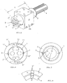
- Fig.1,2 are typical, octagonal profile bars 1 in Section shown as for the compilation of Robotic arms arranged support frames are used.
- the profile bars 1 with each other by so-called Clamping pieces KS are connected, which have no special explanation need, because they are known and not immediate here Interest.
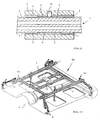
- the in Fig. 10 rod connectors shown in the introduction the aforementioned clamp-turntable combinations, with which the gripper G shown is not immediate to the axes A of the profile rods 1 continuously rotatable can be.
- profile bars shown in section in Fig. 1,2 1 are cross-sectionally octagonal profiles that essentially only by their cross-sectional size and distinguish the number of their grooves 2.
- Overall stability or rigidity of such from the profile bars Assembled carrying frames have the profile bars relatively thick walls, i.e. how they relate to each Diameters are shown, for example.
- an at least externally cylindrical sleeve 3 is essential, which is provided on its inner circumferential surface 4 with two diametrically opposed notches 5, at least two Corresponding notch grooves 6 are provided diametrically opposite on the outer circumferential surface of the respective profile rod 1, which are aligned with the notch grooves 5 of the sleeve 3.
- cylindrical pins 7, which lie against the surfaces 5 ', 6' of the notches 5, 6, are arranged according to the invention. Concerning. the assignment of the pins 7 to the notch grooves 5, 6 is referred to the greatly enlarged illustration in FIG. 8.
- the pins 7 are used in conjunction with the notches 5,6 triangular in the cross-section both for exact centering of the sleeve 3 to the axis A of the profile rod 1 and at the same time for securing the sleeve 3 against rotation with respect to the profile rod 1.
- the sleeve 3 forming the pivot bearing according to the invention has two radially inward facing, radially opposing and in webs 2 of the profile bar 1 matching webs 8 is provided, the grooves 2 and the webs 8 being arranged offset to the notch pairs 5,6.
- the anti-rotation device is thus taken over in particular by the webs 8 engaging in the grooves 2, ie the notch grooves and the dowel pins 7 can in this case be dimensioned smaller, as in the embodiment according to FIG. 3.
- the exemplary embodiment according to FIG. 4 also serves for illustration an embodiment in which the sleeve 3 with its inner surface 4 'essentially the polygonal cross-sectional shape the profile rod 1 is adapted.
- FIG. 5 shows the arrangement of the pivot bearing according to the invention or the sleeve 3 on a profile rod 1 illustrates in perspective, wherein also a clamped on the sleeve 3 fixed Adapter AR is shown with a tool can be attached.
- Adapter AR can fixed in any radial position on the sleeve 3 become.
- the length L of the sleeve 3 corresponds advantageously at least twice the size of their diameter by one such adapter AR also different in the axial direction to be able to position.
- the sleeve 6 is a special embodiment of the sleeve in this respect 3, as this consists of two identical shell halves 3 'is formed, which, as shown, at their joints can be entangled or busy and also there in the area conjugated diameter D 'to each other by means of dashed lines only shown screws 10 are screwed.
- the Heads of the screws 10 must of course in the Screw holes 11 must be accommodated, i.e., they may do not protrude the outer peripheral surface 12 of the sleeve 3.
- FIG. 7 shows an embodiment of the invention clarifies which is a cylindrical tube acts as a profile rod 1, the sleeve 3 despite its inner Excess 13 is exactly centered, which also this embodiment by driving in or pushing in of the two cylindrical pins 7 into those also present here Core groove pairs 5.6 is effected.
- Oversize 13 which is of the order of 1 to 2 mm can, of course, is also the case with the other exemplary embodiments between profile rod 1 and sleeve 3.
- Figure 9 is a section along line IX-IX in Figure 5 by the Pivot bearing shown. It follows that the notches 5.6 both on the sleeve 3 and on the profile rod 1 over the entire length of which is extended. Not with the pins 7 a length corresponding to the length L of the sleeve 3 in the core groove pairs have to drive in with a light press fit the pins 7 in relation to the length of the notches 5 in the Dimension sleeve 3 shorter and from both sides into the notch pairs inserted. In addition, as also from Fig. 9 can be seen for an additional axial fixing of the sleeve 3 provided on the profile rod 1 by a countersunk screw 15 become.
- FIG. 10 The exemplary embodiment shown in FIG. 10 is concerned itself, as mentioned in the introduction, to a support frame TG Clamping pieces KS assembled profile bars 1.
- This Support frame TG is from a robot arm, not shown here worn, on which it is arranged by means of a centrally Connection plate 14 is attached. Since it's just a Example of a support frame TG known type are on this example, no pivot bearing shown according to the invention.
Landscapes
- Engineering & Computer Science (AREA)
- Mechanical Engineering (AREA)
- Robotics (AREA)
- General Engineering & Computer Science (AREA)
- Pivots And Pivotal Connections (AREA)
Applications Claiming Priority (2)
| Application Number | Priority Date | Filing Date | Title |
|---|---|---|---|
| US501878 | 2000-02-10 | ||
| US09/501,878 US6318926B1 (en) | 2000-02-10 | 2000-02-10 | Pivot bearing provided on support structures formed of shaped bars |
Publications (2)
| Publication Number | Publication Date |
|---|---|
| EP1123783A2 true EP1123783A2 (fr) | 2001-08-16 |
| EP1123783A3 EP1123783A3 (fr) | 2002-03-20 |
Family
ID=23995386
Family Applications (1)
| Application Number | Title | Priority Date | Filing Date |
|---|---|---|---|
| EP00106300A Withdrawn EP1123783A3 (fr) | 2000-02-10 | 2000-03-23 | Ensemble pivotant pour positionner des outils sur des structures support |
Country Status (2)
| Country | Link |
|---|---|
| US (1) | US6318926B1 (fr) |
| EP (1) | EP1123783A3 (fr) |
Cited By (2)
| Publication number | Priority date | Publication date | Assignee | Title |
|---|---|---|---|---|
| WO2007120795A3 (fr) * | 2006-04-13 | 2008-04-17 | Norgren Automotive Inc | Appareil permettant de positionner et soutenir avec précision un outillage modulaire |
| WO2025104068A1 (fr) * | 2023-11-13 | 2025-05-22 | TRUMPF Werkzeugmaschinen SE + Co. KG | Dispositif de manutention et procédé de manutention pour manipuler un matériau en forme de plaque |
Families Citing this family (3)
| Publication number | Priority date | Publication date | Assignee | Title |
|---|---|---|---|---|
| WO2004103652A2 (fr) * | 2003-05-21 | 2004-12-02 | Societe Amg | Organe prehenseur pour la retenue d’une piece a deplacer par un manipulateur, agence en structure etagee comprenant une poutre sur laquelle sont articules des bras porteurs d’une tete de retenue |
| FR2855089B1 (fr) * | 2003-05-21 | 2006-09-22 | A M G | Organe prehenseur pour la retenue d'une piece a deplacer par un manipulateur, agence en structure etagee comprenant une poutre sur laquelle sont articules des bras porteurs d'une tete de retenue |
| AT527495B1 (de) * | 2024-03-11 | 2025-03-15 | Loci Design Kg | Verbindungsvorrichtung |
Citations (2)
| Publication number | Priority date | Publication date | Assignee | Title |
|---|---|---|---|---|
| US4032245A (en) | 1976-07-09 | 1977-06-28 | Gramor Machine Company | Agricultural equipment clamp |
| GB2275737A (en) | 1993-03-05 | 1994-09-07 | Donald Lee Hufford | Instrument support boom assemblies and unions thereof |
Family Cites Families (6)
| Publication number | Priority date | Publication date | Assignee | Title |
|---|---|---|---|---|
| US3147829A (en) * | 1960-06-15 | 1964-09-08 | Sealing Corp Of America | Telescoping elevating support |
| CA893414A (en) * | 1970-08-25 | 1972-02-22 | Beautiline Limited | Connector for joining tubular members |
| DE4317579A1 (de) * | 1993-05-27 | 1994-12-01 | Kurt Ehrenberg | Spannverbindung zwischen einer Hülse und einer Welle |
| DE29501158U1 (de) * | 1995-01-25 | 1995-03-30 | Aktiebolaget Electrolux Corporate Patents & Trademarks, Stockholm | Arretiervorrichtung für eine Antriebswelle |
| GB2304792A (en) * | 1995-09-08 | 1997-03-26 | Nastech Europ Ltd | Snap connection system |
| DE29905687U1 (de) * | 1999-03-27 | 1999-07-08 | DE-STA-CO Metallerzeugnisse GmbH, 61449 Steinbach | Trageinrichtung |
-
2000
- 2000-02-10 US US09/501,878 patent/US6318926B1/en not_active Expired - Fee Related
- 2000-03-23 EP EP00106300A patent/EP1123783A3/fr not_active Withdrawn
Patent Citations (2)
| Publication number | Priority date | Publication date | Assignee | Title |
|---|---|---|---|---|
| US4032245A (en) | 1976-07-09 | 1977-06-28 | Gramor Machine Company | Agricultural equipment clamp |
| GB2275737A (en) | 1993-03-05 | 1994-09-07 | Donald Lee Hufford | Instrument support boom assemblies and unions thereof |
Cited By (3)
| Publication number | Priority date | Publication date | Assignee | Title |
|---|---|---|---|---|
| US8108978B2 (en) | 2005-07-06 | 2012-02-07 | Norgren Automation Solutions, Inc. | Apparatus for accurately positioning and supporting modular tooling |
| WO2007120795A3 (fr) * | 2006-04-13 | 2008-04-17 | Norgren Automotive Inc | Appareil permettant de positionner et soutenir avec précision un outillage modulaire |
| WO2025104068A1 (fr) * | 2023-11-13 | 2025-05-22 | TRUMPF Werkzeugmaschinen SE + Co. KG | Dispositif de manutention et procédé de manutention pour manipuler un matériau en forme de plaque |
Also Published As
| Publication number | Publication date |
|---|---|
| EP1123783A3 (fr) | 2002-03-20 |
| US6318926B1 (en) | 2001-11-20 |
Similar Documents
| Publication | Publication Date | Title |
|---|---|---|
| EP1330611B1 (fr) | Bras telescopique | |
| DE19521710B4 (de) | Panoramakopf für optische Geräte, insbesondere für Fotoapparate | |
| EP0626604A2 (fr) | Tube endoscopique flexible | |
| EP0614035A1 (fr) | Support fixé au plafond | |
| EP3122520A1 (fr) | Bras de robot et kit de montage | |
| EP1819480B1 (fr) | Dispositif de positionnement de piece | |
| EP2700608A1 (fr) | Plaque de montage et colonne élévatrice | |
| DE69110689T2 (de) | Kardangelenk für spielzeugkonstruktion. | |
| WO2000045991A1 (fr) | Machine a chaine cinematique parallele | |
| DE102020125969A1 (de) | Linearer ausdehnungsmechanismus | |
| WO1999008832A1 (fr) | Dispositif pour deplacer et positionner un objet dans un plan | |
| DE102012108031A1 (de) | Halter für eine Fügevorrichtung | |
| AT393303B (de) | Vorrichtung zum verbinden von bauteilen | |
| EP1123783A2 (fr) | Ensemble pivotant pour positionner des outils sur des structures support | |
| EP2926759A2 (fr) | Bras de support destiné à positionner un instrument médical ou un appareil médical | |
| EP1249406B1 (fr) | Dispositif de renvoi pour convoyeur | |
| EP0585563B1 (fr) | Dispositif pour la génération d'un mouvement synchrone de translation/rotation | |
| DE3042427C2 (de) | Doppelschneckenstrangpresse zum Verarbeiten von thermoplastischen Formmassen, insbesondere Kunststoffen | |
| EP0034640B1 (fr) | Mécanisme à vis | |
| EP2031175A1 (fr) | Elément latéral pour un boîtier de store | |
| EP1650854A2 (fr) | Module d'avance linéaire avec corps de guidage et cantilever pour ça | |
| DE10015186B4 (de) | Objektivfassung | |
| AT410121B (de) | Verbindungselement für rahmenprofile | |
| EP1988311A2 (fr) | Palier et actionneur linéaire équipé d'un tel palier | |
| EP1431604A1 (fr) | Joint universel avec élément de retenue. |
Legal Events
| Date | Code | Title | Description |
|---|---|---|---|
| PUAI | Public reference made under article 153(3) epc to a published international application that has entered the european phase |
Free format text: ORIGINAL CODE: 0009012 |
|
| AK | Designated contracting states |
Kind code of ref document: A2 Designated state(s): AT BE CH CY DE DK ES FI FR GB GR IE IT LI LU MC NL PT SE |
|
| AX | Request for extension of the european patent |
Free format text: AL;LT;LV;MK;RO;SI |
|
| PUAL | Search report despatched |
Free format text: ORIGINAL CODE: 0009013 |
|
| AK | Designated contracting states |
Kind code of ref document: A3 Designated state(s): AT BE CH CY DE DK ES FI FR GB GR IE IT LI LU MC NL PT SE |
|
| AX | Request for extension of the european patent |
Free format text: AL;LT;LV;MK;RO;SI |
|
| AKX | Designation fees paid | ||
| REG | Reference to a national code |
Ref country code: DE Ref legal event code: 8566 |
|
| STAA | Information on the status of an ep patent application or granted ep patent |
Free format text: STATUS: THE APPLICATION IS DEEMED TO BE WITHDRAWN |
|
| 18D | Application deemed to be withdrawn |
Effective date: 20020921 |