EP1123790A2 - Procédé pour l'ébavurage d'objets annulaires en caoutchouc - Google Patents
Procédé pour l'ébavurage d'objets annulaires en caoutchouc Download PDFInfo
- Publication number
- EP1123790A2 EP1123790A2 EP01102022A EP01102022A EP1123790A2 EP 1123790 A2 EP1123790 A2 EP 1123790A2 EP 01102022 A EP01102022 A EP 01102022A EP 01102022 A EP01102022 A EP 01102022A EP 1123790 A2 EP1123790 A2 EP 1123790A2
- Authority
- EP
- European Patent Office
- Prior art keywords
- waste material
- article
- cutting tool
- assembly
- tire
- Prior art date
- Legal status (The legal status is an assumption and is not a legal conclusion. Google has not performed a legal analysis and makes no representation as to the accuracy of the status listed.)
- Withdrawn
Links
- 238000000034 method Methods 0.000 title claims abstract description 23
- 239000002699 waste material Substances 0.000 claims abstract description 89
- 230000000149 penetrating effect Effects 0.000 claims abstract description 10
- 239000011324 bead Substances 0.000 description 39
- 230000007246 mechanism Effects 0.000 description 23
- 208000015943 Coeliac disease Diseases 0.000 description 13
- 229920001971 elastomer Polymers 0.000 description 8
- 230000000712 assembly Effects 0.000 description 6
- 238000000429 assembly Methods 0.000 description 6
- 238000002347 injection Methods 0.000 description 5
- 239000007924 injection Substances 0.000 description 5
- 238000001746 injection moulding Methods 0.000 description 4
- 238000000465 moulding Methods 0.000 description 3
- 230000035515 penetration Effects 0.000 description 2
- 238000013329 compounding Methods 0.000 description 1
- 239000000806 elastomer Substances 0.000 description 1
- 239000000945 filler Substances 0.000 description 1
- 239000000463 material Substances 0.000 description 1
- 239000010813 municipal solid waste Substances 0.000 description 1
- 238000004064 recycling Methods 0.000 description 1
Images




Classifications
-
- B—PERFORMING OPERATIONS; TRANSPORTING
- B29—WORKING OF PLASTICS; WORKING OF SUBSTANCES IN A PLASTIC STATE IN GENERAL
- B29C—SHAPING OR JOINING OF PLASTICS; SHAPING OF MATERIAL IN A PLASTIC STATE, NOT OTHERWISE PROVIDED FOR; AFTER-TREATMENT OF THE SHAPED PRODUCTS, e.g. REPAIRING
- B29C37/00—Component parts, details, accessories or auxiliary operations, not covered by group B29C33/00 or B29C35/00
- B29C37/02—Deburring or deflashing
-
- B—PERFORMING OPERATIONS; TRANSPORTING
- B29—WORKING OF PLASTICS; WORKING OF SUBSTANCES IN A PLASTIC STATE IN GENERAL
- B29L—INDEXING SCHEME ASSOCIATED WITH SUBCLASS B29C, RELATING TO PARTICULAR ARTICLES
- B29L2030/00—Pneumatic or solid tyres or parts thereof
- B29L2030/001—Beads
-
- Y—GENERAL TAGGING OF NEW TECHNOLOGICAL DEVELOPMENTS; GENERAL TAGGING OF CROSS-SECTIONAL TECHNOLOGIES SPANNING OVER SEVERAL SECTIONS OF THE IPC; TECHNICAL SUBJECTS COVERED BY FORMER USPC CROSS-REFERENCE ART COLLECTIONS [XRACs] AND DIGESTS
- Y10—TECHNICAL SUBJECTS COVERED BY FORMER USPC
- Y10S—TECHNICAL SUBJECTS COVERED BY FORMER USPC CROSS-REFERENCE ART COLLECTIONS [XRACs] AND DIGESTS
- Y10S83/00—Cutting
- Y10S83/914—Flash trimming
-
- Y—GENERAL TAGGING OF NEW TECHNOLOGICAL DEVELOPMENTS; GENERAL TAGGING OF CROSS-SECTIONAL TECHNOLOGIES SPANNING OVER SEVERAL SECTIONS OF THE IPC; TECHNICAL SUBJECTS COVERED BY FORMER USPC CROSS-REFERENCE ART COLLECTIONS [XRACs] AND DIGESTS
- Y10—TECHNICAL SUBJECTS COVERED BY FORMER USPC
- Y10S—TECHNICAL SUBJECTS COVERED BY FORMER USPC CROSS-REFERENCE ART COLLECTIONS [XRACs] AND DIGESTS
- Y10S83/00—Cutting
- Y10S83/929—Particular nature of work or product
- Y10S83/951—Rubber tyre
-
- Y—GENERAL TAGGING OF NEW TECHNOLOGICAL DEVELOPMENTS; GENERAL TAGGING OF CROSS-SECTIONAL TECHNOLOGIES SPANNING OVER SEVERAL SECTIONS OF THE IPC; TECHNICAL SUBJECTS COVERED BY FORMER USPC CROSS-REFERENCE ART COLLECTIONS [XRACs] AND DIGESTS
- Y10—TECHNICAL SUBJECTS COVERED BY FORMER USPC
- Y10T—TECHNICAL SUBJECTS COVERED BY FORMER US CLASSIFICATION
- Y10T83/00—Cutting
- Y10T83/04—Processes
- Y10T83/0405—With preparatory or simultaneous ancillary treatment of work
- Y10T83/0419—By distorting within elastic limit
- Y10T83/0424—By stretching
-
- Y—GENERAL TAGGING OF NEW TECHNOLOGICAL DEVELOPMENTS; GENERAL TAGGING OF CROSS-SECTIONAL TECHNOLOGIES SPANNING OVER SEVERAL SECTIONS OF THE IPC; TECHNICAL SUBJECTS COVERED BY FORMER USPC CROSS-REFERENCE ART COLLECTIONS [XRACs] AND DIGESTS
- Y10—TECHNICAL SUBJECTS COVERED BY FORMER USPC
- Y10T—TECHNICAL SUBJECTS COVERED BY FORMER US CLASSIFICATION
- Y10T83/00—Cutting
- Y10T83/343—With means to deform work temporarily
Definitions
- This invention relates to a method for removing waste material from an annular, elastomeric article. More particularly, this invention relates to a method for removing a gate from a tire bead apex assembly.
- molded articles has become increasingly common in many industries. In the tire industry, better compounding has resulted in the ability to better adhere molded, precured articles with uncured elastomers.
- This advance allows tire manufacturers to mold and precure certain components of a tire prior to assembly of the tire on a building drum.
- One such component is the tire bead apex assembly.
- the rubber portions of the assembly Prior to molding and precuring the tire bead apex assembly, the rubber portions of the assembly were made of unvulcanized rubber. Due to the relative thickness of each component, extra curing time was required to cure the rubber of these components. This extra curing time has been eliminated with the use of molded and precured assemblies.
- a precured tire bead apex assembly provides additional benefits.
- An uncured tire bead apex assembly will likely distort during the tire building process, during transportation of the tire to the curing press, and while curing. By precuring the tire bead apex assembly, better uniformity is achieved. Since a precured tire bead apex assembly will not distort, the use of precured assemblies allows tire builders to accurately place ply ends and to determine a precise ply path around the assembly.
- the use of a precured tire bead apex assembly provides many advantages, there is a need to mass-produce these assemblies. Molding and precuring large amounts of these assemblies can easily be done with the proper injection molding machines; however, a problem occurs in readying these assemblies for use in a tire.
- the article After molding the article, the article generally has waste material attached to it.
- the precured tire bead apex assembly is removed from the injection molding machine, the assembly has a gate attached to it.
- the gate is a ring of cured rubber waste produced during the injection molding process.
- the tire bead apex assembly cannot be used in a tire until this waste material is removed.
- the gate on an injection molded tire bead apex assembly may extend inward from the bead portion of the assembly. When mounted in a tire, the bead portion of the assembly is located radially inwardly of the apex portion of the assembly.
- the gate on the injection molded tire bead apex assembly is large enough to make removal difficult.
- a typical gate can have a thickness of approximately one-eighth of an inch (3.175 mm) and can extend approximately one inch (25.4 mm) from the bead portion of the assembly around the entire circumference of the assembly.
- Each gate may have a plurality of sprues that extend from the gate surface. The sprues are cured rubber waste from rubber left in the runners of the injection molding machine. Since the sprues are part of the gate, they are removed from the tire bead apex assembly when the gate is removed.
- the waste material is torn off of the article when the article is removed from the mold. This generally occurs when the waste material is very thin and can easily and cleanly be torn off of the injection molded article.
- an additional process step is needed to remove the waste material.
- the current method of removing a gate from an injection molded tire bead apex assembly is to remove the gate by hand. After the gate is removed from the mold, it is manually hung on a hook by its inside diameter, the bead portion. An operator then manually removes the gate with a cutting tool, such as a razor blade. Manual removal of the waste material becomes very expensive and inefficient when large quantities of articles are manufactured. Manual removal of the waste material also leads to non-uniformity arising from the difficulty in assuring a clean and uniform cut along the entire edge of the article. Additionally, if the cut is too close to the article, the article can be damaged, and if the cut is not close enough to the article, portions of the waste material remain on the article.
- This invention relates to a method for removing waste material from an annular, elastomeric article.
- the method includes the steps of: securing at least a portion of the annular, elastomeric article; securing at least a portion of the waste material; penetrating the waste material with a cutting tool; and guiding the cutting tool through the waste material.
- the method is characterized by the step of stretching the waste material prior to guiding the cutting tool.
- Fig. 1 is a cross-sectional view of a portion of an annular, elastomeric article 10 prior to removal of the waste material.
- the article 10 depicted is a portion of a tire bead apex assembly 12.
- the bead 14 is located in the bead portion 16 of the assembly 12.
- the bead portion 16 of the assembly 12 is located radially inwardly of the apex portion 18 of the assembly 12.
- the bead portion 16 has a bead toe side 20 and a bead heel side 22.
- the waste material, a gate 24, extends from the bead toe side 20 of the assembly 12 and extends at least partially in a radially inwardly direction.
- the waste material In order for the tire bead apex assembly 12 to be used in a tire, the waste material must be removed from the assembly 12 along an edge 28 of the assembly 12. Generally, the waste material is annular in shape and extends completely around the circumference of the annular, elastomeric article 10.
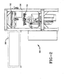
- Fig. 2 shows a side view of an apparatus 30 for removing the waste material from the annular, elastomeric article 10.
- the apparatus 30 has a frame 36 which supports both a first tooling assembly 32 and a second tooling assembly 34.
- the first tooling assembly 32 is mounted on at least one rail 38.
- the rail 38 extends out a side of the apparatus 30 to a position above a disposal area, such as a trash can or a recycling bin.
- the first tooling assembly 32 can be shuttled on the rail 38 between a position in the center of the apparatus 30 and a position external to the frame 36 on the extension of the rail 38.
- the first tooling assembly 32 When positioned for the removal of the waste material, the first tooling assembly 32 is centered in the apparatus 30.
- the center of the first tooling assembly 32 is directly above the center of the second tooling assembly 34.
- the apparatus 30 has at least a portion of a first mechanism and a second mechanism.
- the first mechanism is used to secure at least a portion of the annular, elastomeric article 10.
- at least of portion of each third of the article 10 is simultaneously secured.
- Each third consists of a separate 120 degree section of the article 10.
- the second mechanism is used to secure at least a portion of the waste material. If the waste material extends around the entire circumference of the article 10, it is preferred to simultaneously secure at least a portion of each third of the waste material.
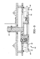
- Fig. 3 shows a detailed side view of the first tooling assembly 32.
- the first tooling assembly 32 contains a portion of both the first mechanism and the second mechanism.
- the portion of the first mechanism located on the first tooling assembly 32 is a register surface 40.
- the portion of the second mechanism located on the first tooling assembly 32 is the first clamp plate 42.
- the register surface 40 is separated from the first clamp plate 42 by an open space 44.
- the first clamp plate 42 is connected to a cylinder 46 which allows the first clamp plate 42 to move inwardly toward the cylinder 46.
- the cylinder 46 limits the amount of movement with the use of a spring, an pneumatic cylinder, or a similar device.
- the first and second mechanisms can have different embodiments, including jaws located entirely on one of the tooling assemblies 32, 34, for securing the article 10 and the waste material, respectively.
- the article 10 is secured against the register surface 40 by an external device, such as the securing arm 54 shown in Fig. 7.
- a separate machine can be used to transfer the article 10 to the apparatus 30. The machine then extends its arm 54 toward the register surface 40 to secure the article 10 against the register surface 40.
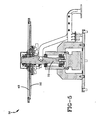
- Fig. 5 shows a detailed side view of the second tooling assembly 34.
- the second tooling assembly 34 contains the remaining portion of the second mechanism, the second clamp plate 48.
- the second clamp plate 48 moves toward and away from the first clamp plate 42.
- the second clamp plate 48 moves toward the first clamp plate 42 to secure at least a portion of the waste material.
- Fig. 7 shows a tire bead apex assembly 12 having a gate 24. The tire bead apex assembly 12 is at least partially secured between the register surface 40 and the securing arm 54.
- At least a portion of the gate 24 becomes secured when it is compressed between the first clamp plate 42 and the second clamp plate 48.
- the second clamp plate 48 continues to move toward the first clamp plate 42 moving both toward the cylinder 46 of the first tooling assembly 32. This action stretches the gate 24 until the cylinder 46 provides sufficient resistance to stop the movement. As a result, the gate is stretched up to three quarters of an inch (19.05 mm). The amount of stretch can be adjusted by adjusting the resistance of the cylinder 46.
- the waste material should be stretched a distance sufficient to simultaneously apply some degree of tension to the unsecured portions of the waste material.
- the unsecured portions of the waste material are those portions not being secured or compressed by the second mechanism.
- stretching the unsecured portions of the waste material is performed by securing at least a portion of the waste material around all 360 degrees of the annular article 10 and causing uniform stretching to the waste material.
- the waste material will typically need to be secured in at least three positions, two of which are separated by more than 180 degrees. Additionally, the stretching of the waste material should be limited to prevent tearing after penetration of the waste material by the cutting tool 52.
- the second tooling assembly 34 has a tooling plate 50 located directly under the second clamp plate 48. Each cutting tool 52 is attached to the tooling plate 50.
- the apparatus 30 can have a single cutting tool 52 or multiple cutting tools 52.
- the ideal shape of the tooling plate 50 is circular and the plate is rotated about a central shaft 72 that aligns with the central axis of the annular, elastomeric article 10. This rotation imparts a circumferential force to move the cutting tool 52 through the waste material completely around the annular article 10.
- Fig. 6 shows a view an embodiment of a cutting tool 52.
- This cutting tool 52 has a blade 56 with a sharp point 58. A laser, a water-jet, or any other alternative can be used in place of the blade 56.
- the cutting tool 52 also has a penetrating mechanism 60 used to penetrate the waste material.
- the penetrating mechanism 60 shown is a pneumatic cylinder but other like mechanisms may be used.
- the cutting tool 52 also has a positioning device 62 for properly positioning the blade 56.
- the positioning device 62 shown is a pair of rollers.
- An extending mechanism 64 extends until the positioning device 62 contacts the article 10.
- the blade 56 is positioned a predetermined distance from the positioning device 62 so that it will be properly positioned to penetrate the waste material when the positioning device is in contact with the article 10.
- the penetrating mechanism 60 forces at least the sharp point 58 of the blade 56 completely through the waste material. If a laser or a water-jet is used, the penetrating mechanism 60 is not necessary.
- the cutting tool 52 is guided along the edge 28 of the article 10 until the waste material is removed. The guiding is done by applying a radial force to the cutting tool 52 to ensure contact between a positioning device 62 and the article 10, and by applying a circumferential force to the cutting tool 52 to move it through the waste material.
- the first mechanism releases the article 10 and the article 10 is transferred away from the apparatus 30.
- the second mechanism may also be released and the waste material disposed of manually or automatically.
- the first tooling assembly 32 can be used to automatically dispose of the waste material if the waste material contains sprues 26, such as a gate 24 of a tire bead apex assembly 12.
- the first tooling assembly 32 may have a locking plate 66 located directly above the first clamp plate 42.
- the first clamp plate 42 has a plurality of holes 68, each located to accept a respective sprue 26.
- the locking plate 66 has a plurality of openings 70 which correspond with some of the holes 68 in the first clamp plate 42.
- each sprue 26 is received by both a respective hole 68 in the first clamp plate 42 and a respective opening 70 in the locking plate 66.
- the locking plate 66 rotates to lock each sprue 26 between a surface forming each hole 68 and a surface forming each opening 70.
- the first mechanism is released and the article 10 is removed.
- the second tooling assembly 34 retracts away from the first tooling assembly 32. At this time, the removed waste material is attached to the first tooling assembly 32 by the locked sprues 26.
- the first tooling assembly 32 is shuttled on the rail 38 out a side of the apparatus 30 to the position above a disposal area.
- the locking plate 66 is moved back to its original position to release the sprues 26 and the removed waste material is dropped into the disposal area. If the entire second mechanism is located on the first tooling assembly 32, there is no need for a locking plate 66 or for sprues 26 as the second mechanism can secure the waste material until the first tooling assembly 32 has shuttled to the position above the disposal area. After the removed waste material is dropped from the first tooling assembly 32, the first tooling assembly 32 resets to its original position to accept another article 10.
- the method of removing waste material from an annular, elastomeric article 10 includes the steps of: securing at least a portion of the article 10; securing at least a portion of the waste material; penetrating the waste material with a cutting tool 52; guiding the cutting tool 52 through the waste material; and stretching the waste material prior to guiding the cutting tool 52.
- the waste material is simultaneously stretched in at least three locations. When the waste material is stretched, the material is stretched a distance sufficient to simultaneously apply a tension to portions of the waste material between the stretching locations. However, the amount of stretch of the waste material is limited to prevent tearing of the waste material after penetration with the cutting tool 52.
- the step of penetrating the waste material with the cutting tool 52 may include properly positioning the cutting tool 52 and applying a force to push at least a portion of the cutting tool 52 completely through the waste material.
- the cutting tool 52 has a positioning device 62 that is located a predetermined distance from the blade 56 of the cutting tool 52.
- the cutting tool 52 is extended toward the article 10 until the positioning device 62 contacts the article 10.
- the cutting tool 52 may be guided through the waste material by applying a radial force to ensure continuous contact between the positioning device 62 and the article 10, and applying a circumferential force to the cutting tool 52 to move it through the waste material.
Landscapes
- Physics & Mathematics (AREA)
- Thermal Sciences (AREA)
- Processing And Handling Of Plastics And Other Materials For Molding In General (AREA)
- Tyre Moulding (AREA)
- Lining Or Joining Of Plastics Or The Like (AREA)
- Moulds For Moulding Plastics Or The Like (AREA)
Applications Claiming Priority (2)
| Application Number | Priority Date | Filing Date | Title |
|---|---|---|---|
| US501016 | 2000-02-09 | ||
| US09/501,016 US6439090B1 (en) | 2000-02-09 | 2000-02-09 | Method for removing waste material from an annular, elastomeric article |
Publications (2)
| Publication Number | Publication Date |
|---|---|
| EP1123790A2 true EP1123790A2 (fr) | 2001-08-16 |
| EP1123790A3 EP1123790A3 (fr) | 2003-04-16 |
Family
ID=23991805
Family Applications (1)
| Application Number | Title | Priority Date | Filing Date |
|---|---|---|---|
| EP01102022A Withdrawn EP1123790A3 (fr) | 2000-02-09 | 2001-01-30 | Procédé pour l'ébavurage d'objets annulaires en caoutchouc |
Country Status (4)
| Country | Link |
|---|---|
| US (1) | US6439090B1 (fr) |
| EP (1) | EP1123790A3 (fr) |
| JP (1) | JP2001252928A (fr) |
| BR (1) | BR0100226A (fr) |
Cited By (2)
| Publication number | Priority date | Publication date | Assignee | Title |
|---|---|---|---|---|
| CN104260251A (zh) * | 2014-09-04 | 2015-01-07 | 江苏益尔机电有限公司 | 改善修边效果的轮胎修边装置及轮胎修边工艺 |
| CN109291344A (zh) * | 2018-09-21 | 2019-02-01 | 江苏准信自动化科技股份有限公司 | 一种全自动密封圈修边机 |
Families Citing this family (2)
| Publication number | Priority date | Publication date | Assignee | Title |
|---|---|---|---|---|
| US7073552B2 (en) * | 2002-12-20 | 2006-07-11 | The Goodyear Tire & Rubber Company | Tire preparation ply manufacturing apparatus and method |
| KR100593014B1 (ko) | 2004-06-15 | 2006-06-26 | 금호타이어 주식회사 | 비드-에이펙스 분리기 |
Family Cites Families (34)
| Publication number | Priority date | Publication date | Assignee | Title |
|---|---|---|---|---|
| US1314029A (en) * | 1919-08-26 | Machine for trimming and finishing rubber gaskets and similar articles | ||
| US1206946A (en) * | 1910-03-07 | 1916-12-05 | Firm Of Henri Levy | Apparatus for cutting waste from embroideries. |
| US1214295A (en) * | 1914-09-08 | 1917-01-30 | Goodrich Co B F | Method and apparatus for producing rubber molding-blanks. |
| US1273526A (en) * | 1916-06-17 | 1918-07-23 | Goodyear Tire & Rubber | Cutting or trimming machine. |
| US1395055A (en) * | 1917-11-03 | 1921-10-25 | Goodyear Tire & Rubber | Tire-making machine |
| GB164787A (en) * | 1920-01-12 | 1921-06-13 | Dunlop Rubber Co | Improvements in or relating to machines for making pneumatic tyre covers or casings |
| US1721298A (en) * | 1925-11-19 | 1929-07-16 | Goodyear Tire & Rubber | Tire-trimming machine |
| US1994178A (en) * | 1932-09-07 | 1935-03-12 | Davol Rubber Co | Method and apparatus for trimming molded articles |
| US2036787A (en) * | 1933-12-09 | 1936-04-07 | Charles C Zabriskie | Method of making windshield wipers |
| US2293721A (en) * | 1941-08-11 | 1942-08-25 | Gen Tire & Rubber Co | Method of and apparatus for cutting and splicing thick rubber stock and the like |
| GB713260A (en) * | 1951-06-16 | 1954-08-11 | Dunlop Rubber Co | Apparatus for trimming moulding spew from tyre covers |
| US2866501A (en) * | 1956-08-20 | 1958-12-30 | Goodyear Tire & Rubber | Apparatus for siping tires |
| US3171317A (en) * | 1959-12-04 | 1965-03-02 | United Shoe Machinery Corp | Flash trimming machines |
| US3545321A (en) * | 1963-05-13 | 1970-12-08 | Vernon A Phelps | Close tolerance gasket making |
| DE1260127B (de) * | 1965-06-01 | 1968-02-01 | Continental Gummi Werke Ag | Maschine zum Entfernen der Austriebe an einem Gummireifen fuer Fahrzeuge |
| US3454690A (en) * | 1966-05-16 | 1969-07-08 | Haskon Inc | Plastic container construction |
| US3461756A (en) * | 1968-12-04 | 1969-08-19 | Mojonnier Inc Albert | Method for trimming plastic preforms |
| US3903948A (en) | 1973-08-13 | 1975-09-09 | Goodyear Tire & Rubber | Transverse flash breaking in tire manufacture |
| JPS5268594A (en) * | 1975-12-05 | 1977-06-07 | Toyo Seikan Kaisha Ltd | Method and device for cutting open rattannlike package |
| US4181482A (en) | 1976-07-19 | 1980-01-01 | Caterpillar Tractor Co. | Tire tread forming apparatus |
| US4181488A (en) | 1976-07-19 | 1980-01-01 | Caterpillar Tractor Co. | Tire tread forming mold body |
| DE2750232A1 (de) | 1977-11-10 | 1979-05-17 | Desma Werke Gmbh | Form, insbesondere spritzgiessform, zum herstellen von formlingen aus kautschuk, insbesondere apex-ringen |
| US4326325A (en) * | 1980-07-21 | 1982-04-27 | Rca Corporation | Method and apparatus for deflashing molded recorded discs |
| US4617849A (en) * | 1984-06-22 | 1986-10-21 | Ligon James T | Washer cutting procedure |
| JPS63288602A (ja) * | 1987-05-22 | 1988-11-25 | Nippon Plast Co Ltd | 成形品のバリ取装置 |
| CA1318237C (fr) * | 1988-01-29 | 1993-05-25 | Masao Hirao | Dispositif pour couper et oter les emballages |
| US4960022A (en) * | 1989-03-07 | 1990-10-02 | Chuang Kuo C | Plastic film cutter |
| US5069594A (en) * | 1990-05-15 | 1991-12-03 | Ideas In Motion | Bottle debagging and feeding apparatus |
| IT1241286B (it) | 1990-11-20 | 1993-12-29 | Gilardini Spa | Metodo di fabbricazione di un filtro per aria, filtro cosi' ottenuto e apparecchiatura per l'attuazione di tale metodo |
| IT1247883B (it) | 1991-05-03 | 1995-01-05 | Devi Spa | Procedimento e macchina per lo stampaggio di materiale plastico accoppiato |
| US5699706A (en) * | 1991-09-11 | 1997-12-23 | Temper Corporation | Apparatus for cutting a non-metallic magnetic component from a strip of non-metallic magnetic material useable on a rotor or the like |
| DE4219051C2 (de) * | 1992-06-11 | 2002-09-19 | Kettner Gmbh | Vorrichtung zum Entfernen von Etiketten von Behältern |
| US6086295A (en) * | 1997-06-30 | 2000-07-11 | Novak; Norm | Automated flash removing apparatus |
| US6142044A (en) * | 1999-09-03 | 2000-11-07 | Lucent Technologies, Inc. | System for trimming excess material |
-
2000
- 2000-02-09 US US09/501,016 patent/US6439090B1/en not_active Expired - Fee Related
-
2001
- 2001-01-30 EP EP01102022A patent/EP1123790A3/fr not_active Withdrawn
- 2001-01-31 BR BR0100226-0A patent/BR0100226A/pt not_active IP Right Cessation
- 2001-02-06 JP JP2001029715A patent/JP2001252928A/ja active Pending
Cited By (3)
| Publication number | Priority date | Publication date | Assignee | Title |
|---|---|---|---|---|
| CN104260251A (zh) * | 2014-09-04 | 2015-01-07 | 江苏益尔机电有限公司 | 改善修边效果的轮胎修边装置及轮胎修边工艺 |
| CN109291344A (zh) * | 2018-09-21 | 2019-02-01 | 江苏准信自动化科技股份有限公司 | 一种全自动密封圈修边机 |
| CN109291344B (zh) * | 2018-09-21 | 2021-03-19 | 江苏准信自动化科技股份有限公司 | 一种全自动密封圈修边机 |
Also Published As
| Publication number | Publication date |
|---|---|
| EP1123790A3 (fr) | 2003-04-16 |
| BR0100226A (pt) | 2001-10-02 |
| US6439090B1 (en) | 2002-08-27 |
| JP2001252928A (ja) | 2001-09-18 |
Similar Documents
| Publication | Publication Date | Title |
|---|---|---|
| US9533434B2 (en) | Mold for flat rubber treads | |
| US7628599B2 (en) | Self-locking tire mold apparatus | |
| US11806958B2 (en) | Method and plant for handling a green tyre for bicycle | |
| US6740280B1 (en) | Tire construction method for improving tire uniformity | |
| US6439090B1 (en) | Method for removing waste material from an annular, elastomeric article | |
| US7384499B2 (en) | Apparatus for tread belt assembly | |
| GB1570308A (en) | Recapped pneumatic tyre | |
| US6402489B1 (en) | Aircraft tire mold vent pins | |
| US5494551A (en) | Segmented matrix apparatus for forming a tread pattern in a retread tire | |
| EP4061625B1 (fr) | Procédé et appareil de fabrication de pneus pour roues de véhicule | |
| US11772345B2 (en) | Process and apparatus for handling green tyres for bicycles | |
| JP5415987B2 (ja) | タイヤ製造装置及びタイヤ製造方法 | |
| EP0112270B1 (fr) | Ceinture de pneumatique et procédé de sa fabrication | |
| US6190479B1 (en) | Cured tread processing for tire retreading | |
| JP3822342B2 (ja) | タイヤ加硫金型 | |
| CN118401366B (zh) | 为用于自行车的生轮胎贴标签的处理和设备 | |
| JPS61239938A (ja) | 更生タイヤの製造方法 | |
| JPH0317670B2 (fr) | ||
| RU2814919C2 (ru) | Способ и устройство для изготовления шин для колес транспортных средств | |
| CA1212210A (fr) | Methode et machine de rechapage de pneus | |
| JPH11320578A (ja) | タイヤ滑止具のバリ除去装置、加硫プレス型装置、並びにタイヤ滑止具のバリ除去方法 |
Legal Events
| Date | Code | Title | Description |
|---|---|---|---|
| PUAI | Public reference made under article 153(3) epc to a published international application that has entered the european phase |
Free format text: ORIGINAL CODE: 0009012 |
|
| AK | Designated contracting states |
Kind code of ref document: A2 Designated state(s): AT BE CH CY DE DK ES FI FR GB GR IE IT LI LU MC NL PT SE TR |
|
| AX | Request for extension of the european patent |
Free format text: AL;LT;LV;MK;RO;SI |
|
| PUAL | Search report despatched |
Free format text: ORIGINAL CODE: 0009013 |
|
| AK | Designated contracting states |
Designated state(s): AT BE CH CY DE DK ES FI FR GB GR IE IT LI LU MC NL PT SE TR |
|
| AX | Request for extension of the european patent |
Extension state: AL LT LV MK RO SI |
|
| STAA | Information on the status of an ep patent application or granted ep patent |
Free format text: STATUS: THE APPLICATION HAS BEEN WITHDRAWN |
|
| 17P | Request for examination filed |
Effective date: 20031016 |
|
| 18W | Application withdrawn |
Effective date: 20031028 |