EP1123792A1 - Composant électrique et/ou électronique enrobé d'un surmoulage formé par injection et procédé de fabrication - Google Patents
Composant électrique et/ou électronique enrobé d'un surmoulage formé par injection et procédé de fabrication Download PDFInfo
- Publication number
- EP1123792A1 EP1123792A1 EP01103121A EP01103121A EP1123792A1 EP 1123792 A1 EP1123792 A1 EP 1123792A1 EP 01103121 A EP01103121 A EP 01103121A EP 01103121 A EP01103121 A EP 01103121A EP 1123792 A1 EP1123792 A1 EP 1123792A1
- Authority
- EP
- European Patent Office
- Prior art keywords
- molded
- electrical
- electronic component
- mold
- molding
- Prior art date
- Legal status (The legal status is an assumption and is not a legal conclusion. Google has not performed a legal analysis and makes no representation as to the accuracy of the status listed.)
- Granted
Links
- 238000004519 manufacturing process Methods 0.000 title claims abstract description 9
- 238000002347 injection Methods 0.000 title description 3
- 239000007924 injection Substances 0.000 title description 3
- 238000000465 moulding Methods 0.000 claims abstract description 99
- 239000012943 hotmelt Substances 0.000 claims abstract description 56
- 239000000463 material Substances 0.000 claims abstract description 39
- 239000012778 molding material Substances 0.000 claims abstract description 28
- 238000004873 anchoring Methods 0.000 claims abstract description 26
- 238000000034 method Methods 0.000 claims abstract description 22
- 238000009757 thermoplastic moulding Methods 0.000 claims abstract description 18
- 229920002647 polyamide Polymers 0.000 claims abstract description 17
- 239000000047 product Substances 0.000 claims abstract description 12
- 238000012545 processing Methods 0.000 claims abstract description 6
- 239000013067 intermediate product Substances 0.000 claims abstract description 4
- 150000001875 compounds Chemical class 0.000 claims description 57
- 239000003990 capacitor Substances 0.000 claims description 24
- 239000000758 substrate Substances 0.000 claims description 15
- 239000004952 Polyamide Substances 0.000 claims description 14
- 230000000903 blocking effect Effects 0.000 claims description 10
- 239000000155 melt Substances 0.000 claims description 8
- 239000007787 solid Substances 0.000 claims description 8
- 229920005213 HOSTAFORM® C 9021 Polymers 0.000 claims description 7
- 229920006097 Ultramide® Polymers 0.000 claims description 7
- 229910000859 α-Fe Inorganic materials 0.000 claims description 7
- 239000004800 polyvinyl chloride Substances 0.000 claims description 6
- 229920000915 polyvinyl chloride Polymers 0.000 claims description 6
- 229920005210 HOSTAFORM® C 52021 Polymers 0.000 claims description 5
- 238000001816 cooling Methods 0.000 claims description 5
- 238000013461 design Methods 0.000 claims description 5
- 229920001169 thermoplastic Polymers 0.000 claims description 5
- 239000004416 thermosoftening plastic Substances 0.000 claims description 5
- 230000004323 axial length Effects 0.000 claims description 4
- 229920001577 copolymer Polymers 0.000 claims description 4
- 239000000203 mixture Substances 0.000 claims description 4
- 229920003002 synthetic resin Polymers 0.000 claims description 4
- 239000000057 synthetic resin Substances 0.000 claims description 4
- 229910000838 Al alloy Inorganic materials 0.000 claims description 3
- 229910000881 Cu alloy Inorganic materials 0.000 claims description 3
- 229920005176 Hostaform® Polymers 0.000 claims description 3
- 229920002492 poly(sulfone) Polymers 0.000 claims description 3
- 229920000728 polyester Polymers 0.000 claims description 3
- DHKHKXVYLBGOIT-UHFFFAOYSA-N acetaldehyde Diethyl Acetal Natural products CCOC(C)OCC DHKHKXVYLBGOIT-UHFFFAOYSA-N 0.000 claims description 2
- 229910052802 copper Inorganic materials 0.000 claims description 2
- 238000001125 extrusion Methods 0.000 claims 1
- 229920005992 thermoplastic resin Polymers 0.000 abstract description 2
- 239000012768 molten material Substances 0.000 abstract 1
- 239000004033 plastic Substances 0.000 description 9
- 229920003023 plastic Polymers 0.000 description 9
- 238000001746 injection moulding Methods 0.000 description 8
- 230000006378 damage Effects 0.000 description 6
- 210000001331 nose Anatomy 0.000 description 6
- 239000004831 Hot glue Substances 0.000 description 5
- 238000005452 bending Methods 0.000 description 4
- PPBRXRYQALVLMV-UHFFFAOYSA-N Styrene Chemical compound C=CC1=CC=CC=C1 PPBRXRYQALVLMV-UHFFFAOYSA-N 0.000 description 3
- 239000003795 chemical substances by application Substances 0.000 description 3
- 238000005538 encapsulation Methods 0.000 description 3
- 238000010438 heat treatment Methods 0.000 description 3
- 239000007921 spray Substances 0.000 description 3
- KAKZBPTYRLMSJV-UHFFFAOYSA-N Butadiene Chemical compound C=CC=C KAKZBPTYRLMSJV-UHFFFAOYSA-N 0.000 description 2
- 238000010276 construction Methods 0.000 description 2
- 230000000694 effects Effects 0.000 description 2
- 239000003365 glass fiber Substances 0.000 description 2
- -1 polytetrafluoroethylene Polymers 0.000 description 2
- 229910052715 tantalum Inorganic materials 0.000 description 2
- GUVRBAGPIYLISA-UHFFFAOYSA-N tantalum atom Chemical compound [Ta] GUVRBAGPIYLISA-UHFFFAOYSA-N 0.000 description 2
- WZZBNLYBHUDSHF-DHLKQENFSA-N 1-[(3s,4s)-4-[8-(2-chloro-4-pyrimidin-2-yloxyphenyl)-7-fluoro-2-methylimidazo[4,5-c]quinolin-1-yl]-3-fluoropiperidin-1-yl]-2-hydroxyethanone Chemical compound CC1=NC2=CN=C3C=C(F)C(C=4C(=CC(OC=5N=CC=CN=5)=CC=4)Cl)=CC3=C2N1[C@H]1CCN(C(=O)CO)C[C@@H]1F WZZBNLYBHUDSHF-DHLKQENFSA-N 0.000 description 1
- NLHHRLWOUZZQLW-UHFFFAOYSA-N Acrylonitrile Chemical compound C=CC#N NLHHRLWOUZZQLW-UHFFFAOYSA-N 0.000 description 1
- RYGMFSIKBFXOCR-UHFFFAOYSA-N Copper Chemical compound [Cu] RYGMFSIKBFXOCR-UHFFFAOYSA-N 0.000 description 1
- 239000004793 Polystyrene Substances 0.000 description 1
- 241000384969 Priva Species 0.000 description 1
- 239000013466 adhesive and sealant Substances 0.000 description 1
- XAGFODPZIPBFFR-UHFFFAOYSA-N aluminium Chemical compound [Al] XAGFODPZIPBFFR-UHFFFAOYSA-N 0.000 description 1
- 229910052782 aluminium Inorganic materials 0.000 description 1
- 238000005266 casting Methods 0.000 description 1
- 238000004140 cleaning Methods 0.000 description 1
- 239000004020 conductor Substances 0.000 description 1
- 239000010949 copper Substances 0.000 description 1
- 238000011161 development Methods 0.000 description 1
- 230000018109 developmental process Effects 0.000 description 1
- 238000009826 distribution Methods 0.000 description 1
- 230000005489 elastic deformation Effects 0.000 description 1
- 230000007613 environmental effect Effects 0.000 description 1
- 238000007765 extrusion coating Methods 0.000 description 1
- 239000003302 ferromagnetic material Substances 0.000 description 1
- 230000009969 flowable effect Effects 0.000 description 1
- 239000003292 glue Substances 0.000 description 1
- 210000003128 head Anatomy 0.000 description 1
- 238000003780 insertion Methods 0.000 description 1
- 230000037431 insertion Effects 0.000 description 1
- 238000002955 isolation Methods 0.000 description 1
- 239000011244 liquid electrolyte Substances 0.000 description 1
- 230000005291 magnetic effect Effects 0.000 description 1
- 229920003229 poly(methyl methacrylate) Polymers 0.000 description 1
- 229920000515 polycarbonate Polymers 0.000 description 1
- 239000004417 polycarbonate Substances 0.000 description 1
- 229920002223 polystyrene Polymers 0.000 description 1
- 229920001343 polytetrafluoroethylene Polymers 0.000 description 1
- 239000004810 polytetrafluoroethylene Substances 0.000 description 1
- 238000004382 potting Methods 0.000 description 1
- 230000001737 promoting effect Effects 0.000 description 1
- 230000001681 protective effect Effects 0.000 description 1
- 239000000565 sealant Substances 0.000 description 1
- 238000007789 sealing Methods 0.000 description 1
- 238000000926 separation method Methods 0.000 description 1
- 230000035939 shock Effects 0.000 description 1
- 239000002356 single layer Substances 0.000 description 1
- 238000005245 sintering Methods 0.000 description 1
- 239000000243 solution Substances 0.000 description 1
- 230000003685 thermal hair damage Effects 0.000 description 1
- 238000004804 winding Methods 0.000 description 1
Images


Classifications
-
- B—PERFORMING OPERATIONS; TRANSPORTING
- B29—WORKING OF PLASTICS; WORKING OF SUBSTANCES IN A PLASTIC STATE IN GENERAL
- B29C—SHAPING OR JOINING OF PLASTICS; SHAPING OF MATERIAL IN A PLASTIC STATE, NOT OTHERWISE PROVIDED FOR; AFTER-TREATMENT OF THE SHAPED PRODUCTS, e.g. REPAIRING
- B29C45/00—Injection moulding, i.e. forcing the required volume of moulding material through a nozzle into a closed mould; Apparatus therefor
- B29C45/14—Injection moulding, i.e. forcing the required volume of moulding material through a nozzle into a closed mould; Apparatus therefor incorporating preformed parts or layers, e.g. injection moulding around inserts or for coating articles
- B29C45/14639—Injection moulding, i.e. forcing the required volume of moulding material through a nozzle into a closed mould; Apparatus therefor incorporating preformed parts or layers, e.g. injection moulding around inserts or for coating articles for obtaining an insulating effect, e.g. for electrical components
-
- H—ELECTRICITY
- H05—ELECTRIC TECHNIQUES NOT OTHERWISE PROVIDED FOR
- H05K—PRINTED CIRCUITS; CASINGS OR CONSTRUCTIONAL DETAILS OF ELECTRIC APPARATUS; MANUFACTURE OF ASSEMBLAGES OF ELECTRICAL COMPONENTS
- H05K5/00—Casings, cabinets or drawers for electric apparatus
- H05K5/0091—Housing specially adapted for small components
- H05K5/0095—Housing specially adapted for small components hermetically-sealed
-
- H—ELECTRICITY
- H05—ELECTRIC TECHNIQUES NOT OTHERWISE PROVIDED FOR
- H05K—PRINTED CIRCUITS; CASINGS OR CONSTRUCTIONAL DETAILS OF ELECTRIC APPARATUS; MANUFACTURE OF ASSEMBLAGES OF ELECTRICAL COMPONENTS
- H05K5/00—Casings, cabinets or drawers for electric apparatus
- H05K5/02—Details
- H05K5/0204—Mounting supporting structures on the outside of casings
-
- B—PERFORMING OPERATIONS; TRANSPORTING
- B29—WORKING OF PLASTICS; WORKING OF SUBSTANCES IN A PLASTIC STATE IN GENERAL
- B29C—SHAPING OR JOINING OF PLASTICS; SHAPING OF MATERIAL IN A PLASTIC STATE, NOT OTHERWISE PROVIDED FOR; AFTER-TREATMENT OF THE SHAPED PRODUCTS, e.g. REPAIRING
- B29C45/00—Injection moulding, i.e. forcing the required volume of moulding material through a nozzle into a closed mould; Apparatus therefor
- B29C2045/0093—Injection moulding, i.e. forcing the required volume of moulding material through a nozzle into a closed mould; Apparatus therefor of articles provided with an attaching element
-
- B—PERFORMING OPERATIONS; TRANSPORTING
- B29—WORKING OF PLASTICS; WORKING OF SUBSTANCES IN A PLASTIC STATE IN GENERAL
- B29K—INDEXING SCHEME ASSOCIATED WITH SUBCLASSES B29B, B29C OR B29D, RELATING TO MOULDING MATERIALS OR TO MATERIALS FOR MOULDS, REINFORCEMENTS, FILLERS OR PREFORMED PARTS, e.g. INSERTS
- B29K2105/00—Condition, form or state of moulded material or of the material to be shaped
- B29K2105/0097—Glues or adhesives, e.g. hot melts or thermofusible adhesives
Definitions
- the present invention relates to a molded, electrical and / or electronic component.
- the invention further relates to a method of manufacturing such a component. Furthermore concerns the invention an intermediate product used in this process can be.
- Electrical and / or electronic components come as electrical components and / or electronic components, as well as constructed from such components Circuits into consideration.
- Such circuits can, for example RC elements or LC elements.
- the invention proves to be particularly valuable in connection with pressure and / or temperature sensitive electrical and / or electronic Components.
- electrolytic capacitors for example and called coils with a ferrite core.
- This blocking circuit is a cable blocking circuit, which in addition to two electrical leads and leads has two coils and two capacitors. Each coil has one single-layer winding made of comparatively thick copper wire, into which a ferrite core is used.
- the capacitors are on the one hand a small tantalum capacitor and on the other around an axial type electrolytic capacitor that has an axial length 15 mm or greater. The contacting of the individual components with each other and with the electrical supply and discharge lines Crimp connections.
- Such a blocking circuit is typically embedded in a plastic compound.
- the result is a molding obtained by molding Plastic body with a given shape, in which the electrical and / or electronic parts and components completely embedded and from which only the electrical supply and discharge lines stick out.
- This body can be, for example trade a rod with a rectangular cross-section.
- Such a plastic body with at least one is typically integrally molded fasteners, for example with at least provided with a one-piece molded catch, the parts of which also consist of the plastic body material.
- each latch can have several protruding, integrally molded and elastically deflectable latching wing exhibit.
- the molded body in which the electronic and / or electrical component is embedded, as well as the protruding fastening means or protrusions, for example two locking lugs integrally formed on the molded body and projecting therefrom, are made of the same material.
- the plastics used for the encapsulation must not only safely and permanently enclose and protect the electrical and / or electronic components, also against the effects of moisture, but they must also ensure the functionality of the fastening means / latching lug (s) over many years. ensure, for example in a motor vehicle withstand the continuous vibration stress for many years.
- plastics are selected that are durable, inert, dimensionally and temperature-resistant on the one hand, and on the other hand have to have necessary and certain elastic properties such as yield stress, bending stress, bending strength, elastic modulus and fatigue strength.
- Certain materials are often prescribed for these plastics by the motor vehicle industry, such as, for example, HOSTAFORM C 52021 or C 9021 ("HOSTAFORM” is a trademark of the former HOECHST AG) or certain polyamides (PA 6.6) that are available from BASF AG under the trade names ULTRAMID A or ULTRAMID B are sold.
- HOSTAFORM is a trademark of the former HOECHST AG
- PA 6.6 polyamides
- thermoplastic injection molding materials that have a tensile strength (according to DIN 53455) greater than 42 N / mm 2 and an elastic modulus (according to DIN 53457) greater than 960 N. / mm 2 .
- thermoplastic molding materials processed for the production of formative overmolding by injection molding. This requires drastic conditions. Typically becomes HOSTAFORM C 9021 at 207 ° C under an injection pressure of 690 to 700 bar processed.
- the Ultramid materials A3K and B3K are for example at a melt temperature of 285 ° C or 255 ° C and processed under a spray pressure of 800 bar or 880 bar.
- Electrolytic capacitors that exceed a certain size for example Axial type electrolytic capacitors with an axial Overall length greater than or equal to 15 mm. Temperatures above 200 ° C can mostly damage liquid electrolytes. Injection pressures of 700 bar and more cause deformation, especially when the size of the electrolytic capacitor exceeds certain values.
- Ferrites for electrical coils are often sintered bodies made of selected ferromagnetic materials.
- the sintering treatment involves very specific heat treatment steps made to produce the magnetic properties and to stabilize. Such ferrites can also be heated again damage to 200 ° C and more.
- the document DE 94 00 585 U1 relates to a sealed electrical Plug intended for use in motor vehicles can be.
- the known electrical connector consists of a housing, in which the connector pins with leads leading to the outside are specified, especially for the assembly of cable harnesses.
- the peculiarity is that of the connector pins and connecting cables free housing interior is filled with a sealing compound, which is a hot melt adhesive based on polyamide can, for which as a suitable, exemplary material also "MACROMELT" is specified by the Henkel company.
- Claims 18 and 19 and the claims referring back thereto relate to a method for producing an embodiment of each such a molded component.
- the component or the component is in a through molding obtained molded body embedded, which consists of a solid, thermoplastic resin consisting of a, under low pressure conditions obtainable processable hotmelt molding compound based on polyamide has been.
- Hotmelt molding compositions of this type are known in the technical field and are for example from the company OptiMel Schmelzgußtechnik GmbH & Co. KG (a company of the Henkel Group) under the trade name "MACROMELT” or from MYDRIN TRL, 07003 Privas Cedex, France, under the trade name "THERMELT” or from WEVOCHEMIE GMBH + CO, D-73760 Ostfildern under the trade name "WEVO-TS ." distributed.
- the molten typically at a temperature of about 200 to 220 ° C Hot melt molding compound under a spray pressure of about 5 to 20 bar, preferably 5 to 10 bar inserted into a molding tool, in which has at least one mold cavity cut out that fits the contour the molded body aimed at in the extrusion coating is adapted. Because of the low spray pressure can be comparatively simple Aluminum tools are used. Comparable hot melt hot melt adhesive have mainly been used in the past to seal Cable bushings are used on connector housings and other housings been.
- the molded articles obtainable from such hotmelt molding compounds or hotmelt adhesives typically have a tensile strength (at 20 ° C.) of 2.5 to a maximum of approximately 11.0 N / mm 2 (OPTIMEL OM 646).
- These strength values are inadequate for protruding or self-supporting fasteners, with the aid of which such shaped bodies can be fixed on a predetermined substrate, which may also be exposed to the notoriously rough conditions inside the body of a motor vehicle (shocks, vibrations, temperature changes). It is therefore not possible to also manufacture these fasteners from the hotmelt molding compound and to connect them in one piece to the rest of the molding.
- the present invention proposes to additionally provide these molded articles obtained from the hotmelt molding compound based on polyamide, which can be processed under low pressure conditions, with at least one fastening means protruding from the molded article, which consists of another thermoplastic molding compound material which has a tensile strength ( according to DIN 53455) greater than 42 N / mm 2 and a modulus of elasticity (according to DIN 53457) greater than 960 N / mm 2 .
- the fasteners consisting of such materials have sufficient mechanical properties, sufficient elastic properties and sufficient fatigue strength in order to spaced apart a simple, safe, permanent and reliable fastening of the shaped bodies containing the electrical and / or electronic components, i.e. in a self-supporting manner to a predetermined substrate guarantee.
- this attachment can be guaranteed for many years even under the notoriously rough conditions that typically occur within the body of a motor vehicle.
- Suitable materials of this type include, for example, selected ones Polystyrenes, styrene / acrylonitrile copolymers (SAN), acrylonitrile / butadiene / Styrene copolymers (ABS), rigid PVC, polytetrafluoroethylene, polymethyl methacrylates (MMA), acetal copolymers (as under the trade name "HOSTAFORM” are sold), polyamides (about PA 6, PA 6.6, PA 11, PA 12), polycarbonates, polyesters and polysulfones.
- SAN styrene / acrylonitrile copolymers
- ABS acrylonitrile / butadiene / Styrene copolymers
- rigid PVC polytetrafluoroethylene
- MMA polymethyl methacrylates
- acetal copolymers as under the trade name "HOSTAFORM” are sold
- polyamides about PA 6, PA 6.6, PA 11, PA 12
- polycarbonates polyesters and
- Those molding materials which can be processed by injection molding and which have a tensile strength (according to DIN 43455) greater than 54 N / mm 2 and an elastic modulus (according to DIN 53457) greater than 1200 N / mm 2 are preferably used. With protruding fasteners made of these materials, an even safer and therefore more secure fastening of the shaped bodies is obtained even under difficult environmental conditions (permanent vibration stress).
- Particularly preferred molding material materials for producing the protruding ones Fasteners are "HOSTAFORM C 9021 or C 52021", as well Polyamides (of type PA 6.6) from BASF under the trade name ULTRAMID, types A or B are sold.
- These materials have a particularly high mechanical strength and durability, good elastic behavior, high fatigue strength, high resistance to temperature changes and good wettability and adhesion to the known hot melt molding compounds based on polyamide receive.
- the fasteners made from these molding compound materials form a bridge between the molded body to be determined from hot melt molding compound and one that serves as a base, holder or base Substrate.
- these fasteners are permanent with one end fixed in or on the molded body and with another, opposite End attachable to the substrate.
- the protruding fastener can preferably be a rod, a stamp, a foot, a profile piece, a Tongue for a tongue and groove connection or another locking device for be a snap-in connection, the on an adapted recording in one Substrate can be determined. Typically and preferably this is done Determination with the help of a locking connection and / or another, effective elastic measure after elastic deformation.
- the end of the elongate fastening means spaced from the molded body has for this purpose a shape adapted to a recess in the substrate on, for example in the form of a snap-in head, a spring for a tongue and groove connection or other locking means for a locking connection.
- This section of the fastening means is particularly preferred as Locking nose trained.
- Locking nose trained Such a locking lug with protruding, one-piece molded and elastically deflectable locking nose wings provided, when pushing through an opening in the substrate be elastically deformed, but then return to their original shape Take alignment and reach behind the edge of the opening and spread in such a way that a new separation of the latch - without their destruction - excluded from the substrate.
- the attachment of the fastener to or in the molded body made of hot melt molding compound can be done in different ways.
- the fastener can be made in one piece with a larger plate, be connected to a wall section or a housing section, the also consists of the fastener material and durable the molded body from the hot melt molding compound.
- Another alternative can the bridging fastener at the end of the substrate distal end with an anchoring element integrally molded there be provided, which is embedded in the hot melt molding compound and due to their cohesion form-fitting and permanent within the hotmelt molding compound is held or anchored.
- an anchoring element integrally molded there which is embedded in the hot melt molding compound and due to their cohesion form-fitting and permanent within the hotmelt molding compound is held or anchored.
- This shape can preferably correspond to a closed shape Loop, a rod with integrally molded cross struts, one Foot with a molded plate or this anchoring element can get into the interior of the molded body made of hot melt molding compound be conical or spherical widening body.
- rod-shaped molded body made of hot melt molding compound are preferably two, spaced apart and into the protruding fasteners provided in the same direction, each adjacent are attached to a shaped body end.
- rod-shaped bodies are preferably two at a distance from each other arranged locking lugs are provided, each adjacent to a rod end are attached.
- the locking lug can be used with a be integrally formed anchoring part provided in the course the casting of the molded body embedded in the hot melt molding compound becomes.
- a housing part can then form part of the surface of the finished molded article.
- Such a housing part can be a flat plate act, which forms a wall of the molded body.
- This housing part particularly preferably forms a cross section U-shaped rail from the back or web of which there is integrally formed Latch protrudes outwards.
- a U-shaped rail can be formed in one piece in a previous manufacturing step by injection molding conventional molding material is manufactured and then forms an intermediate product for use in the method according to the invention.
- Such a rail can have grooves and / or projections on its inner surface be provided to form fit with the molded body To produce hot melt molding compound. Furthermore, each on the inner surface Leg of the U-shaped rail in one piece each an easily deflectable Stripes should be formed when inserting the components into the rail is deflected, but then the component in a desired Arrangement holds.
- the latching lug (s) also consist of this thermoplastic Molding material and therefore have the well-known, from the automotive industry required properties.
- the method according to the invention can advantageously be a further one Take advantage of the specialty of this hotmelt molding compound. Even at low The melt is like this at temperatures between about 120 and 140 ° C thin that they are filigree even without the application of high pressure Components washed around, penetrated even into the smallest gaps and gaps and completely fills the smallest voids. Even if the melt into the molding tool at a temperature of around 210 to 200 ° C can be introduced by appropriate design of the tool and through appropriate choice of arrangement, geometry and size of the runner or the runner rapid cooling to temperatures between about 120 and 140 ° C before the Melt contacts the component to be encapsulated. That way not only avoided high pressures, which lead to a deformation of the Component, especially in the case of electrolytic capacitors, could result such high temperatures are also avoided, which lead to a could cause thermal damage to the component.
- a molded electrolytic capacitor in particular an electrolytic capacitor in an axial design with an axial length greater than or equal to 15 mm can be obtained is embedded in a protective cover made of hot melt molding compound and with the fastening means (s) explained above, in particular latching lug (s) is provided.
- the encapsulation according to this potting technique requires only a low pressure of about 5 to 10 bar. On contact with the condenser, the melt only has a temperature of about 120 to 140 ° C. The electrolytic capacitor can be damaged be safely excluded.
- such a molding tool can preferably be used be used, which due to its construction and arrangement, the geometry and size of the runner or runner rapid cooling of the melted hotmelt molding compound introduced guaranteed before this the electrical and / or electronic Components of the inserted component contacted.
- the melt supplied has a temperature of about 210 to 200 ° C, and because of this special, promoting rapid cooling In terms of construction, the melt within the molding tool is approximately Cooled 130 ° C before this still flowable molding compound the components contacted the inserted component.
- the molding tool consist of an Al / Cu alloy that contains up to 1.5% Cu.
- an Al / Cu alloy has a particularly high thermal conductivity and leads the heat of the introduced melt particularly quickly.
- hot melt molding compound which can be poured under low pressure conditions for overmolding the component, as well as the additional measures to quickly lower the temperature of the tool introduced melt prevent any damage to the components of the Component by exposure to high temperature and / or high pressures. If additionally a rail made of conventional, hard and durable Molding compound material the finished molded body on three of four longitudinal surfaces limited, the mechanical properties of the get known moldings. This also applies to the fasteners, in particular the locking lug (s) for fastening the molded body.
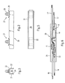
- FIG. 1 shows an oblique view of an exemplary electrical and / or electronic component 10, here in the form of a blocking circuit for a rear window antenna system.
- This component 10 comprises two Coils 11 around the radio frequency used for radio reception from the heating field the rear window is decoupled from the heating direct current. Each coil 11 is wound around a ferrite core 12.
- As another electrical and / or electronic components are a tantalum capacitor 13 and an electrolytic capacitor 14 is present. These capacitors 13, 14 serve on the one hand to suppress interference from the Vehicle electrical system and on the other hand to create a defined HF mass. These components are only contacted via crimp connections 15.
- This component 10 has two electrical Supply lines 16 and two electrical leads 17. Each supply and Discharge includes an electrical conductor 18, which is by means of a cable jacket 19 is electrically insulated.
- the component 10 inserted into a prefabricated housing part 20 is shown schematically in Figures 2, 3 and 5.
- this housing part 20 is a rail with a U-shaped cross section with the two legs 21 and 22 over a web or back 23 are connected.
- the inside of the legs 21, 22 can be provided with projections 24 to form fit with the to be introduced To produce hot melt molding compound.
- the Web 23 and the legs 21 and 22 have a cavity 26 in which the Component 10 can be inserted.
- each locking lug 27 protruding, integrally molded and elastically deflectable latching wing 28 and 29 on.
- the locking nose wings 28 are used to engage in a Locking hole on a - not shown - substrate on which the Housing part 20 is to be fixed with the aid of the locking lugs 27.
- the comparatively large latching nose wings 29 are used for resilient Support of the housing part 20 on this substrate.
- the housing part 20 is typically produced by injection molding.
- a practical embodiment is a straight, elongated, U-shaped rail with a length of approximately 90 mm, a height of approximately 11 mm, a width of approximately 14 mm and with straight, flat wall sections which have a wall thickness of approximately 1 , 0 to 1.5 mm.
- the latches 27 typically have a height of 10 mm.
- the selection of the material is determined in addition to the basically required stability, durability, impact resistance, dimensional stability and temperature resistance, above all by the elastic properties of the locking lugs. For these, a high yield stress, bending stress, bending strength, a high modulus of elasticity (on tensile stress) and high fatigue strength are required.
- thermoplastic molding materials that have a tensile strength (according to DIN 53455) greater than 42 N / mm 2 and an elastic modulus (according to DIN 53457) greater than 960 N / mm 2 have.
- the housing part 20 described above with the two integrally molded locking lugs 27 consists in particular of HOSTAFORM C 9021.
- Figure 6 shows an arrangement in which the component 10 in the open cavity 26 of the housing part 20 is inserted.
- the supply lines 16 and the leads 17 each project over the end faces of the housing part 20 also.
- FIG. 4 shows a modified embodiment in a sectional view of the housing part 20.
- the webs 21 on each inner surface and 22 integrally formed in each case an easily inwardly deflectable strip 25.
- these strips 25 are easily deflected, however, then hold component 10 within the cavity 26 in the desired arrangement.
- the molten Hotmelt molding compound is typically made from an appropriate Supply with a temperature of about 200 to 210 ° C and below a pressure of preferably 5 to 10 bar into the molding tool introduced. Rapid cooling takes place inside the molding tool, so that the still molten hot melt molding compound Components 11 and 14 contacted at a temperature of about 130 ° C.
- the solidified Hotmelt molding compound is identified by the reference symbol "30".
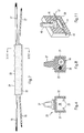
- the Figure 8 shows a schematic sectional view of this product.
- FIG. 10 shows an alternative product according to the invention.
- a blocking circuit 10 is embedded in a molded body made of solid, thermoplastic synthetic resin 30, which has been obtained from a polyamide-based hot melt molding compound that can be processed under low pressure conditions.
- Two latching noses 27 protrude from the top of the molded body and are made of another thermoplastic molding material that has a tensile strength (according to DIN 53455) greater than 42 N / mm 2 and an elastic modulus (according to DIN 53457) greater than 960 N / mm 2 having.
- Each locking lug 27 is provided with an integrally formed anchoring element 32, here with a foot 36, which is provided with an end-molded plate 37, which in turn is embedded in the molded body made of synthetic resin 30.
- FIG. 11 shows another in a schematic oblique view product according to the invention.
- the finished Product consists of a cuboid shaped body 31 made of solid Hotmelt molding compound 30 in which an electrolytic capacitor 14 of axial Design with an axial length greater than or equal to 15 mm completely embedded is.
- One feed line 16 each to the electrolytic capacitor 14 and a lead 17 from the electrolytic capacitor 14 lead from the molded body 31 out.
- a cylindrical fastener serves as a protruding fastener Rod 40, at one end in one piece a large-area disc 41 is arranged, which is embedded in the solid hotmelt molding compound and serves as an anchoring element for the fastener.
- the rod 40 and the disk 41 consist of the molding material described above high strength and high elasticity.
Landscapes
- Engineering & Computer Science (AREA)
- Microelectronics & Electronic Packaging (AREA)
- Manufacturing & Machinery (AREA)
- Mechanical Engineering (AREA)
- Injection Moulding Of Plastics Or The Like (AREA)
- Encapsulation Of And Coatings For Semiconductor Or Solid State Devices (AREA)
- Casting Or Compression Moulding Of Plastics Or The Like (AREA)
- Structures Or Materials For Encapsulating Or Coating Semiconductor Devices Or Solid State Devices (AREA)
Priority Applications (1)
| Application Number | Priority Date | Filing Date | Title |
|---|---|---|---|
| SI200130019T SI1123792T1 (en) | 2000-02-11 | 2001-02-09 | Electric and/or electronic component encapsulated by an overmoulding shaped by injection and method for producing |
Applications Claiming Priority (4)
| Application Number | Priority Date | Filing Date | Title |
|---|---|---|---|
| DE20002435U | 2000-02-11 | ||
| DE10006211 | 2000-02-11 | ||
| DE20002435U DE20002435U1 (de) | 2000-02-11 | 2000-02-11 | Formgebend umspritzte, elektrische und/oder elektronische Komponente |
| DE2000106211 DE10006211C2 (de) | 2000-02-11 | 2000-02-11 | Formgebend umspritzte, elektrische und/oder elektronische Komponente und Verfahren zur Herstellung |
Publications (2)
| Publication Number | Publication Date |
|---|---|
| EP1123792A1 true EP1123792A1 (fr) | 2001-08-16 |
| EP1123792B1 EP1123792B1 (fr) | 2003-05-14 |
Family
ID=26004307
Family Applications (1)
| Application Number | Title | Priority Date | Filing Date |
|---|---|---|---|
| EP01103121A Expired - Lifetime EP1123792B1 (fr) | 2000-02-11 | 2001-02-09 | Composant électrique et/ou électronique enrobé d'un surmoulage formé par injection et procédé de fabrication |
Country Status (3)
| Country | Link |
|---|---|
| EP (1) | EP1123792B1 (fr) |
| AT (1) | ATE240195T1 (fr) |
| DE (1) | DE50100231D1 (fr) |
Cited By (3)
| Publication number | Priority date | Publication date | Assignee | Title |
|---|---|---|---|---|
| US8643492B2 (en) | 2009-04-08 | 2014-02-04 | Sabic Innovative Plastics Ip B.V. | Encapsulated RFID tags and methods of making same |
| WO2020112366A1 (fr) * | 2018-11-30 | 2020-06-04 | Snap Inc. | Article moulé à basse pression et son procédé de fabrication |
| US11464118B2 (en) | 2019-07-25 | 2022-10-04 | PCI Private Limited | Method for manufacturing electronic device |
Citations (4)
| Publication number | Priority date | Publication date | Assignee | Title |
|---|---|---|---|---|
| DE8232239U1 (de) * | 1982-11-18 | 1983-05-11 | Standard Elektrik Lorenz Ag, 7000 Stuttgart | Gehäuse aus elastischem Kunststoff mit einem darin angeordneten elektrischen Bauelement |
| DE8232238U1 (de) * | 1982-11-18 | 1983-05-11 | Standard Elektrik Lorenz Ag, 7000 Stuttgart | Gehäuse aus elastischem Kunststoff mit einem darin angeordneten elektrischen Bauelement |
| DE19528731A1 (de) * | 1995-08-04 | 1997-02-06 | Hirschmann Richard Gmbh Co | Verfahren zum Schützen von Bauteilen sowie Schutzeinrichtungen für Bauteile |
| DE19900632A1 (de) * | 1999-01-11 | 2000-07-13 | Tyco Electronics Logistics Ag | Verfahren zur Herstellung von Gegenständen aus Schmelzklebstoff und hitzebeständiger Gegenstand |
-
2001
- 2001-02-09 AT AT01103121T patent/ATE240195T1/de active
- 2001-02-09 EP EP01103121A patent/EP1123792B1/fr not_active Expired - Lifetime
- 2001-02-09 DE DE50100231T patent/DE50100231D1/de not_active Expired - Lifetime
Patent Citations (4)
| Publication number | Priority date | Publication date | Assignee | Title |
|---|---|---|---|---|
| DE8232239U1 (de) * | 1982-11-18 | 1983-05-11 | Standard Elektrik Lorenz Ag, 7000 Stuttgart | Gehäuse aus elastischem Kunststoff mit einem darin angeordneten elektrischen Bauelement |
| DE8232238U1 (de) * | 1982-11-18 | 1983-05-11 | Standard Elektrik Lorenz Ag, 7000 Stuttgart | Gehäuse aus elastischem Kunststoff mit einem darin angeordneten elektrischen Bauelement |
| DE19528731A1 (de) * | 1995-08-04 | 1997-02-06 | Hirschmann Richard Gmbh Co | Verfahren zum Schützen von Bauteilen sowie Schutzeinrichtungen für Bauteile |
| DE19900632A1 (de) * | 1999-01-11 | 2000-07-13 | Tyco Electronics Logistics Ag | Verfahren zur Herstellung von Gegenständen aus Schmelzklebstoff und hitzebeständiger Gegenstand |
Cited By (8)
| Publication number | Priority date | Publication date | Assignee | Title |
|---|---|---|---|---|
| US8643492B2 (en) | 2009-04-08 | 2014-02-04 | Sabic Innovative Plastics Ip B.V. | Encapsulated RFID tags and methods of making same |
| WO2020112366A1 (fr) * | 2018-11-30 | 2020-06-04 | Snap Inc. | Article moulé à basse pression et son procédé de fabrication |
| US20200174259A1 (en) * | 2018-11-30 | 2020-06-04 | Stephen Andrew Steger | Low pressure molded article and method for making same |
| US10969594B2 (en) | 2018-11-30 | 2021-04-06 | Snap Inc. | Low pressure molded article and method for making same |
| CN113165235A (zh) * | 2018-11-30 | 2021-07-23 | 美国斯耐普公司 | 低压模塑制品及其制造方法 |
| US11927760B2 (en) | 2018-11-30 | 2024-03-12 | Snap Inc. | Low pressure molded article and method for making same |
| US12422685B2 (en) | 2018-11-30 | 2025-09-23 | Snap Inc. | Low pressure molded article and method for making same |
| US11464118B2 (en) | 2019-07-25 | 2022-10-04 | PCI Private Limited | Method for manufacturing electronic device |
Also Published As
| Publication number | Publication date |
|---|---|
| EP1123792B1 (fr) | 2003-05-14 |
| DE50100231D1 (de) | 2003-06-18 |
| ATE240195T1 (de) | 2003-05-15 |
Similar Documents
| Publication | Publication Date | Title |
|---|---|---|
| EP1751381B1 (fr) | Poignee de porte de vehicule automobile | |
| EP2235552B1 (fr) | Procédé et dispositif de fabrication d'un capteur de champ magnétique | |
| EP1715985B1 (fr) | Rasoir et procede de fabrication d'un tel rasoir | |
| EP0960038B1 (fr) | Mode de fabrication d'un harnais de cables | |
| DE102004044614B4 (de) | Verfahren zur Herstellung von mehrfach umspritzten Elektronikbauteilen | |
| DE4143671C2 (de) | Verfahren zur Fertigung eines Temperaturschalters | |
| DE102011087328A1 (de) | Verfahren zur Herstellung einer umspritzten Sensorbaugruppe | |
| AT411639B (de) | Verfahren zum herstellen einer kunststoffumspritzten leiterstruktur sowie elektrische schaltungseinheit mit einer kunststoffumspritzten leiterstruktur | |
| EP0361194A2 (fr) | Procédé pour enrober des composants ou assemblages de composants électriques ou électroniques et enrobage pour des composants ou assemblages de composants électriques ou électroniques | |
| AT503044B1 (de) | Fixierelement für elektrische leiter, leiterstruktur-bauteil und verfahren zu dessen herstellung | |
| EP2637485B1 (fr) | Lecteur de carte avec une pièce d'injection en plastique comprenant une structure à pistes conductrices, feuille composite, procédé de fabrication d'une structure à pistes conductrices | |
| DE3526171A1 (de) | Verfahren zur herstellung eines formlings, z.b. eines zierteils | |
| EP1170110A1 (fr) | Procédé pour fabriquer une structure conductrice surmoulée en matière plastique d'une unité de circuit électrique ainsi qu'une unité de circuit électrique comprenant une structure conductrice surmoulée en matière plastique | |
| EP1123792B1 (fr) | Composant électrique et/ou électronique enrobé d'un surmoulage formé par injection et procédé de fabrication | |
| DE10006211C2 (de) | Formgebend umspritzte, elektrische und/oder elektronische Komponente und Verfahren zur Herstellung | |
| EP3412505B1 (fr) | Procédé de fabrication d'un élément structurel d'éclairage comprenant une entretoise, élément structurel d'éclairage ainsi fabriqué et phare de véhicule équipé d'un tel élément structurel d'éclairage | |
| DE10212768A1 (de) | Im Kunststoffspritzgussverfahren insbesondere aus einem harten Kunststoff gefertigtes Betätigungselement | |
| DE20002435U1 (de) | Formgebend umspritzte, elektrische und/oder elektronische Komponente | |
| EP2031356B1 (fr) | Capteur | |
| DE102012105352A1 (de) | Positionierelement | |
| EP1221601B1 (fr) | Méthode pour fabriquer un élément électrique, ainsi que ledit élément | |
| DE10350490B3 (de) | Steckverbinder, insbesondere zur Kontaktierung einer Leiterplatte | |
| EP0609942B1 (fr) | Pièces moulées en matière plastique | |
| EP1115087B1 (fr) | Méthode de fabrication d'un dispositif transpondeur | |
| DE4204627C2 (de) | Lagerachse für Sonnenblenden von Fahrzeugen und Verfahren zum Herstellen einer solchen |
Legal Events
| Date | Code | Title | Description |
|---|---|---|---|
| PUAI | Public reference made under article 153(3) epc to a published international application that has entered the european phase |
Free format text: ORIGINAL CODE: 0009012 |
|
| AK | Designated contracting states |
Kind code of ref document: A1 Designated state(s): AT BE CH CY DE DK ES FI FR GB GR IE IT LI LU MC NL PT SE TR |
|
| AX | Request for extension of the european patent |
Free format text: AL;LT;LV;MK;RO;SI |
|
| 17P | Request for examination filed |
Effective date: 20010928 |
|
| 17Q | First examination report despatched |
Effective date: 20011227 |
|
| AKX | Designation fees paid |
Free format text: AT BE CH CY DE DK ES FI FR GB GR IE IT LI LU MC NL PT SE TR |
|
| AXX | Extension fees paid |
Free format text: SI PAYMENT 20010928 |
|
| GRAG | Despatch of communication of intention to grant |
Free format text: ORIGINAL CODE: EPIDOS AGRA |
|
| RAP1 | Party data changed (applicant data changed or rights of an application transferred) |
Owner name: VIRANT, ROBERT |
|
| RIN1 | Information on inventor provided before grant (corrected) |
Inventor name: VIRANT, ROBERT |
|
| GRAG | Despatch of communication of intention to grant |
Free format text: ORIGINAL CODE: EPIDOS AGRA |
|
| GRAH | Despatch of communication of intention to grant a patent |
Free format text: ORIGINAL CODE: EPIDOS IGRA |
|
| GRAH | Despatch of communication of intention to grant a patent |
Free format text: ORIGINAL CODE: EPIDOS IGRA |
|
| GRAA | (expected) grant |
Free format text: ORIGINAL CODE: 0009210 |
|
| AK | Designated contracting states |
Designated state(s): AT BE CH CY DE DK ES FI FR GB GR IE IT LI LU MC NL PT SE TR |
|
| AX | Request for extension of the european patent |
Extension state: SI |
|
| PG25 | Lapsed in a contracting state [announced via postgrant information from national office to epo] |
Ref country code: IT Free format text: LAPSE BECAUSE OF FAILURE TO SUBMIT A TRANSLATION OF THE DESCRIPTION OR TO PAY THE FEE WITHIN THE PRESCRIBED TIME-LIMIT;WARNING: LAPSES OF ITALIAN PATENTS WITH EFFECTIVE DATE BEFORE 2007 MAY HAVE OCCURRED AT ANY TIME BEFORE 2007. THE CORRECT EFFECTIVE DATE MAY BE DIFFERENT FROM THE ONE RECORDED. Effective date: 20030514 Ref country code: CY Free format text: LAPSE BECAUSE OF FAILURE TO SUBMIT A TRANSLATION OF THE DESCRIPTION OR TO PAY THE FEE WITHIN THE PRESCRIBED TIME-LIMIT Effective date: 20030514 Ref country code: NL Free format text: LAPSE BECAUSE OF FAILURE TO SUBMIT A TRANSLATION OF THE DESCRIPTION OR TO PAY THE FEE WITHIN THE PRESCRIBED TIME-LIMIT Effective date: 20030514 Ref country code: TR Free format text: LAPSE BECAUSE OF FAILURE TO SUBMIT A TRANSLATION OF THE DESCRIPTION OR TO PAY THE FEE WITHIN THE PRESCRIBED TIME-LIMIT Effective date: 20030514 Ref country code: FI Free format text: LAPSE BECAUSE OF FAILURE TO SUBMIT A TRANSLATION OF THE DESCRIPTION OR TO PAY THE FEE WITHIN THE PRESCRIBED TIME-LIMIT Effective date: 20030514 Ref country code: IE Free format text: LAPSE BECAUSE OF NON-PAYMENT OF DUE FEES Effective date: 20030514 |
|
| REG | Reference to a national code |
Ref country code: GB Ref legal event code: FG4D Free format text: NOT ENGLISH |
|
| REG | Reference to a national code |
Ref country code: CH Ref legal event code: EP |
|
| REG | Reference to a national code |
Ref country code: IE Ref legal event code: FG4D Free format text: GERMAN |
|
| REF | Corresponds to: |
Ref document number: 50100231 Country of ref document: DE Date of ref document: 20030618 Kind code of ref document: P |
|
| PG25 | Lapsed in a contracting state [announced via postgrant information from national office to epo] |
Ref country code: PT Free format text: LAPSE BECAUSE OF FAILURE TO SUBMIT A TRANSLATION OF THE DESCRIPTION OR TO PAY THE FEE WITHIN THE PRESCRIBED TIME-LIMIT Effective date: 20030814 Ref country code: SE Free format text: LAPSE BECAUSE OF FAILURE TO SUBMIT A TRANSLATION OF THE DESCRIPTION OR TO PAY THE FEE WITHIN THE PRESCRIBED TIME-LIMIT Effective date: 20030814 Ref country code: GR Free format text: LAPSE BECAUSE OF FAILURE TO SUBMIT A TRANSLATION OF THE DESCRIPTION OR TO PAY THE FEE WITHIN THE PRESCRIBED TIME-LIMIT Effective date: 20030814 Ref country code: DK Free format text: LAPSE BECAUSE OF FAILURE TO SUBMIT A TRANSLATION OF THE DESCRIPTION OR TO PAY THE FEE WITHIN THE PRESCRIBED TIME-LIMIT Effective date: 20030814 |
|
| REG | Reference to a national code |
Ref country code: CH Ref legal event code: NV Representative=s name: LUCHS & PARTNER PATENTANWAELTE |
|
| PG25 | Lapsed in a contracting state [announced via postgrant information from national office to epo] |
Ref country code: ES Free format text: LAPSE BECAUSE OF FAILURE TO SUBMIT A TRANSLATION OF THE DESCRIPTION OR TO PAY THE FEE WITHIN THE PRESCRIBED TIME-LIMIT Effective date: 20030825 |
|
| GBT | Gb: translation of ep patent filed (gb section 77(6)(a)/1977) | ||
| NLV1 | Nl: lapsed or annulled due to failure to fulfill the requirements of art. 29p and 29m of the patents act | ||
| REG | Reference to a national code |
Ref country code: IE Ref legal event code: FD4D Ref document number: 1123792E Country of ref document: IE |
|
| PG25 | Lapsed in a contracting state [announced via postgrant information from national office to epo] |
Ref country code: LU Free format text: LAPSE BECAUSE OF NON-PAYMENT OF DUE FEES Effective date: 20040209 |
|
| PG25 | Lapsed in a contracting state [announced via postgrant information from national office to epo] |
Ref country code: MC Free format text: LAPSE BECAUSE OF NON-PAYMENT OF DUE FEES Effective date: 20040228 Ref country code: BE Free format text: LAPSE BECAUSE OF NON-PAYMENT OF DUE FEES Effective date: 20040228 |
|
| PLBE | No opposition filed within time limit |
Free format text: ORIGINAL CODE: 0009261 |
|
| STAA | Information on the status of an ep patent application or granted ep patent |
Free format text: STATUS: NO OPPOSITION FILED WITHIN TIME LIMIT |
|
| ET | Fr: translation filed | ||
| 26N | No opposition filed |
Effective date: 20040217 |
|
| BERE | Be: lapsed |
Owner name: *VIRANT ROBERT Effective date: 20040228 |
|
| REG | Reference to a national code |
Ref country code: SI Ref legal event code: IF |
|
| REG | Reference to a national code |
Ref country code: DE Ref legal event code: R082 Ref document number: 50100231 Country of ref document: DE Representative=s name: PATENTANWAELTE WEICKMANN & WEICKMANN, DE Ref country code: DE Ref legal event code: R082 Ref document number: 50100231 Country of ref document: DE Representative=s name: WEICKMANN & WEICKMANN PATENTANWAELTE - RECHTSA, DE Ref country code: DE Ref legal event code: R082 Ref document number: 50100231 Country of ref document: DE Representative=s name: WEICKMANN & WEICKMANN PATENT- UND RECHTSANWAEL, DE |
|
| REG | Reference to a national code |
Ref country code: FR Ref legal event code: PLFP Year of fee payment: 16 |
|
| REG | Reference to a national code |
Ref country code: FR Ref legal event code: PLFP Year of fee payment: 17 |
|
| REG | Reference to a national code |
Ref country code: FR Ref legal event code: PLFP Year of fee payment: 18 |
|
| PGFP | Annual fee paid to national office [announced via postgrant information from national office to epo] |
Ref country code: GB Payment date: 20200225 Year of fee payment: 20 Ref country code: DE Payment date: 20200225 Year of fee payment: 20 Ref country code: AT Payment date: 20200218 Year of fee payment: 20 |
|
| PGFP | Annual fee paid to national office [announced via postgrant information from national office to epo] |
Ref country code: CH Payment date: 20200224 Year of fee payment: 20 |
|
| PGFP | Annual fee paid to national office [announced via postgrant information from national office to epo] |
Ref country code: FR Payment date: 20200220 Year of fee payment: 20 |
|
| REG | Reference to a national code |
Ref country code: DE Ref legal event code: R071 Ref document number: 50100231 Country of ref document: DE |
|
| REG | Reference to a national code |
Ref country code: CH Ref legal event code: PL |
|
| REG | Reference to a national code |
Ref country code: GB Ref legal event code: PE20 Expiry date: 20210208 |
|
| REG | Reference to a national code |
Ref country code: AT Ref legal event code: MK07 Ref document number: 240195 Country of ref document: AT Kind code of ref document: T Effective date: 20210209 |
|
| PG25 | Lapsed in a contracting state [announced via postgrant information from national office to epo] |
Ref country code: GB Free format text: LAPSE BECAUSE OF EXPIRATION OF PROTECTION Effective date: 20210208 |