EP1123825B9 - Store à enrouleur pour fenêtre arrière - Google Patents
Store à enrouleur pour fenêtre arrière Download PDFInfo
- Publication number
- EP1123825B9 EP1123825B9 EP01103017A EP01103017A EP1123825B9 EP 1123825 B9 EP1123825 B9 EP 1123825B9 EP 01103017 A EP01103017 A EP 01103017A EP 01103017 A EP01103017 A EP 01103017A EP 1123825 B9 EP1123825 B9 EP 1123825B9
- Authority
- EP
- European Patent Office
- Prior art keywords
- roller blind
- rear window
- edge
- winding shaft
- blind according
- Prior art date
- Legal status (The legal status is an assumption and is not a legal conclusion. Google has not performed a legal analysis and makes no representation as to the accuracy of the status listed.)
- Expired - Lifetime
Links
- 238000004804 winding Methods 0.000 claims description 45
- 230000002787 reinforcement Effects 0.000 claims 4
- 230000033001 locomotion Effects 0.000 description 4
- 230000003014 reinforcing effect Effects 0.000 description 4
- 230000005540 biological transmission Effects 0.000 description 3
- 230000000694 effects Effects 0.000 description 2
- 239000004033 plastic Substances 0.000 description 2
- 238000005452 bending Methods 0.000 description 1
- 230000037237 body shape Effects 0.000 description 1
- 230000006835 compression Effects 0.000 description 1
- 238000007906 compression Methods 0.000 description 1
- 238000010276 construction Methods 0.000 description 1
- 230000001419 dependent effect Effects 0.000 description 1
- 238000011161 development Methods 0.000 description 1
- 230000018109 developmental process Effects 0.000 description 1
- 230000003993 interaction Effects 0.000 description 1
- 239000002184 metal Substances 0.000 description 1
- 238000012544 monitoring process Methods 0.000 description 1
- 230000010355 oscillation Effects 0.000 description 1
- 230000002093 peripheral effect Effects 0.000 description 1
- 239000002985 plastic film Substances 0.000 description 1
- 229920006255 plastic film Polymers 0.000 description 1
Images


Classifications
-
- B—PERFORMING OPERATIONS; TRANSPORTING
- B60—VEHICLES IN GENERAL
- B60J—WINDOWS, WINDSCREENS, NON-FIXED ROOFS, DOORS, OR SIMILAR DEVICES FOR VEHICLES; REMOVABLE EXTERNAL PROTECTIVE COVERINGS SPECIALLY ADAPTED FOR VEHICLES
- B60J3/00—Antiglare equipment associated with windows or windscreens; Sun visors for vehicles
-
- B—PERFORMING OPERATIONS; TRANSPORTING
- B60—VEHICLES IN GENERAL
- B60J—WINDOWS, WINDSCREENS, NON-FIXED ROOFS, DOORS, OR SIMILAR DEVICES FOR VEHICLES; REMOVABLE EXTERNAL PROTECTIVE COVERINGS SPECIALLY ADAPTED FOR VEHICLES
- B60J1/00—Windows; Windscreens; Accessories therefor
- B60J1/20—Accessories, e.g. wind deflectors, blinds
- B60J1/2011—Blinds; curtains or screens reducing heat or light intensity
- B60J1/2013—Roller blinds
- B60J1/2036—Roller blinds characterised by structural elements
- B60J1/2052—Guides
-
- B—PERFORMING OPERATIONS; TRANSPORTING
- B60—VEHICLES IN GENERAL
- B60J—WINDOWS, WINDSCREENS, NON-FIXED ROOFS, DOORS, OR SIMILAR DEVICES FOR VEHICLES; REMOVABLE EXTERNAL PROTECTIVE COVERINGS SPECIALLY ADAPTED FOR VEHICLES
- B60J1/00—Windows; Windscreens; Accessories therefor
- B60J1/20—Accessories, e.g. wind deflectors, blinds
- B60J1/2011—Blinds; curtains or screens reducing heat or light intensity
- B60J1/2013—Roller blinds
- B60J1/2019—Roller blinds powered, e.g. by electric, hydraulic or pneumatic actuators
- B60J1/2027—Roller blinds powered, e.g. by electric, hydraulic or pneumatic actuators with a buckle-proof guided flexible actuating element acting on the draw bar for pushing or push-pulling, e.g. a Bowden cable
-
- B—PERFORMING OPERATIONS; TRANSPORTING
- B60—VEHICLES IN GENERAL
- B60J—WINDOWS, WINDSCREENS, NON-FIXED ROOFS, DOORS, OR SIMILAR DEVICES FOR VEHICLES; REMOVABLE EXTERNAL PROTECTIVE COVERINGS SPECIALLY ADAPTED FOR VEHICLES
- B60J1/00—Windows; Windscreens; Accessories therefor
- B60J1/20—Accessories, e.g. wind deflectors, blinds
- B60J1/2011—Blinds; curtains or screens reducing heat or light intensity
- B60J1/2013—Roller blinds
- B60J1/2036—Roller blinds characterised by structural elements
- B60J1/2044—Draw bars, including elements attached to it, e.g. sliding shoes, gripping elements or pull cords
-
- B—PERFORMING OPERATIONS; TRANSPORTING
- B60—VEHICLES IN GENERAL
- B60J—WINDOWS, WINDSCREENS, NON-FIXED ROOFS, DOORS, OR SIMILAR DEVICES FOR VEHICLES; REMOVABLE EXTERNAL PROTECTIVE COVERINGS SPECIALLY ADAPTED FOR VEHICLES
- B60J1/00—Windows; Windscreens; Accessories therefor
- B60J1/20—Accessories, e.g. wind deflectors, blinds
- B60J1/2011—Blinds; curtains or screens reducing heat or light intensity
- B60J1/2013—Roller blinds
- B60J1/2066—Arrangement of blinds in vehicles
- B60J1/2072—Blinds with inclined or vertical orientation of the winding axis
-
- B—PERFORMING OPERATIONS; TRANSPORTING
- B60—VEHICLES IN GENERAL
- B60J—WINDOWS, WINDSCREENS, NON-FIXED ROOFS, DOORS, OR SIMILAR DEVICES FOR VEHICLES; REMOVABLE EXTERNAL PROTECTIVE COVERINGS SPECIALLY ADAPTED FOR VEHICLES
- B60J1/00—Windows; Windscreens; Accessories therefor
- B60J1/20—Accessories, e.g. wind deflectors, blinds
- B60J1/2011—Blinds; curtains or screens reducing heat or light intensity
- B60J1/2013—Roller blinds
- B60J1/2066—Arrangement of blinds in vehicles
- B60J1/2075—Arrangement of blinds in vehicles specially adapted for fixed windows
- B60J1/208—Arrangement of blinds in vehicles specially adapted for fixed windows for rear windows
Definitions
- the well-known rear window blind has a Base on, in which a winding shaft rotatably mounted is.
- the winding shaft is with the help of a spring motor in Winding direction of a roller blind biased at the Winding shaft is attached with an edge.
- the other edge is connected to a drawbar, at the two-armed Attack levers that are mounted on the base.
- the bearing axes The lever is perpendicular to the winding shaft.
- the well-known rear window blind is not suitable for the rear window of estate cars and similar motor vehicles with large tailgate.
- DE 36 08 927 A1 shows another form of rear window blinds.
- the rear window blind again has one Winding on, attached to the edge of a roller blind is.
- the other edge of the blind is with a Extensible profile or bow provided, the end in guide rails is guided.
- the winding shaft is using an electric motor in the sense of winding or unwinding the Roller blind set in motion.
- each end of the statement profile respectively a tension spring immediately.
- the tension spring runs in the Guide rail to the remote from the winding shaft The End. At this end there is a diverter, through which passes through the tension spring to continue in the course to lie parallel to the guide rail.
- the roller blind In the rear window blind according to the invention is a rotatably mounted winding shaft provided at the with a Edge portion of the blank of the roller blind is attached. At one of this section other remote section the roller blind engages an actuator to the roller blind remove from the winding shaft and in the clamped To maintain state. For retracting and extending the roller blind Power-operated drive means are used.
- the electric motor interacts with the winding shaft, while the tension spring at the other end of the roller blind attack.
- the electric motor with the winding shaft immediately Is connected by gearing, that part is the Roller blind, which travels the longest way, over a rope connected with a tension spring.
- the new construction allows the rear window blind largely disappear below the parcel shelf to let when the roller blind used in a station wagon becomes. When retracted, it is then practically complete withdrawn behind the outlines of the window.
- the winding shaft can, depending on the space and the special body shape vertically, for example in the C-pillar, in the tailgate profile near the C-pillar a car or parallel to the lower edge of the rear window be arranged.
- the attachment of the winding shaft laterally next to the Window frame edge also allows the winding shaft in that area of the flap, where they not collided with the windscreen wiper motor.
- roller blind A very stable guidance of the roller blind results, when the roller blind is guided between two guide rails will, starting from the winding shaft approximately in the same Direction. Because these guide rails because of the Rear window geometry not parallel to each other, the roller blind contains at least one bow that is adjustable in length is. He adapts to itsätig himself changing distance between the guide rails.
- the drive means of the rear roller blind includes at least one electric motor as well as spring means. Between the electric motor and the Federstoffn is kinematically the roller blind, the Drive motor, the position of the top or side edge of the Roller blind defined while the spring means as "slave drive” provide for the tension in the roller blind.
- Fig. 1 is schematized by dotted lines the rear end of a motor vehicle 1 with a left and a right C-pillar indicated. Between the C-pillars 2, rear window 3 extends from a lower edge 4 to a roof trailing edge 5. In front of the rear window 3 there is a hat rack 6 with a across the width continuous slot 7. Furthermore, inside the Motor vehicle 1 to recognize a window shade 8, the in Fig. 1 is shown in the extended position.
- a winding shaft 9 which is below the parcel shelf 6 is rotatably mounted, and a roller blind 11th
- the parcel shelf 6 For storage of the winding shaft 9 are at the bottom the parcel shelf 6 next to the slot 7 two bearing blocks 12 and 13 receive the journals 14 and 15, axially from the protrude tubular winding shaft 9.
- a schematically shown spring motor 16 which is firmly connected at 17 with the winding shaft 9 and the other end rotatably coupled to the bearing pin 15 is.
- the bearing pin 15 in turn sits non-rotatably in the Bearing 13.
- the spring motor 16 forms part of the drive device the rear window roller blind 8 and generates a Biasing force in the sense of winding up the roller blind 11 on the winding shaft 9.
- the roller blind 11 at the Winding shaft 9 for example by means of a welt in a known Way attached.
- the roller blind 11 consists of a trapezoidal Cut from a plastic film, the sufficient Sunlight shields.
- the roller blind 11 is of a left and a right Side edge 18, 19 and an upper edge 21 and a attached to the winding shaft 9, not recognizable Edge, limited.
- At the upper edge 21 is an example of a plastic profile existing edge reinforcing strip 22nd attached, from the left to the right side edge 12, 13 is enough.
- To the rear window roller 8 also includes a single Guide rail 23, coming from the roller blind slot 7 to extends to the roof trailing edge 5 and is fixed there; she runs next to the right C-pillar 2 to this approximately parallel.
- a second guide rail is in this embodiment unavailable.
- the Guide rail 23 consists of a C-shaped profile with a behind-grip guide 24.
- the guide 24 opens at a slot 25 in the direction of the roller blind 11th
- a carriage 26 runs, consisting from a cross-section to the interior of the guide groove 24 attached body 27, of which a strip-shaped Flange 28 goes out through the slot 25th protrudes outwards.
- the main body 27 is substantially cylindrical and the interior of the guide groove 24 of the guide rail 23 also cylindrical.
- a boom 29 is attached, the protrudes from the main body 27 substantially at right angles and in turn has the form of a guide rail, in the edge reinforcing strip 22 longitudinally displaceable is included.
- the boom 29 is designed in such a way that the edge reinforcing strip 22 only one Degree of freedom, namely in the direction parallel to the longitudinal extent of the jib 29. In the direction perpendicular thereto is she tied up in the jib 29?
- the actuator 32 is from a pressure-stiff, linear element, for example a flexible metal or plastic wire 33, the soul of a Bowden cable or a shear-stiffened, stranded strand of wire formed.
- a pressure-stiff, linear element for example a flexible metal or plastic wire 33, the soul of a Bowden cable or a shear-stiffened, stranded strand of wire formed.
- At least on the engine side End carries the actuator 32 on his Outer peripheral surface of a screw or worm 34 forming Wire winding 35 the immovable with the actuator 32 is connected.
- Actuators of this type are also available under the trade name "SU-flexwelle" and are used among other things in window regulators.
- the drive motor 31 is a permanently energized DC motor, which is followed by a reduction gear 36 is.
- a spur gear 38 On an output shaft 37 of the transmission 36th rotatably sits a spur gear 38 whose pitch with the Division of the screw or screw 34 matches.
- a guide 39 which is designed such that they tangentially the screw 34 of the actuator 32 leads to the output gear 38 and forces the Teeth of the spur gear 38 form-fitting between the turns the screw 34 can engage.
- the actuator 32 connects the spur gear 38 geared to the carriage 26, and that is it starting from the transmission 36 and there existing guide 39th pressure-resistant in a shell 33a to the lower end of the guide rail 23 led. At this point, the actuator occurs 32 in the interior of the guide groove 24 a. The free end 41 of the actuator 32 is freely abutting at the lower end of the guide carriage 26 at.
- the windows When installed, the windows are open when the rear window is open 8 to recognize only the guide rail 23.
- the guide rail 23 runs next to the right edge of the window and thus disappears largely. Only the boom 29 would be seen in the slot 7 through which the Roller blind 11 is extended upward.
- the spur gear 38 is the pressure-resistant or pressure-resistant guided actuator 32 in the direction of the guide rail 23 advances.
- this feed motion pushes the guided in the interior of the guide rail 23 Actuator 32, the guide carriage 26 together with the attached boom 29 upwards in the direction of the roof trailing edge 5. It is according to roller blind 11th unwound from the winding shaft 9 and through the roller blind slot 7 pulled out in the rear parcel shelf 6.
- the motor current increases, which in known Way of a known monitoring circuit is evaluated to be independent of the switch control to de-energize the drive motor 31 by the user.
- the arrangement also ensures, as is known, a restart of the motor current only for the reverse To allow direction of rotation.
- roller blind 11 is now fully extended and the boom 29 abuts the upper edge of the window frame 5 on. In front of the entire window surface, the roller blind 11 clamped.
- a swinging of the boom 29 can be extended Avoid rear window roller blind 8, if according to the upper end position at the top of the rear windows 3 a hook-shaped pocket 42 is attached, which is a down includes open groove 43.
- the groove 43 takes in the upper end position the boom 29 at a position that of the Carriage 26 is spaced. Oscillation of the jib 53 about the longitudinal axis of the carriage 49 are characterized excluded with certainty.
- the Electric motor 31 To retract the rear window roller blind 8 sets the user the electric motor 31 via a corresponding switch in the opposite direction of rotation in function.
- the Spur gear 38 which meshes with the screw 34, pulls the Actuator 32 down from the guide rail 23rd back, whereby the force acting against the carriage 49 feed force subsides.
- the spring motor 16 is characterized in the Position corresponding to the retraction of the actuator 32 to wind the blind sheet 11 again on the winding shaft 9.
- the lower end position of the actuator can in be queried similarly as the upper end position, and be shut down in a corresponding manner.
- roller blind 11 through the Effect of the spring motor 16 kept taut while the Position by the self-locking drive motor 31st is given.
- the spring drive 16 could also swap places with the drive motor 31, in such a way that the drive motor 31, the winding shaft 9 positively drives while the actuator 32 acted upon by a compression spring or such is replaced.
- the carriage 26 are biased in the unwinding direction, while the roller blind 11 against the action of the spring 16 the winding shaft 9 is wound.
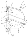
- FIG 3 is an embodiment of a tail Window shade 8 illustrates the two guide rails 23a and 23b.
- the guide rails 23a and 23b have same cross-sectional shape, as related is explained in detail with Fig. 2.
- the guide rail 23a is substantially straight according to the course the right edge of the window frame, while the guide rail 23b approximately parallel to the left rear window edge is aligned.
- a rear window roller blind for motor vehicles has a Winding shaft, which is preferably rotatable under the parcel shelf is stored. Through a slot in the parcel shelf can pulled out a roller blind, which covers the window. For this purpose, at the edge of the roller blind, the furthest way back, an actuator on.
- the actuator is a linear element that ever after execution either tensile strength or pressure resistant.
- the Roller blind itself can be next to the window with the help of at least a guide rail or one or two pressure or rigid actuators are kept clamped.
Landscapes
- Engineering & Computer Science (AREA)
- Mechanical Engineering (AREA)
- Operating, Guiding And Securing Of Roll- Type Closing Members (AREA)
Claims (18)
- Store à enrouleur (8) pour lunettes arrière de véhicules automobiles, qui est délimité par un bord de cadre de vitre (4) inférieur, sensiblement horizontal, ainsi que par deux bords de cadre de vitre (2) latéraux, sensiblement verticaux, et un bord de cadre de vitre (5) supérieur, sensiblement horizontal, comprenant
une barre d'enroulement (9) montée tournante,
une bande (11) de store à enrouleur, dont le panneau, au moins dans une portion de sa longueur, correspond au moins approximativement à la forme de la lunette arrière (3) et qui présente un bord périphérique de bande de store à enrouleur, lequel bord forme une portion fixée à la barre d'enroulement (9), ainsi qu'une portion (21) éloignée de la barre d'enroulement (9), caractérisé en ce que le store pour lunette arrière présente
au moins un câble (32), qui est relié à la portion (21) de store à enrouleur éloignée de la barre d'enroulement (9), et
des moyens d'entraínement (16,31) pour opérer l'enroulement et le déroulement motorisés de la bande de store,
les moyens d'entraínement (16,31) englobant un ressort de traction, qui est relié via le câble (32) à la bande de store (11) et met ladite bande de store (11) sous précontrainte, dans le sens du déroulement de la barre d'enroulement (9), et au moins un moto-réducteur (31) qui est couplé à la barre d'enroulement (9). - Store à enrouleur pour lunettes arrière selon la revendication 1, caractérisé en ce que la barre d'enroulement (9) est disposée à peu près latéralement à côté de la lunette arrière (3).
- Store selon la revendication 1, caractérisé en ce que la barre d'enroulement (9) est disposée à peu près horizontalement, en-dessous de la lunette arrière (3).
- Store selon la revendication 1, caractérisé en ce qu'il est prévu au moins un rail de guidage (23).
- Store selon la revendication 1, caractérisé en ce qu'il est prévu deux rails de guidage (23a, 23b).
- Store selon la revendication 5, caractérisé en ce que le rail de guidage (23), au nombre d'au moins un, est disposé horizontalement.
- Store selon la revendication 5, caractérisé en ce que le rail de guidage (23), au nombre d'au moins un, est parallèle au bord de cadre de vitre (4) inférieur.
- Store selon la revendication 5, caractérisé en ce que le rail de guidage (23), au nombre d'au moins un, est disposé latéralement à côté de la lunette arriére (3).
- Store selon la revendication 5, caractérisé en ce que le rail de guidage (23), au nombre d'au moins un, s'étend parallèlement au bord de cadre de vitre (2)latéral.
- Store selon la revendication 1, caractérisé en ce que le bord de la bande de store présente un élément de renfort de bord (22, 52), au moins dans une portion (21) éloignée de la barre d'enroulement (9).
- Store selon la revendication 10, caractérisé en ce que l'élément de renfort de bord (22) est flexible.
- Store selon la revendication 10, caractérisé en ce qu'une portion de l'élément de renfort de bord (22) est rigide.
- Store selon la revendication 10, caractérisé en ce qu'au moins une portion de l'élément de renfort de bord (22) sert de barre de traction.
- Store selon la revendication 4, caractérisé en ce que la bande de store(11) est pourvue d'au moins un arceau (52) qui est monté côté extrémité dans le rail de guidage (23), au nombre d'au moins un.
- Store selon la revendication 14, caractérisé en ce que l'arceaud (52), au nombre d'au moins un, est monté avec ses deux extrémités dans des rails de guidage (23a, 23b).
- Store selon la revendication 14, caractérisé en ce que l'arceau (52) est réglable en longueur de manière télescopique.
- Store selon la revendication 5, caractérisé en ce qu'un chariot (26) est guidé dans le rail de guidage (23), au nombre d'au moins un, auquel chariot est fixé un bras (29) auquel est liée une portion (21) du bord de la bande de store.
- Store selon la revendication 17, caractérisé en ce que la portion (21) du bord de la bande de store est liée au bras (29) avec possibilité de coulissement longitudinal.
Applications Claiming Priority (2)
| Application Number | Priority Date | Filing Date | Title |
|---|---|---|---|
| DE10005951A DE10005951A1 (de) | 2000-02-09 | 2000-02-09 | Heckfensterrollo |
| DE10005951 | 2000-02-09 |
Publications (4)
| Publication Number | Publication Date |
|---|---|
| EP1123825A2 EP1123825A2 (fr) | 2001-08-16 |
| EP1123825A3 EP1123825A3 (fr) | 2002-12-18 |
| EP1123825B1 EP1123825B1 (fr) | 2004-11-24 |
| EP1123825B9 true EP1123825B9 (fr) | 2005-06-29 |
Family
ID=7630489
Family Applications (1)
| Application Number | Title | Priority Date | Filing Date |
|---|---|---|---|
| EP01103017A Expired - Lifetime EP1123825B9 (fr) | 2000-02-09 | 2001-02-08 | Store à enrouleur pour fenêtre arrière |
Country Status (5)
| Country | Link |
|---|---|
| US (1) | US20010017194A1 (fr) |
| EP (1) | EP1123825B9 (fr) |
| JP (1) | JP2001241277A (fr) |
| KR (1) | KR20010078789A (fr) |
| DE (2) | DE10005951A1 (fr) |
Families Citing this family (41)
| Publication number | Priority date | Publication date | Assignee | Title |
|---|---|---|---|---|
| DE10005970A1 (de) * | 2000-02-09 | 2001-08-23 | Bos Gmbh | Seitenfensterrollo |
| DE10057762A1 (de) * | 2000-11-22 | 2002-06-06 | Bos Gmbh | Fensterrollo mit Ausgleich gegen Verzug |
| DE10057763C2 (de) * | 2000-11-22 | 2002-10-24 | Bos Gmbh | Doppelrollo mit vereinfachtem Antrieb |
| DE10057760B4 (de) * | 2000-11-22 | 2004-08-12 | Bos Gmbh & Co. Kg | Fensterrollo mit Zentriereinrichtung für den Zugstab |
| JP3662847B2 (ja) * | 2000-12-28 | 2005-06-22 | 松下電工株式会社 | ブラインド装置 |
| DE10113616C1 (de) * | 2001-03-20 | 2002-10-10 | Butz Peter Verwaltung | Laderaumabdeckung für Kraftwagen, wie für Kombinations-Personenkraftwagen od. dgl. |
| DE10113621C1 (de) * | 2001-03-20 | 2002-10-10 | Butz Peter Verwaltung | Laderaumabdeckung für Kraftwagen, wie für Kombinations-Personenkraftwagen od. dgl. |
| JPWO2002080172A1 (ja) * | 2001-03-30 | 2004-07-22 | ソニー株式会社 | 記録媒体の記録又は再生装置並びにデータの出力制御方法 |
| DE10151872B4 (de) * | 2001-10-24 | 2007-10-04 | Bos Gmbh & Co. Kg | Geteiltes Fensterrollo für Kraftfahrzeuge |
| FR2841185A1 (fr) * | 2002-06-25 | 2003-12-26 | Wagon Automotive Snc | Store a enrouleur a entrainement par cable, et vehicule automobile correspondant |
| DE10245901A1 (de) * | 2002-09-30 | 2004-04-08 | Schwab Technik Gmbh | Rolloanordnung für Fahrzeugscheiben |
| DE10248591B4 (de) | 2002-10-17 | 2006-04-20 | Bos Gmbh & Co. Kg | Fensterrollo mit Deckel auf dem Auszugschlitz |
| DE10256599A1 (de) * | 2002-12-04 | 2004-06-17 | Arvinmeritor Gmbh | Rollosystem, insbesondere für ein Kraftfahrzeug |
| FR2851202B1 (fr) * | 2003-02-13 | 2005-05-06 | Wagon Automotive Snc | Rail de guidage pre-equipe pour store de vehicule automobile, ensemble de store, procede d'assemblage et de montage et vehicules automobile correspondants |
| FR2851199B1 (fr) * | 2003-02-13 | 2006-10-20 | Wagon Automotive Snc | Store pour vehicule automobile a ralentisseur en fin de course, et vehicule correspondant. |
| DE10322709B3 (de) * | 2003-05-20 | 2005-03-17 | Webasto Ag | Sonnenschutzrolloanordnung für ein Fahrzeugdach sowie Fahrzeugdach mit einer solchen Sonnenschutzrolloanordnung |
| DE10334695A1 (de) * | 2003-07-25 | 2005-02-10 | Brose Fahrzeugteile Gmbh & Co. Kg | Rollo-Anordnung für ein Fenster eines Kraftfahrzeugs |
| DE10338722A1 (de) * | 2003-08-22 | 2005-03-17 | Opel Eisenach Gmbh | Beschattungssystem für eine Panoramascheibe |
| US6983786B2 (en) * | 2003-09-24 | 2006-01-10 | Ing-Wen Chen | Height-adjustable car curtain |
| DE10353778A1 (de) * | 2003-11-18 | 2005-06-23 | Bos Gmbh & Co. Kg | Fahrzeugrollo mit vereinfachter Ankoppelung der Führungsschienen |
| DE10356911B3 (de) * | 2003-12-02 | 2005-01-20 | Bos Gmbh & Co. Kg | Laderaumschutzvorrichtung für ein Kraftfahrzeug |
| DE10357028A1 (de) * | 2003-12-03 | 2005-06-30 | Volkswagen Ag | Verdunkelungseinrichtung für eine Fensterscheibe eines Fahrzeuges |
| DE102004036948B3 (de) * | 2004-07-29 | 2006-03-23 | Bos Gmbh & Co. Kg | Gekrümmtes Fensterrollo mit innen liegendem Federwiderlager |
| DE102004058296A1 (de) * | 2004-12-02 | 2006-06-08 | Bos Gmbh & Co. Kg | Rolloanordnung mit verdeckter Rastung |
| JP4560442B2 (ja) * | 2005-05-23 | 2010-10-13 | トヨタ紡織株式会社 | サンシェード開閉装置 |
| DE102005029559B4 (de) * | 2005-06-23 | 2007-05-03 | Bos Gmbh & Co. Kg | Heckfensterrollo mit vollständiger Schlitzabdeckung durch das Auszugsprofil |
| DE102005030707A1 (de) * | 2005-06-29 | 2007-01-04 | Bos Gmbh & Co. Kg | Fensterrollo für Kraftfahrzeuge mit formschlüssigem Anschlag auf dem Betätigungsglied |
| DE102005036318A1 (de) * | 2005-07-29 | 2007-02-01 | Bos Gmbh & Co. Kg | Fensterrollo mit glatten Schubgliedern |
| EP1787864B1 (fr) * | 2005-11-22 | 2009-03-25 | Mazda Motor Corporation | Structure arrière de véhicule |
| DE102006008160A1 (de) * | 2006-02-22 | 2007-08-30 | Bos Gmbh & Co. Kg | Rollo mit Zentrierung durch Anschläge |
| KR100828600B1 (ko) | 2006-08-21 | 2008-05-09 | 현대자동차주식회사 | 차량용 선바이저의 시야 확보 장치 |
| USD597912S1 (en) * | 2007-09-21 | 2009-08-11 | Honda Motor Co., Ltd. | Sunvisor |
| JP5310405B2 (ja) * | 2009-09-03 | 2013-10-09 | トヨタ紡織株式会社 | サンシェード装置 |
| JP5528790B2 (ja) * | 2009-12-28 | 2014-06-25 | 芦森工業株式会社 | 車両用ウインドウシェード装置 |
| JP5646934B2 (ja) * | 2010-09-24 | 2014-12-24 | 芦森工業株式会社 | サンシェード装置 |
| US20120186759A1 (en) * | 2011-01-25 | 2012-07-26 | Paul Lin | Sunshade Assembly for a Side Window of a Vehicle |
| DE102011006237A1 (de) * | 2011-03-28 | 2012-10-04 | Bos Gmbh & Co. Kg | Rollosystem für ein Kraftfahrzueg |
| DE102014218566A1 (de) * | 2014-08-01 | 2016-02-04 | Bos Gmbh & Co. Kg | Beschattungsvorrichtung für ein transparentes Flächenteil eines Kraftfahrzeugs |
| DE102014215153B4 (de) | 2014-08-01 | 2022-01-27 | Bos Gmbh & Co. Kg | Beschattungsvorrichtung für ein transparentes Flächenteil eines Kraftfahrzeugs |
| DE102014215150A1 (de) | 2014-08-01 | 2016-02-04 | Bos Gmbh & Co. Kg | Beschattungsvorrichtung für ein transparentes Flächenteil eines Kraftfahrzeugs |
| KR101602280B1 (ko) * | 2015-02-23 | 2016-03-11 | 크레노바멀티미디어 주식회사 | 리눅스 운영체계 기반의 디지털 셋톱박스 |
Family Cites Families (6)
| Publication number | Priority date | Publication date | Assignee | Title |
|---|---|---|---|---|
| DE3415930A1 (de) * | 1984-04-28 | 1985-10-31 | Baumeister & Ostler, 7307 Aichwald | Kraftfahrzeugfensterrollo |
| DE3608927A1 (de) * | 1986-03-18 | 1987-09-24 | Ieper Ind Nv | Blendschutzeinrichtung fuer ein fahrzeug |
| DE3612165A1 (de) | 1986-04-11 | 1987-10-22 | Baumeister & Ostler | Fuehrungsloses fensterrollo, insbesondere fuer kraftfahrzeuge |
| JPH0478628A (ja) * | 1990-05-23 | 1992-03-12 | Nhk Spring Co Ltd | シート状物巻取装置 |
| US5860466A (en) * | 1996-02-02 | 1999-01-19 | Kao; Nien Tsu Tim | Windshield shelter |
| US5752560A (en) * | 1997-03-21 | 1998-05-19 | Cherng; Bing Jye | Electric sunshield for automobiles |
-
2000
- 2000-02-09 DE DE10005951A patent/DE10005951A1/de not_active Withdrawn
-
2001
- 2001-01-26 JP JP2001018041A patent/JP2001241277A/ja active Pending
- 2001-02-08 DE DE50104571T patent/DE50104571D1/de not_active Expired - Lifetime
- 2001-02-08 KR KR1020010006083A patent/KR20010078789A/ko not_active Withdrawn
- 2001-02-08 US US09/779,765 patent/US20010017194A1/en not_active Abandoned
- 2001-02-08 EP EP01103017A patent/EP1123825B9/fr not_active Expired - Lifetime
Also Published As
| Publication number | Publication date |
|---|---|
| DE50104571D1 (de) | 2004-12-30 |
| US20010017194A1 (en) | 2001-08-30 |
| EP1123825B1 (fr) | 2004-11-24 |
| DE10005951A1 (de) | 2001-08-16 |
| EP1123825A2 (fr) | 2001-08-16 |
| KR20010078789A (ko) | 2001-08-21 |
| JP2001241277A (ja) | 2001-09-04 |
| EP1123825A3 (fr) | 2002-12-18 |
Similar Documents
| Publication | Publication Date | Title |
|---|---|---|
| EP1123825B9 (fr) | Store à enrouleur pour fenêtre arrière | |
| EP1800923B1 (fr) | Store de fenêtre latéral doté d'une barre portante | |
| EP1182066B1 (fr) | Véhicule avec store à enrouleur dans le toit | |
| EP1211109B1 (fr) | Store à enrouler avec dispositif de centrage pour la tige de tension | |
| EP1886853B1 (fr) | Store de fenêtre doté d'un actionnement par le lève-glace | |
| EP1449692B1 (fr) | Protection solaire systeme pour vehicule | |
| EP1612070B1 (fr) | Store à rouleau de fenêtre pour vitres de véhicule courbées ou non rectangulaires | |
| EP1479564B1 (fr) | dispositif de protection pour intérieur véhicule | |
| DE10020212B4 (de) | Seitenfensterrollo mit Schlitzabdeckung | |
| EP1533158B1 (fr) | Système de store à enrouleur pour vitres latérals pourvu d'un pièce de contour de vitre | |
| EP2039547B1 (fr) | Store de fenêtre latérale doté d'une aide à l'introduction | |
| DE10057764A1 (de) | Fensterrollo mit variabler Abschattungswirkung | |
| EP1375219A2 (fr) | Store à enrouleur pour lunette arrière avec boítier levant | |
| EP1209013A2 (fr) | Vitre avec store à enrouleur attaché | |
| DE102011113207B4 (de) | Fahrzeugrolloanordnung und Fahrzeugdach | |
| EP1932700A2 (fr) | Store de fenêtre triangulaire pour véhicules automobiles | |
| EP1782979A2 (fr) | Store à enrouleur sans lacune pour une lunette arrière | |
| EP3478521B1 (fr) | Dispositif d'ombrage pour une vitre de véhicule automobile | |
| DE202007015602U1 (de) | Elektrisches Seitenfensterrollo | |
| EP1739275A2 (fr) | Volet roulant avec dispositif anti-pincement éléctronique | |
| DE102012215433A1 (de) | Rollosystem für einen Fahrzeuginnenraum | |
| EP1738942A2 (fr) | Store à enrouleur pour véhicule automobile muni d'une butée de contact fixée rigidement sur un actionneur | |
| DE202007008178U1 (de) | Seitenfensterrollo | |
| DE102007011272A1 (de) | Sonnenschutzsystem für Kraftfahrzeugfenster |
Legal Events
| Date | Code | Title | Description |
|---|---|---|---|
| PUAI | Public reference made under article 153(3) epc to a published international application that has entered the european phase |
Free format text: ORIGINAL CODE: 0009012 |
|
| AK | Designated contracting states |
Kind code of ref document: A2 Designated state(s): AT BE CH CY DE DK ES FI FR GB GR IE IT LI LU MC NL PT SE TR |
|
| AX | Request for extension of the european patent |
Free format text: AL;LT;LV;MK;RO;SI |
|
| PUAL | Search report despatched |
Free format text: ORIGINAL CODE: 0009013 |
|
| AK | Designated contracting states |
Kind code of ref document: A3 Designated state(s): AT BE CH CY DE DK ES FI FR GB GR IE IT LI LU MC NL PT SE TR |
|
| AX | Request for extension of the european patent |
Free format text: AL;LT;LV;MK;RO;SI |
|
| 17P | Request for examination filed |
Effective date: 20030228 |
|
| 17Q | First examination report despatched |
Effective date: 20030429 |
|
| AKX | Designation fees paid |
Designated state(s): DE FR GB IT |
|
| GRAP | Despatch of communication of intention to grant a patent |
Free format text: ORIGINAL CODE: EPIDOSNIGR1 |
|
| GRAS | Grant fee paid |
Free format text: ORIGINAL CODE: EPIDOSNIGR3 |
|
| GRAA | (expected) grant |
Free format text: ORIGINAL CODE: 0009210 |
|
| AK | Designated contracting states |
Kind code of ref document: B1 Designated state(s): DE FR GB IT |
|
| REG | Reference to a national code |
Ref country code: GB Ref legal event code: FG4D Free format text: NOT ENGLISH |
|
| RAP2 | Party data changed (patent owner data changed or rights of a patent transferred) |
Owner name: BOS GMBH & CO. KG |
|
| REF | Corresponds to: |
Ref document number: 50104571 Country of ref document: DE Date of ref document: 20041230 Kind code of ref document: P |
|
| REG | Reference to a national code |
Ref country code: IE Ref legal event code: FG4D Free format text: GERMAN |
|
| GBT | Gb: translation of ep patent filed (gb section 77(6)(a)/1977) |
Effective date: 20050412 |
|
| REG | Reference to a national code |
Ref country code: IE Ref legal event code: FD4D |
|
| ET | Fr: translation filed | ||
| PLBE | No opposition filed within time limit |
Free format text: ORIGINAL CODE: 0009261 |
|
| STAA | Information on the status of an ep patent application or granted ep patent |
Free format text: STATUS: NO OPPOSITION FILED WITHIN TIME LIMIT |
|
| 26N | No opposition filed |
Effective date: 20050825 |
|
| PGFP | Annual fee paid to national office [announced via postgrant information from national office to epo] |
Ref country code: GB Payment date: 20080220 Year of fee payment: 8 Ref country code: IT Payment date: 20080223 Year of fee payment: 8 |
|
| GBPC | Gb: european patent ceased through non-payment of renewal fee |
Effective date: 20090208 |
|
| PG25 | Lapsed in a contracting state [announced via postgrant information from national office to epo] |
Ref country code: GB Free format text: LAPSE BECAUSE OF NON-PAYMENT OF DUE FEES Effective date: 20090208 |
|
| PG25 | Lapsed in a contracting state [announced via postgrant information from national office to epo] |
Ref country code: IT Free format text: LAPSE BECAUSE OF NON-PAYMENT OF DUE FEES Effective date: 20090208 |
|
| PGFP | Annual fee paid to national office [announced via postgrant information from national office to epo] |
Ref country code: FR Payment date: 20140219 Year of fee payment: 14 |
|
| REG | Reference to a national code |
Ref country code: FR Ref legal event code: ST Effective date: 20151030 |
|
| PG25 | Lapsed in a contracting state [announced via postgrant information from national office to epo] |
Ref country code: FR Free format text: LAPSE BECAUSE OF NON-PAYMENT OF DUE FEES Effective date: 20150302 |
|
| PGFP | Annual fee paid to national office [announced via postgrant information from national office to epo] |
Ref country code: DE Payment date: 20160226 Year of fee payment: 16 |
|
| REG | Reference to a national code |
Ref country code: DE Ref legal event code: R119 Ref document number: 50104571 Country of ref document: DE |
|
| PG25 | Lapsed in a contracting state [announced via postgrant information from national office to epo] |
Ref country code: DE Free format text: LAPSE BECAUSE OF NON-PAYMENT OF DUE FEES Effective date: 20170901 |