EP1123852A1 - Gelenkverbindung zwischen zwei gelenkig miteinander verbundenen Fahrzeugeinheiten - Google Patents
Gelenkverbindung zwischen zwei gelenkig miteinander verbundenen Fahrzeugeinheiten Download PDFInfo
- Publication number
- EP1123852A1 EP1123852A1 EP01102452A EP01102452A EP1123852A1 EP 1123852 A1 EP1123852 A1 EP 1123852A1 EP 01102452 A EP01102452 A EP 01102452A EP 01102452 A EP01102452 A EP 01102452A EP 1123852 A1 EP1123852 A1 EP 1123852A1
- Authority
- EP
- European Patent Office
- Prior art keywords
- pin
- clamping piece
- bearing shell
- articulated
- bridge
- Prior art date
- Legal status (The legal status is an assumption and is not a legal conclusion. Google has not performed a legal analysis and makes no representation as to the accuracy of the status listed.)
- Granted
Links
- 230000008878 coupling Effects 0.000 title claims abstract description 9
- 238000010168 coupling process Methods 0.000 title claims abstract description 9
- 238000005859 coupling reaction Methods 0.000 title claims abstract description 9
- 238000006073 displacement reaction Methods 0.000 claims abstract description 3
- 102000004315 Forkhead Transcription Factors Human genes 0.000 abstract description 5
- 108090000852 Forkhead Transcription Factors Proteins 0.000 abstract description 5
- 238000005553 drilling Methods 0.000 abstract 1
- 238000011161 development Methods 0.000 description 1
- 230000018109 developmental process Effects 0.000 description 1
- 238000004519 manufacturing process Methods 0.000 description 1
- 230000000717 retained effect Effects 0.000 description 1
Images

Classifications
-
- B—PERFORMING OPERATIONS; TRANSPORTING
- B61—RAILWAYS
- B61G—COUPLINGS; DRAUGHT AND BUFFING APPLIANCES
- B61G5/00—Couplings for special purposes not otherwise provided for
- B61G5/02—Couplings for special purposes not otherwise provided for for coupling articulated trains, locomotives and tenders or the bogies of a vehicle; Coupling by means of a single coupling bar; Couplings preventing or limiting relative lateral movement of vehicles
Definitions
- the invention relates to an articulated connection between two hinged together connected vehicle units of a rail-bound articulated vehicle, with a coupling half designed as a clevis after Preamble of claim 1.
- Both the fork pieces of the fork head and those between the fork pieces located connecting lugs have horizontal aligned with each other Bores that serve to receive a hinge pin.
- the hinge pin has a central area that is stored in the connecting strap is.
- the ends of the hinge pin designed as pins are in the in the fork pieces of the fork head trained bearings and stated in these.
- To assemble and disassemble the joint the bearings are divided horizontally, i.e. the respective warehouse exists from a lower fixed bearing shell integrated in the fork piece and one upper detachable bearing shell.
- the pins of the hinge pin are used in the Assembly of the joint connection inserted in the lower bearing shells and by screwing the upper to the lower bearing shell in the fork head fixed.
- the object of the invention is to provide an articulated connection, in which the reliable storage of the hinge pin in the clevis also under high dynamic load is guaranteed, the possibility of a simple assembly or disassembly of the articulated connection is retained.
- the upper detachable bearing shell consists of one with the lower bearing shell firmly connected bridge and one below, spaced by a gap arranged, in operative connection with the pin clamping piece.
- energy-storing means for evenly displacing the Clamping piece arranged against the pin.
- FIG. 1 there is the pin / bearing connection in an articulated connection or coupling device for two hinged together Vehicle units of a rail-bound articulated vehicle according to the known prior art from that in the cheek 1 of the not shown Clevis arranged fixed lower bearing shell 2 for the Pin 3 of the hinge pin.
- the pin 3 is fixed by the upper, releasable Bearing shell 4, which is screwed to the lower bearing shell 2 by means of screws 5 becomes.
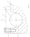
- the pin 6 is fixed in the lower bearing shell 7 by a upper, split bearing shell, which is formed from the bridge 8 and the clamping piece 9 becomes.
- the clamping piece 9 like the upper bearing shell 4 according to the known State of the art a receptacle 10 directed towards the pin 6, which has a play-free Enclosing the cylindrical upper half of the pin 6 allows.
- the side of the clamping piece 9 opposite the receptacle 10 is flat educated.
- the bridge 8 is arranged such that in the assembled state the pin / bearing connection, the bridge 8 on the lower bearing shell 7 is fixed by means of screws 12 and the clamping piece 9 with its flat Surface 11 of the underside of the bridge 8 is opposite. It points the bridge 8 is opposite the bearing surface 14 to the lower bearing shell 7 recessed flat area 13 on the receiving the clamping piece 9th serves, wherein a gap 15 is formed between the opposite surfaces is. In addition, there is a vertical one in this recessed area 13 Section 16 provided a slight vertical guidance of the clamping piece 9 in the bridge 8 allows.
- the clamping force is transmitted to the journal / bearing connection by means of of a pair of set screws 17 which are in vertical, spaced from the center line Threaded holes 18 are guided and the gap 15 when rotating bridge and with the flat surface 11 of the clamping piece 9 in contact come.
- a pair of set screws 17 which are in vertical, spaced from the center line Threaded holes 18 are guided and the gap 15 when rotating bridge and with the flat surface 11 of the clamping piece 9 in contact come.
- Threaded holes 18 are guided and the gap 15 when rotating bridge and with the flat surface 11 of the clamping piece 9 in contact come.
- the Adjustable clamping force is transmitted to the journal / bearing connection by means of of a pair of set screws 17 which are in vertical, spaced from the center line Threaded holes 18 are guided and the gap 15 when rotating bridge and with the flat surface 11 of the clamping piece 9 in contact come.
- the Adjustable clamping force is transmitted to the journal / bearing connection by means of of a pair of set screws 17 which are in vertical, spaced from the center
- a key advantage of this pin / bearing connection is that the resulting from the dynamic load on the coupling device Loosening of the connection by adjusting the clamping piece 9 by applying it the set screws 17 can be easily removed, without having to dismantle the pin / bearing connection.
- clamping piece 9 sees its division in front.
- the division of the clamping piece 9 takes place above the apex of the Pin 6.
- the elements for transmitting the clamping force are in this Embodiment arranged in the bridge 8 so that each section of the Clamping piece 9 is acted upon independently.
Landscapes
- Engineering & Computer Science (AREA)
- Mechanical Engineering (AREA)
- Pivots And Pivotal Connections (AREA)
- Seal Device For Vehicle (AREA)
- Harvester Elements (AREA)
- Quick-Acting Or Multi-Walled Pipe Joints (AREA)
- Automatic Cycles, And Cycles In General (AREA)
- Mutual Connection Of Rods And Tubes (AREA)
- Axle Suspensions And Sidecars For Cycles (AREA)
- Agricultural Machines (AREA)
Abstract
Description
- Fig. 1
- einen Querschnitt durch die Zapfenlagerung gemäß dem bekannten Stand der Technik,
- Fig. 2
- einen Querschnitt durch die erfindungsgemäße Zapfenlagerung.
- 1
- Wange
- 2
- untere Lagerschale
- 3
- Zapfen
- 4
- obere Lagerschale
- 5
- Schraube
- 6
- Zapfen
- 7
- untere Lagerschale
- 8
- Brücke
- 9
- Klemmstück
- 10
- Aufnahme
- 11
- Oberfläche
- 12
- Schraube
- 13
- ebener Bereich
- 14
- Auflagefläche
- 15
- Spalt
- 16
- vertikaler Abschnitt
- 17
- Stellschraube
- 18
- Gewindebohrung
Claims (5)
- Gelenkverbindung zwischen zwei gelenkig miteinander verbundenen Fahrzeugeinheiten eines schienengebundenen Gliederfahrzeuges mit einer als Gabelkopf ausgebildeten Kupplungshälfte, wobei jede der beiden Wangen des Gabelkopfes zur Aufnahme der Enden des Kupplungsbolzens in einem geteilten Zapfenlager mit oberer, lösbarer und unterer Lagerschale ausgestattet ist, dadurch gekennzeichnet, daß die obere lösbare Lagerschale aus einer mit der unteren Lagerschale (7) fest verbundenen Brücke (8) und einem darunter, durch einen Spalt (11) beabstandet angeordneten, mit dem Zapfen (6) in Wirkverbindung stehenden Klemmstück (9) gebildet wird, wobei in dem Spalt (11) Mittel zum gleichmäßigen Verdrängen des Klemmstückes (9) gegen den Zapfen (6) angeordnet sind.
- Gelenkverbindung nach Anspruch 1, dadurch gekennzeichnet, daß als Mittel zum Verdrängen des Klemmstückes (9) gegen den Zapfen (6) Stellschrauben (17) zum Einsatz gelangen, die über in der Brücke (8) angeordnete Gewindebohrungen (18) gegen das Klemmstück (9) verstellbar sind.
- Gelenkverbindung nach Anspruch 1, dadurch gekennzeichnet, daß als Mittel zum Verdrängen des Klemmstückes (9) gegen den Zapfen (6) Tellerfedern zum Einsatz gelangen.
- Gelenkverbindung nach Anspruch 1, dadurch gekennzeichnet, daß als Mittel zum Verdrängen des Klemmstückes (9) gegen den Zapfen (6) Spannscheiben zum Einsatz gelangen.
- Gelenkverbindung nach Anspruch 1, dadurch gekennzeichnet, daß das Klemmstück (9) oberhalb des Scheitelpunktes des Zapfens (6) geteilt ist, wobei jedes Teilstück durch Mittel zum Verdrängen gegen den Zapfen (6) beaufschlagbar ist.
Applications Claiming Priority (2)
| Application Number | Priority Date | Filing Date | Title |
|---|---|---|---|
| DE10006337A DE10006337A1 (de) | 2000-02-12 | 2000-02-12 | Gelenkverbindung zwischen zwei gelenkig miteinander verbundenen Fahrzeugeinheiten |
| DE10006337 | 2000-02-12 |
Publications (2)
| Publication Number | Publication Date |
|---|---|
| EP1123852A1 true EP1123852A1 (de) | 2001-08-16 |
| EP1123852B1 EP1123852B1 (de) | 2003-04-16 |
Family
ID=7630745
Family Applications (1)
| Application Number | Title | Priority Date | Filing Date |
|---|---|---|---|
| EP01102452A Expired - Lifetime EP1123852B1 (de) | 2000-02-12 | 2001-02-03 | Gelenkverbindung zwischen zwei gelenkig miteinander verbundenen Fahrzeugeinheiten |
Country Status (5)
| Country | Link |
|---|---|
| EP (1) | EP1123852B1 (de) |
| AT (1) | ATE237488T1 (de) |
| DE (2) | DE10006337A1 (de) |
| DK (1) | DK1123852T3 (de) |
| ES (1) | ES2193997T3 (de) |
Cited By (1)
| Publication number | Priority date | Publication date | Assignee | Title |
|---|---|---|---|---|
| WO2020193711A1 (en) * | 2019-03-26 | 2020-10-01 | Axtone Spolka Akcyjna | Flexible clamp |
Citations (3)
| Publication number | Priority date | Publication date | Assignee | Title |
|---|---|---|---|---|
| DE4121080A1 (de) * | 1991-06-26 | 1993-01-14 | Waggon Union Gmbh | Kupplungsvorrichtung fuer die auf einem gemeinsamen drehgestell abgestuetzten enden zweier gelenkig miteinander verbundener fahrzeugeinheiten |
| EP0582035A1 (de) * | 1992-08-04 | 1994-02-09 | Westinghouse Air Brake Company | Gelenkiger Kupplungsmechanismus |
| US5544767A (en) * | 1995-06-28 | 1996-08-13 | Westinghouse Air Brake Company | Freight railway car slackless drawbar assembly |
-
2000
- 2000-02-12 DE DE10006337A patent/DE10006337A1/de not_active Withdrawn
-
2001
- 2001-02-03 EP EP01102452A patent/EP1123852B1/de not_active Expired - Lifetime
- 2001-02-03 DK DK01102452T patent/DK1123852T3/da active
- 2001-02-03 ES ES01102452T patent/ES2193997T3/es not_active Expired - Lifetime
- 2001-02-03 DE DE50100163T patent/DE50100163D1/de not_active Expired - Lifetime
- 2001-02-03 AT AT01102452T patent/ATE237488T1/de active
Patent Citations (3)
| Publication number | Priority date | Publication date | Assignee | Title |
|---|---|---|---|---|
| DE4121080A1 (de) * | 1991-06-26 | 1993-01-14 | Waggon Union Gmbh | Kupplungsvorrichtung fuer die auf einem gemeinsamen drehgestell abgestuetzten enden zweier gelenkig miteinander verbundener fahrzeugeinheiten |
| EP0582035A1 (de) * | 1992-08-04 | 1994-02-09 | Westinghouse Air Brake Company | Gelenkiger Kupplungsmechanismus |
| US5544767A (en) * | 1995-06-28 | 1996-08-13 | Westinghouse Air Brake Company | Freight railway car slackless drawbar assembly |
Cited By (3)
| Publication number | Priority date | Publication date | Assignee | Title |
|---|---|---|---|---|
| WO2020193711A1 (en) * | 2019-03-26 | 2020-10-01 | Axtone Spolka Akcyjna | Flexible clamp |
| CN113631457A (zh) * | 2019-03-26 | 2021-11-09 | 艾克斯通股份公司 | 挠性夹具 |
| US11383741B2 (en) | 2019-03-26 | 2022-07-12 | Axtone S.A. | Flexible clamp |
Also Published As
| Publication number | Publication date |
|---|---|
| DK1123852T3 (da) | 2003-07-21 |
| DE50100163D1 (de) | 2003-05-22 |
| DE10006337A1 (de) | 2001-08-16 |
| EP1123852B1 (de) | 2003-04-16 |
| ATE237488T1 (de) | 2003-05-15 |
| ES2193997T3 (es) | 2003-11-16 |
Similar Documents
| Publication | Publication Date | Title |
|---|---|---|
| DE19680799C1 (de) | Osteosynthesehilfsmittel | |
| DE3883981T2 (de) | Biegsamer arm. | |
| EP1930533A1 (de) | Kraftfahrzeugtürscharnier | |
| WO2005023508A1 (de) | Düsenanpressvorrichtung | |
| CH713677B1 (de) | Anlenkungseinrichtung für eine Kupplung eines Schienenfahrzeugs. | |
| EP0510303B1 (de) | Vibrationsdämpfungselement an einer Waage | |
| DE19945197C1 (de) | Befestigungsvorrichtung für eine Glasscheibe | |
| EP0520301A1 (de) | Kupplungsvorrichtung für die auf einem gemeinsamen Drehgestell abgestützten Enden zweier gelenkig miteinander verbundener Fahrzeugeinheiten | |
| EP3072773B1 (de) | Fahrzeug mit gelenkiger anbindung einer kuppelstange | |
| DE4436484C2 (de) | Schwenkbare Befestigungsvorrichtung zur Befestigung von Gebäudeplatten | |
| DE69910168T2 (de) | Befestigung einer starrachse für ein fahrzeug | |
| EP3649356A1 (de) | Gelenk | |
| EP1123852B1 (de) | Gelenkverbindung zwischen zwei gelenkig miteinander verbundenen Fahrzeugeinheiten | |
| EP0857278B1 (de) | Neigungsadapter für ein tragarmsystem | |
| DE4211180C2 (de) | Formschlüssiges, einstellbares Verbindungsteil zum Anschließen von freiauskragenden Gepäckträgern an Kugelkopfkupplungen | |
| DE20002517U1 (de) | Gelenkverbindung zwischen zwei gelenkig miteinander verbundenen Fahrzeugeinheiten | |
| DE102006035517B3 (de) | Spanneinrichtung zum Spannen von Blechplatinen in einer Schweißvorrichtung | |
| EP3539850B1 (de) | Achskörper mit einem über ein drehgelenk verbundenen lenkbaren radträger | |
| DE102005062057A1 (de) | Tretroller | |
| DE19840426B4 (de) | Lenksäulenlagerung | |
| DE8429553U1 (de) | Kraftfahrzeug mit einem rahmen und einem aufbau | |
| DE3524255C2 (de) | ||
| CH687744A5 (de) | Schwingschleifer. | |
| EP0920935A2 (de) | Traggerüst für eine oszillierende Kokille | |
| DE2313745A1 (de) | Gelenkverbindung zwischen wenigstes zwei getriebeteilen |
Legal Events
| Date | Code | Title | Description |
|---|---|---|---|
| PUAI | Public reference made under article 153(3) epc to a published international application that has entered the european phase |
Free format text: ORIGINAL CODE: 0009012 |
|
| AK | Designated contracting states |
Kind code of ref document: A1 Designated state(s): AT BE CH CY DE DK ES FI FR GB GR IE IT LI LU MC NL PT SE TR |
|
| AX | Request for extension of the european patent |
Free format text: AL;LT;LV;MK;RO;SI |
|
| 17P | Request for examination filed |
Effective date: 20011206 |
|
| AKX | Designation fees paid |
Free format text: AT BE CH CY DE DK ES FI FR GB GR IE IT LI LU MC NL PT SE TR |
|
| GRAH | Despatch of communication of intention to grant a patent |
Free format text: ORIGINAL CODE: EPIDOS IGRA |
|
| GRAH | Despatch of communication of intention to grant a patent |
Free format text: ORIGINAL CODE: EPIDOS IGRA |
|
| GRAA | (expected) grant |
Free format text: ORIGINAL CODE: 0009210 |
|
| AK | Designated contracting states |
Designated state(s): AT BE CH CY DE DK ES FI FR GB GR IE IT LI LU MC NL PT SE TR |
|
| PG25 | Lapsed in a contracting state [announced via postgrant information from national office to epo] |
Ref country code: FI Free format text: LAPSE BECAUSE OF FAILURE TO SUBMIT A TRANSLATION OF THE DESCRIPTION OR TO PAY THE FEE WITHIN THE PRESCRIBED TIME-LIMIT Effective date: 20030416 Ref country code: IE Free format text: LAPSE BECAUSE OF NON-PAYMENT OF DUE FEES Effective date: 20030416 Ref country code: CY Free format text: LAPSE BECAUSE OF FAILURE TO SUBMIT A TRANSLATION OF THE DESCRIPTION OR TO PAY THE FEE WITHIN THE PRESCRIBED TIME-LIMIT Effective date: 20030416 Ref country code: TR Free format text: LAPSE BECAUSE OF FAILURE TO SUBMIT A TRANSLATION OF THE DESCRIPTION OR TO PAY THE FEE WITHIN THE PRESCRIBED TIME-LIMIT Effective date: 20030416 |
|
| REG | Reference to a national code |
Ref country code: GB Ref legal event code: FG4D Free format text: NOT ENGLISH |
|
| REG | Reference to a national code |
Ref country code: CH Ref legal event code: EP |
|
| REF | Corresponds to: |
Ref document number: 50100163 Country of ref document: DE Date of ref document: 20030522 Kind code of ref document: P |
|
| REG | Reference to a national code |
Ref country code: IE Ref legal event code: FG4D Free format text: GERMAN |
|
| REG | Reference to a national code |
Ref country code: CH Ref legal event code: NV Representative=s name: SCHMAUDER & PARTNER AG PATENTANWALTSBUERO |
|
| PG25 | Lapsed in a contracting state [announced via postgrant information from national office to epo] |
Ref country code: GR Free format text: LAPSE BECAUSE OF FAILURE TO SUBMIT A TRANSLATION OF THE DESCRIPTION OR TO PAY THE FEE WITHIN THE PRESCRIBED TIME-LIMIT Effective date: 20030716 Ref country code: PT Free format text: LAPSE BECAUSE OF FAILURE TO SUBMIT A TRANSLATION OF THE DESCRIPTION OR TO PAY THE FEE WITHIN THE PRESCRIBED TIME-LIMIT Effective date: 20030716 |
|
| REG | Reference to a national code |
Ref country code: DK Ref legal event code: T3 |
|
| REG | Reference to a national code |
Ref country code: SE Ref legal event code: TRGR |
|
| GBT | Gb: translation of ep patent filed (gb section 77(6)(a)/1977) |
Effective date: 20030715 |
|
| REG | Reference to a national code |
Ref country code: ES Ref legal event code: FG2A Ref document number: 2193997 Country of ref document: ES Kind code of ref document: T3 |
|
| REG | Reference to a national code |
Ref country code: IE Ref legal event code: FD4D Ref document number: 1123852E Country of ref document: IE |
|
| ET | Fr: translation filed | ||
| PG25 | Lapsed in a contracting state [announced via postgrant information from national office to epo] |
Ref country code: LU Free format text: LAPSE BECAUSE OF NON-PAYMENT OF DUE FEES Effective date: 20040203 |
|
| PLBE | No opposition filed within time limit |
Free format text: ORIGINAL CODE: 0009261 |
|
| STAA | Information on the status of an ep patent application or granted ep patent |
Free format text: STATUS: NO OPPOSITION FILED WITHIN TIME LIMIT |
|
| PG25 | Lapsed in a contracting state [announced via postgrant information from national office to epo] |
Ref country code: MC Free format text: LAPSE BECAUSE OF NON-PAYMENT OF DUE FEES Effective date: 20040228 |
|
| 26N | No opposition filed |
Effective date: 20040119 |
|
| REG | Reference to a national code |
Ref country code: CH Ref legal event code: PCAR Free format text: SCHMAUDER & PARTNER AG PATENT- UND MARKENANWAELTE VSP;ZWAENGIWEG 7;8038 ZUERICH (CH) |
|
| REG | Reference to a national code |
Ref country code: ES Ref legal event code: PC2A |
|
| REG | Reference to a national code |
Ref country code: FR Ref legal event code: PLFP Year of fee payment: 16 |
|
| REG | Reference to a national code |
Ref country code: FR Ref legal event code: PLFP Year of fee payment: 17 |
|
| REG | Reference to a national code |
Ref country code: FR Ref legal event code: PLFP Year of fee payment: 18 |
|
| PGFP | Annual fee paid to national office [announced via postgrant information from national office to epo] |
Ref country code: DE Payment date: 20200219 Year of fee payment: 20 Ref country code: NL Payment date: 20200219 Year of fee payment: 20 Ref country code: DK Payment date: 20200224 Year of fee payment: 20 Ref country code: IT Payment date: 20200225 Year of fee payment: 20 Ref country code: AT Payment date: 20200220 Year of fee payment: 20 Ref country code: GB Payment date: 20200219 Year of fee payment: 20 Ref country code: ES Payment date: 20200322 Year of fee payment: 20 Ref country code: SE Payment date: 20200220 Year of fee payment: 20 |
|
| PGFP | Annual fee paid to national office [announced via postgrant information from national office to epo] |
Ref country code: CH Payment date: 20200219 Year of fee payment: 20 Ref country code: BE Payment date: 20200219 Year of fee payment: 20 |
|
| PGFP | Annual fee paid to national office [announced via postgrant information from national office to epo] |
Ref country code: FR Payment date: 20200219 Year of fee payment: 20 |
|
| REG | Reference to a national code |
Ref country code: NL Ref legal event code: MK Effective date: 20210202 Ref country code: DE Ref legal event code: R071 Ref document number: 50100163 Country of ref document: DE |
|
| REG | Reference to a national code |
Ref country code: DK Ref legal event code: EUP Expiry date: 20210203 |
|
| REG | Reference to a national code |
Ref country code: CH Ref legal event code: PL |
|
| REG | Reference to a national code |
Ref country code: GB Ref legal event code: PE20 Expiry date: 20210202 |
|
| REG | Reference to a national code |
Ref country code: AT Ref legal event code: MK07 Ref document number: 237488 Country of ref document: AT Kind code of ref document: T Effective date: 20210203 |
|
| REG | Reference to a national code |
Ref country code: SE Ref legal event code: EUG |
|
| REG | Reference to a national code |
Ref country code: BE Ref legal event code: MK Effective date: 20210203 |
|
| PG25 | Lapsed in a contracting state [announced via postgrant information from national office to epo] |
Ref country code: GB Free format text: LAPSE BECAUSE OF EXPIRATION OF PROTECTION Effective date: 20210202 |
|
| REG | Reference to a national code |
Ref country code: ES Ref legal event code: FD2A Effective date: 20211229 |
|
| PG25 | Lapsed in a contracting state [announced via postgrant information from national office to epo] |
Ref country code: ES Free format text: LAPSE BECAUSE OF EXPIRATION OF PROTECTION Effective date: 20210204 |