EP1124040A1 - Actionneur électromagnétique pour soupape - Google Patents
Actionneur électromagnétique pour soupape Download PDFInfo
- Publication number
- EP1124040A1 EP1124040A1 EP00102860A EP00102860A EP1124040A1 EP 1124040 A1 EP1124040 A1 EP 1124040A1 EP 00102860 A EP00102860 A EP 00102860A EP 00102860 A EP00102860 A EP 00102860A EP 1124040 A1 EP1124040 A1 EP 1124040A1
- Authority
- EP
- European Patent Office
- Prior art keywords
- valve
- housing
- plate
- train according
- spring
- Prior art date
- Legal status (The legal status is an assumption and is not a legal conclusion. Google has not performed a legal analysis and makes no representation as to the accuracy of the status listed.)
- Withdrawn
Links
- 238000002485 combustion reaction Methods 0.000 claims description 7
- 238000010521 absorption reaction Methods 0.000 claims 1
- 238000012423 maintenance Methods 0.000 description 2
- 125000006850 spacer group Chemical group 0.000 description 2
- 230000005540 biological transmission Effects 0.000 description 1
- 230000006835 compression Effects 0.000 description 1
- 238000007906 compression Methods 0.000 description 1
- 230000000694 effects Effects 0.000 description 1
- 238000004519 manufacturing process Methods 0.000 description 1
- 238000000034 method Methods 0.000 description 1
Images

Classifications
-
- F—MECHANICAL ENGINEERING; LIGHTING; HEATING; WEAPONS; BLASTING
- F01—MACHINES OR ENGINES IN GENERAL; ENGINE PLANTS IN GENERAL; STEAM ENGINES
- F01L—CYCLICALLY OPERATING VALVES FOR MACHINES OR ENGINES
- F01L3/00—Lift-valve, i.e. cut-off apparatus with closure members having at least a component of their opening and closing motion perpendicular to the closing faces; Parts or accessories thereof
- F01L3/08—Valves guides; Sealing of valve stem, e.g. sealing by lubricant
-
- F—MECHANICAL ENGINEERING; LIGHTING; HEATING; WEAPONS; BLASTING
- F01—MACHINES OR ENGINES IN GENERAL; ENGINE PLANTS IN GENERAL; STEAM ENGINES
- F01L—CYCLICALLY OPERATING VALVES FOR MACHINES OR ENGINES
- F01L9/00—Valve-gear or valve arrangements actuated non-mechanically
- F01L9/20—Valve-gear or valve arrangements actuated non-mechanically by electric means
-
- F—MECHANICAL ENGINEERING; LIGHTING; HEATING; WEAPONS; BLASTING
- F01—MACHINES OR ENGINES IN GENERAL; ENGINE PLANTS IN GENERAL; STEAM ENGINES
- F01L—CYCLICALLY OPERATING VALVES FOR MACHINES OR ENGINES
- F01L2800/00—Methods of operation using a variable valve timing mechanism
- F01L2800/09—Calibrating
Definitions
- the invention relates to an electromagnetic valve train for a gas exchange valve an internal combustion engine, with a plate-shaped attached to the valve stem Magnetic armature and electromagnets arranged on both sides of the armature Execution of valve movements and for holding the valve in the opening and Closed position in connection with one in the opening direction and one in Valve spring acting in the closing direction of the valve.
- Proposed solutions for controlling gas exchange valves in internal combustion engines with the help of electromagnets belong to the prior art.
- an electromagnet By entering or Turning off an electromagnet can be an armature that is used for power transmission is connected to the gas exchange valve by an electromagnet, for example from the closed position, release and supported by spring force via the middle position move out near the opposite electromagnet, passing through Appropriate control is ensured that the gas exchange valve in its Open position is pulled. To close the same process in executed in reverse order. The gas exchange valve is always in its Open and held in its closed position. Examples of this principle Working internal combustion engines with gas exchange valves are described in DE 30 24 109 C2, DE 33 11 250 C2, DE 35 00 530 C2, DE 43 36 287 C1 u. a. described.
- Electromagnetic valve trains face opposite conventional designs on additional components.
- the assembly, Adjustment of the individual parts and maintenance work are also disadvantageous in the Compared to conventional valve trains.
- the exact setting of the The middle position of the magnet armature between the magnet coils is partly with a considerable work involved.
- the invention has for its object an electromagnetic working To create valve train, its height and the number of components required are reduced.
- the assembly and adjustment of the anchor center position should be made easier become.
- Overall, the aim is to improve the ease of maintenance.
- the invention solves this problem by the features of claim 1.
- the solution according to the invention leads in particular through the design of the magnet armature plate at the same time as a spring plate to a significant reduction in the number of components required, in particular because the force application of the two oppositely acting valve springs takes place directly on the armature plate. This also allows the overall height to be significantly reduced compared to the known electromagnetic valve drives.
- the attachment of the magnetic armature plate directly to the valve stem serves, according to a further proposal, a non-positive or positive double-cone connection, so that the compressive forces can be directed into the valve stem in two opposite directions. This ensures a direct effect of the magnetic and / or valve forces exerted on the armature on the valve.
- the valve can be freely rotated during its movement.
- the setting of the exact center position of the magnetic armature plate between the Electromagnets can be adjusted by adjusting the electromagnets against the Valve stem fixed anchor are made. At the same time, the A necessary valve clearance is set, which in turn is used for Noise reduction helps.
- valve spring forces adjustable via a screw ring located in the housing cover To make valve spring forces adjustable via a screw ring located in the housing cover.
- the exact center position of the armature can be set in a simple manner by adjusting the housing with the electromagnets fixed therein, a screw ring having two oppositely acting threaded sections being provided. This screw ring connects the housing with the bridge supporting the entire unit. In order to switch off the thread play of this screw connection, a disc spring can be inserted between the bridge and the housing.
- valve train designed according to the invention it is possible to use the valve train designed according to the invention as one completely pre-assembled unit, which makes a clear Assembly simplification can be achieved. If necessary, however, the
- the individual components can be installed directly in the cylinder head.
- the electromagnets belong to the completely pre-assembled unit reciprocating valve springs, the magnet armature plate, a spacer sleeve between the solenoids for valve lift adjustment, the Spring force adjustment device and the cover plate of the housing with a central one
- the pre-assembled electromagnetic valve train can be flanged by The edges of the housing must be firmly closed around the edges of the cover plate.
- the optimal Adjusting the opposing valve spring forces can be done before installing the Housing in the cylinder head can already be made in the manufacturing plant.
- the gas exchange valve 1 is at the free end of its shaft 2 with a Magnetic armature plate 3 equipped, the 4 or double cone pieces is non-positively connected to the valve stem.
- the double cone pieces are in a conical bore 5 of the anchor plate and in a conical bore 6 one Clamping bush 7 fixed.
- the clamping bush engages with an external thread 8 corresponding thread of the anchor plate 3.
- the magnetic armature plate 3 also serves as a spring plate for the opening direction acting spring 9 and the opposite, that is, in the closing direction acting valve spring 10.
- the two electromagnets 11 and 12 are by a Spacer sleeve 13 held at the required distance, the
- the valve train consisting of the aforementioned elements is enclosed by a housing or cage 14 and closed by a cover 15.
- the upper housing edges can be bent or crimped around the edge of the cover.
- a screw ring 16 provided with an internal hexagon engages in the cover 15 with a central screw opening and serves as an adjustable spring support for the opening valve spring 9.
- the exact setting of the screw ring via its thread 17 enables a precise spring force setting, which can already be adjusted in the factory.
- the exact setting of the spring force of the spring 10 takes place via the setting disk 27.
- the shields A and B prevent an inadmissible influence of the magnetic field on the moving part of the valve springs.
- the entire assembly with the cage 14 can be fastened to the cylinder head 19, not shown, of an internal combustion engine via a holding bridge 18.
- a compression spring 23, in particular a plate spring, acting in the axial direction can be placed between the bridge 18 and the cover 15. An unintentional adjustment is avoided by means of the lock nut 28.
- the assembly unit is guided via the valve guide 24 with the valve seal 25, which are firmly connected to the cylinder head.
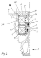
- FIG. 2 differs from that of FIG. 1 essentially by the rotationally symmetrical embodiment and an additional valve guide 30 in the region of the connection of the housing 14 to the plate 35.
- the valve stem 2 is beyond the groove recesses 31 for the engagement of the double cone pieces 4 extended into the area of the second valve guide 30.
- This part of the valve stem is marked with 2 a.
- the housing 14 is screwed directly onto the thread 34 in the cylinder head.
- the plate 35 serves to avoid thread play and is also countered by thread 36 directly in the cylinder head against part 15.
- the cone of the double cone pieces facing the cover 15 is in one Fixed cone of a clamping plate 32 which is screwed to the anchor plate 3.
- the preassembled housing 14, 15 is first inserted into the cylinder head set and connected to it by the holding bridge 18. Then that will Valve inserted. Then the double cone pieces are placed on the valve stem, the armature 3 analogous to the spring plate in a conventional Tapered piece assembly is moved against the force of the closing spring 10. After Return of the magnetic armature plate 3 to its initial position fixes it Double cone pieces on the valve stem. By screwing the clamping bush 7 with the Magnetic anchor plate 3, the double cone pieces are finally in both Direction of movement resilient due to compressive forces.
- the center position of the is adjusted precisely Magnetic anchor plate by adjusting the pre-assembled unit in the direction of the valve stem with the help of the two oppositely acting threaded sections 21 and 22 of the Screw ring 20. Its screw rotations produce a relative movement of the Housing with the electromagnets to the magnet armature plate. About adjusting the The middle position can also be used to adjust the valve clearance required for the valve Compensation of the thermal valve expansion take place.
Landscapes
- Engineering & Computer Science (AREA)
- Mechanical Engineering (AREA)
- General Engineering & Computer Science (AREA)
- Valve Device For Special Equipments (AREA)
- Magnetically Actuated Valves (AREA)
Priority Applications (1)
| Application Number | Priority Date | Filing Date | Title |
|---|---|---|---|
| EP00102860A EP1124040A1 (fr) | 2000-02-11 | 2000-02-11 | Actionneur électromagnétique pour soupape |
Applications Claiming Priority (1)
| Application Number | Priority Date | Filing Date | Title |
|---|---|---|---|
| EP00102860A EP1124040A1 (fr) | 2000-02-11 | 2000-02-11 | Actionneur électromagnétique pour soupape |
Publications (1)
| Publication Number | Publication Date |
|---|---|
| EP1124040A1 true EP1124040A1 (fr) | 2001-08-16 |
Family
ID=8167833
Family Applications (1)
| Application Number | Title | Priority Date | Filing Date |
|---|---|---|---|
| EP00102860A Withdrawn EP1124040A1 (fr) | 2000-02-11 | 2000-02-11 | Actionneur électromagnétique pour soupape |
Country Status (1)
| Country | Link |
|---|---|
| EP (1) | EP1124040A1 (fr) |
Cited By (4)
| Publication number | Priority date | Publication date | Assignee | Title |
|---|---|---|---|---|
| DE10141176A1 (de) * | 2001-08-22 | 2003-03-20 | Bosch Gmbh Robert | Lösbare Verbindung zum Kuppeln eines Gaswechselventils einer Brennkraftmaschine mit einem Aktor |
| WO2007135528A1 (fr) * | 2006-05-19 | 2007-11-29 | Toyota Jidosha Kabushiki Kaisha | Soupape à commande électromagnétique |
| FR2990465A1 (fr) * | 2012-05-14 | 2013-11-15 | Valeo Sys Controle Moteur Sas | Ensemble de levee multiple de soupape |
| CN113586196A (zh) * | 2021-08-30 | 2021-11-02 | 山东大学 | 一种内燃机的可变气门结构 |
Citations (7)
| Publication number | Priority date | Publication date | Assignee | Title |
|---|---|---|---|---|
| GB2137420A (en) * | 1983-03-28 | 1984-10-03 | Fev Forsch Energietech Verbr | Electromagnetically-operated adjusting means |
| DE3024109C2 (fr) | 1980-06-27 | 1989-09-28 | Pischinger, Franz, Prof. Dipl.-Ing. Dr.Techn., 5100 Aachen, De | |
| DE3500530C2 (fr) | 1985-01-09 | 1989-12-21 | Binder Magnete Gmbh, 7730 Villingen-Schwenningen, De | |
| DE4336287C1 (de) | 1993-10-25 | 1995-03-02 | Daimler Benz Ag | Vorrichtung zur elektromagnetischen Betätigung eines Gaswechselventils |
| WO1995030104A1 (fr) * | 1994-04-28 | 1995-11-09 | Aura Systems, Inc. | Modele de soupapes echelonnees a actionnement electromagnetique |
| JPH08135417A (ja) * | 1994-11-10 | 1996-05-28 | Toyota Motor Corp | 内燃機関の電磁駆動式バルブ装置 |
| JPH1037726A (ja) * | 1996-07-24 | 1998-02-10 | Honda Motor Co Ltd | 内燃機関の動弁装置 |
-
2000
- 2000-02-11 EP EP00102860A patent/EP1124040A1/fr not_active Withdrawn
Patent Citations (8)
| Publication number | Priority date | Publication date | Assignee | Title |
|---|---|---|---|---|
| DE3024109C2 (fr) | 1980-06-27 | 1989-09-28 | Pischinger, Franz, Prof. Dipl.-Ing. Dr.Techn., 5100 Aachen, De | |
| GB2137420A (en) * | 1983-03-28 | 1984-10-03 | Fev Forsch Energietech Verbr | Electromagnetically-operated adjusting means |
| DE3311250C2 (de) | 1983-03-28 | 1985-08-01 | FEV Forschungsgesellschaft für Energietechnik und Verbrennungsmotoren mbH, 5100 Aachen | Vorrichtung zur elektromagnetischen Betätigung eines Gaswechselventils für Verdrängungsmaschinen |
| DE3500530C2 (fr) | 1985-01-09 | 1989-12-21 | Binder Magnete Gmbh, 7730 Villingen-Schwenningen, De | |
| DE4336287C1 (de) | 1993-10-25 | 1995-03-02 | Daimler Benz Ag | Vorrichtung zur elektromagnetischen Betätigung eines Gaswechselventils |
| WO1995030104A1 (fr) * | 1994-04-28 | 1995-11-09 | Aura Systems, Inc. | Modele de soupapes echelonnees a actionnement electromagnetique |
| JPH08135417A (ja) * | 1994-11-10 | 1996-05-28 | Toyota Motor Corp | 内燃機関の電磁駆動式バルブ装置 |
| JPH1037726A (ja) * | 1996-07-24 | 1998-02-10 | Honda Motor Co Ltd | 内燃機関の動弁装置 |
Non-Patent Citations (2)
| Title |
|---|
| PATENT ABSTRACTS OF JAPAN vol. 1996, no. 09 30 September 1996 (1996-09-30) * |
| PATENT ABSTRACTS OF JAPAN vol. 1998, no. 06 30 April 1998 (1998-04-30) * |
Cited By (5)
| Publication number | Priority date | Publication date | Assignee | Title |
|---|---|---|---|---|
| DE10141176A1 (de) * | 2001-08-22 | 2003-03-20 | Bosch Gmbh Robert | Lösbare Verbindung zum Kuppeln eines Gaswechselventils einer Brennkraftmaschine mit einem Aktor |
| WO2007135528A1 (fr) * | 2006-05-19 | 2007-11-29 | Toyota Jidosha Kabushiki Kaisha | Soupape à commande électromagnétique |
| FR2990465A1 (fr) * | 2012-05-14 | 2013-11-15 | Valeo Sys Controle Moteur Sas | Ensemble de levee multiple de soupape |
| WO2013171392A1 (fr) * | 2012-05-14 | 2013-11-21 | Valeo Systemes De Controle Moteur | Module de levée multiple de soupape et système d'actionnement comportant ce module |
| CN113586196A (zh) * | 2021-08-30 | 2021-11-02 | 山东大学 | 一种内燃机的可变气门结构 |
Similar Documents
| Publication | Publication Date | Title |
|---|---|---|
| DE69310261T2 (de) | Proportionales, elektromagnetisch gesteuertes Ventil | |
| DE3616540C2 (fr) | ||
| DE602005002126T2 (de) | Verstellbares Dosierservoventil eines Einspritzventils | |
| DE19702458A1 (de) | Elektromagnetischer Aktuator für ein Gaswechselventil mit Ventilspielausgleich | |
| DE3513105A1 (de) | Elektromagnetische stelleinrichtung fuer gaswechselventile | |
| EP0796981A1 (fr) | Dispositif de commande électromagnétique pour soupape de moteur à combustion interne | |
| EP2220413A1 (fr) | Unité de commande électromagnétique pour une électrovanne et procédé de fabrication de ladite unité de commande | |
| EP1400658A1 (fr) | Turbocompresseur | |
| EP0317725A1 (fr) | Dispositif de commande de soupape champignon | |
| EP1069285B1 (fr) | Dispositif électromagnétique pour actionner une soupape de gaz avec des ressorts concentriquement emboítés | |
| DE29620741U1 (de) | Schmalbauender elektromagnetischer Aktuator | |
| DE3521040A1 (de) | Einspritzventil | |
| EP1124040A1 (fr) | Actionneur électromagnétique pour soupape | |
| DE19750228C1 (de) | Vorrichtung zum Betätigen eines Gaswechselventils mit einem elektromagnetischen Aktuator | |
| EP0284634A1 (fr) | Dispositif de positionnement électromécanique | |
| DE19607019A1 (de) | Vorrichtung zur elektromagnetischen Betätigung eines Gaswechselventiles für Verbrennungsmotoren | |
| DE19811779C1 (de) | Vorrichtung zum Betätigen eines Gaswechselventils für eine Brennkraftmaschine | |
| DE3920893C2 (fr) | ||
| DE102011012020B4 (de) | Nockenwelle mit Nockenwellenversteller | |
| DE19845684C2 (de) | Stellungsregler für einen druckmittelbetriebenen Stellantrieb | |
| EP2199548B1 (fr) | Dispositif de rappel d'un déphaseur pour un arbre à came | |
| DE4219435A1 (de) | Einrichtung zum Abschalten eines von einem Tassenstößel betätigten Ventils einer Brennkraftmaschine | |
| DE29700096U1 (de) | Elektromagnetischer Aktuator zur Betätigung eines Gaswechselventils mit Dämpfungsmitteln zur Verminderung der Körperschallübertragung | |
| DE19728348C2 (de) | Vorrichtung für eine elektromagnetische Ventilsteuerung | |
| DE19723520A1 (de) | Verfahren zum lagerichtigen Fixieren einer Ankerplatte einer elektromagnetischen Ventilsteuerung, sowie elektromagnetische Ventilsteuerung |
Legal Events
| Date | Code | Title | Description |
|---|---|---|---|
| PUAI | Public reference made under article 153(3) epc to a published international application that has entered the european phase |
Free format text: ORIGINAL CODE: 0009012 |
|
| AK | Designated contracting states |
Kind code of ref document: A1 Designated state(s): DE FR GB IT SE |
|
| AX | Request for extension of the european patent |
Free format text: AL;LT;LV;MK;RO;SI |
|
| AKX | Designation fees paid |
Free format text: DE FR GB IT SE |
|
| STAA | Information on the status of an ep patent application or granted ep patent |
Free format text: STATUS: THE APPLICATION HAS BEEN WITHDRAWN |
|
| 18W | Application withdrawn |
Withdrawal date: 20020510 |