EP2199548B1 - Dispositif de rappel d'un déphaseur pour un arbre à came - Google Patents
Dispositif de rappel d'un déphaseur pour un arbre à came Download PDFInfo
- Publication number
- EP2199548B1 EP2199548B1 EP08021879A EP08021879A EP2199548B1 EP 2199548 B1 EP2199548 B1 EP 2199548B1 EP 08021879 A EP08021879 A EP 08021879A EP 08021879 A EP08021879 A EP 08021879A EP 2199548 B1 EP2199548 B1 EP 2199548B1
- Authority
- EP
- European Patent Office
- Prior art keywords
- springs
- cam shaft
- spring
- omega
- cap
- Prior art date
- Legal status (The legal status is an assumption and is not a legal conclusion. Google has not performed a legal analysis and makes no representation as to the accuracy of the status listed.)
- Active
Links
Images



Classifications
-
- F—MECHANICAL ENGINEERING; LIGHTING; HEATING; WEAPONS; BLASTING
- F01—MACHINES OR ENGINES IN GENERAL; ENGINE PLANTS IN GENERAL; STEAM ENGINES
- F01L—CYCLICALLY OPERATING VALVES FOR MACHINES OR ENGINES
- F01L1/00—Valve-gear or valve arrangements, e.g. lift-valve gear
- F01L1/34—Valve-gear or valve arrangements, e.g. lift-valve gear characterised by the provision of means for changing the timing of the valves without changing the duration of opening and without affecting the magnitude of the valve lift
- F01L1/344—Valve-gear or valve arrangements, e.g. lift-valve gear characterised by the provision of means for changing the timing of the valves without changing the duration of opening and without affecting the magnitude of the valve lift changing the angular relationship between crankshaft and camshaft, e.g. using helicoidal gear
- F01L1/3442—Valve-gear or valve arrangements, e.g. lift-valve gear characterised by the provision of means for changing the timing of the valves without changing the duration of opening and without affecting the magnitude of the valve lift changing the angular relationship between crankshaft and camshaft, e.g. using helicoidal gear using hydraulic chambers with variable volume to transmit the rotating force
-
- F—MECHANICAL ENGINEERING; LIGHTING; HEATING; WEAPONS; BLASTING
- F01—MACHINES OR ENGINES IN GENERAL; ENGINE PLANTS IN GENERAL; STEAM ENGINES
- F01L—CYCLICALLY OPERATING VALVES FOR MACHINES OR ENGINES
- F01L1/00—Valve-gear or valve arrangements, e.g. lift-valve gear
- F01L1/34—Valve-gear or valve arrangements, e.g. lift-valve gear characterised by the provision of means for changing the timing of the valves without changing the duration of opening and without affecting the magnitude of the valve lift
- F01L1/344—Valve-gear or valve arrangements, e.g. lift-valve gear characterised by the provision of means for changing the timing of the valves without changing the duration of opening and without affecting the magnitude of the valve lift changing the angular relationship between crankshaft and camshaft, e.g. using helicoidal gear
- F01L1/34409—Valve-gear or valve arrangements, e.g. lift-valve gear characterised by the provision of means for changing the timing of the valves without changing the duration of opening and without affecting the magnitude of the valve lift changing the angular relationship between crankshaft and camshaft, e.g. using helicoidal gear by torque-responsive means
-
- F—MECHANICAL ENGINEERING; LIGHTING; HEATING; WEAPONS; BLASTING
- F16—ENGINEERING ELEMENTS AND UNITS; GENERAL MEASURES FOR PRODUCING AND MAINTAINING EFFECTIVE FUNCTIONING OF MACHINES OR INSTALLATIONS; THERMAL INSULATION IN GENERAL
- F16F—SPRINGS; SHOCK-ABSORBERS; MEANS FOR DAMPING VIBRATION
- F16F1/00—Springs
- F16F1/02—Springs made of steel or other material having low internal friction; Wound, torsion, leaf, cup, ring or the like springs, the material of the spring not being relevant
- F16F1/025—Springs made of steel or other material having low internal friction; Wound, torsion, leaf, cup, ring or the like springs, the material of the spring not being relevant characterised by having a particular shape
-
- F—MECHANICAL ENGINEERING; LIGHTING; HEATING; WEAPONS; BLASTING
- F01—MACHINES OR ENGINES IN GENERAL; ENGINE PLANTS IN GENERAL; STEAM ENGINES
- F01L—CYCLICALLY OPERATING VALVES FOR MACHINES OR ENGINES
- F01L1/00—Valve-gear or valve arrangements, e.g. lift-valve gear
- F01L1/34—Valve-gear or valve arrangements, e.g. lift-valve gear characterised by the provision of means for changing the timing of the valves without changing the duration of opening and without affecting the magnitude of the valve lift
- F01L1/344—Valve-gear or valve arrangements, e.g. lift-valve gear characterised by the provision of means for changing the timing of the valves without changing the duration of opening and without affecting the magnitude of the valve lift changing the angular relationship between crankshaft and camshaft, e.g. using helicoidal gear
- F01L1/3442—Valve-gear or valve arrangements, e.g. lift-valve gear characterised by the provision of means for changing the timing of the valves without changing the duration of opening and without affecting the magnitude of the valve lift changing the angular relationship between crankshaft and camshaft, e.g. using helicoidal gear using hydraulic chambers with variable volume to transmit the rotating force
- F01L2001/3445—Details relating to the hydraulic means for changing the angular relationship
- F01L2001/34483—Phaser return springs
Definitions
- the invention relates to a device for resetting a phase adjuster of a camshaft, with a deferred to the free end of a cam phaser, in whose housing provided with an opening bottom fixed to the housing bottom rotatable lid to the camshaft rests, and with a force acting between the camshaft and cover spring Generation of a return torque.
- phase adjusters as shown in the example in the DE 10 2006 009 192 A1 . DE 10 2004 061 710 A1 . DE 10 2007 019 920 A1 . DE 60 2005 001 122 T2 are described throughout, use coil springs or compression springs for the generation of restoring moments.
- From the DE 10 2006 009 192 A1 is an adjusting device for an internal combustion engine having a control range having adjusting means for adjusting the phase position between a drive means and a non-rotatably connected to the drive means drive means and with a system which is provided in an emergency mode and / or when switching off the internal combustion engine, the adjusting device to lock and unlock the adjustment for normal operation of the internal combustion engine.
- the switching element disclosed in this known prior art consists of a spring element which can assume two stable end positions, namely an unlocking position and a locking position.
- the DE 10 2006 061 710 A1 describes a camshaft adjusting device with a hydraulic actuating means and a locking element for locking a camshaft-fixed component with a crankshaft-fixed component and an actuatable by means of an electromagnet hydraulic valve.
- a return spring is provided on the adjusting means to retract the locking element in its locking position.
- the locking takes place via a pin which is received in an axial bore of the inner rotor.
- the pin is pressed by the spring force of a compression spring in one of the formed in the side wall in the form of an axial bore locking receptacle, so that by the pin in the locking receptacle a relative Rotary adjustment between inner and outer rotor is prevented.
- the lock is released when, by the pressurization of the pressure chamber, the compression spring against the spring force of the compression spring pushes the pin from its locking receptacle.
- a bolt locking mechanism which includes a return spring to tension an end of the bolt in a hardened seat, which is arranged in the pulley or in the sprocket of the phaser, whereby the rotor is locked with respect to the stator. Rotor and stator are unlocked against the force of a return spring.
- the present invention seeks to develop a spring element for the provision of a phase adjuster, which leads to a lower height, requires less material, easier to assemble and at the same time a significant increase in the life allowed.
- the solution according to the invention is based on the recognition that the connection of the two anchoring points of the spring element in the plane of the disk-shaped cover leads to a considerable reduction of the overall height of the spring and a maximum restoring moment and a maximum tensile stress in the farthest cross section to the point of introduction of force at omega Springs with uniform load stress is achieved.
- a symmetrical to the camshaft arranged omega spring pair is connected non-positively with a camshaft fixed to the lid.
- Each omega single spring has an internal anchoring point defined in the camshaft and an anchoring point close to the outer circumference of the disc, diametrically opposed to the maximum restoring moment and maximum tensile stress range of both springs to provide even loading of the springs.
- the lid has a centrally disposed opening with diametrically opposed radial recesses in which the anchoring point of the spring can move with rotation of the camshaft, wherein the spring biases against the outer anchoring point and generates a corresponding restoring moment.
- the omega spring has a long trained, bent from the plane of the disc-shaped lid end, which rests in a introduced into the free end of the camshaft blind hole.
- the blind bore in the camshaft and the recess in the disc have the same radius from the axis of rotation of the camshaft, so that the recess allows access to the blind bore and the long end of the omega spring is frictionally inserted into the blind bore.
- the short end of the omega spring is also bent in the direction of the lid and inserted into a near the outer circumference of the lid introduced opening.
- the omega springs have such a shape that connects to the long angled end bent approximately in the radial direction of the recess without sharp bend portion of the spring, the by the rotation of the camshaft generated forces in the direction of the wire axis, whereby voltage spikes are avoided.
- omega springs of a spring pair are identical to each other, whereby a highly effective and economical production in large quantities is possible.
- the omega springs according to the invention can preferably be made of round wire spring steel or spring steel other profile cross sections, such as round-edged quadrangle but also U-profiles with a constant or variable thickness. In addition, these materials can also be used in the prestressed state.
- the invention leads in comparison to the usual coil springs to considerable savings on wire and is easy and automatic to install and easy to maintain.
- Fig. 1 a top view of the device according to the invention
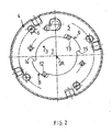
- Fig. 2 a plan view of the disc-shaped lid of the device according to the invention
- Fig. 3 a perspective view of an omega single spring with a schematic representation of the voltage curve along the single spring under load
- Fig. 4 a section along the line AA the Fig. 1 ,
- the Fig. 1 shows the device according to the invention in the assembled state.
- a phaser 2 is pushed onto the free end of the camshaft 1.
- housing bottom 4 of the phase adjuster 2 is located in Fig. 2 shown disc-shaped cover 5, which is fastened by means of screws 6 on the housing bottom 4 of the housing of the phase adjuster 2.
- the disc-shaped cover 5 has a central opening 7, which is located above the opening of the housing bottom 4 in alignment. Through the opening 3 in the housing base 4 to close to the opening 7 in the disc-shaped cover 5 of the Phasenverstellers 2 protrudes the free end of the camshaft 1.
- the opening 7 in the disc-shaped cover 5 has two outwardly directed recesses 8 and 9, which are diametrically opposed to the axis of rotation Since the camshaft 1 are arranged opposite one another and lie on a diameter D2, which is slightly larger than the diameter D1 of the opening 7, so that the opening 7 in the region of the recesses 8 and 9 has a wing-like contour. Close to the outer periphery of the disc-shaped lid 5 are two smaller openings 10 and 11, which are arranged diametrically opposite to the axis of rotation DA.
- blind bores 12 and 13 are introduced into the free end of the camshaft 1 coaxially with the axis of rotation DA (see FIG Fig. 4 ).
- the blind holes 12 and 13 are diametrically opposite and are associated with the respective recesses 8 and 9.
- the blind bore 12 is located in accordance Fig. 1 in the vicinity of the left boundary wall 14 of the recess 8 and the blind bore 13 in the vicinity of the right boundary wall 15 of the recess 9.
- the blind holes 12 and 13 form the anchoring points V1 and V2 for the frictional connection of the later to be described omega single springs 16 with the camshaft 1.
- the smaller openings 10 and 11 in the lid 5 serve as anchoring point V3 and V4 for the frictional connection between the disc-shaped cover 5 and the corresponding omega individual springs 16th As the Fig. 4 Further, the omega single springs 16 are approximately at the level of the disc-shaped lid 5.
- a housing cover 21 the housing of the phaser 2 is closed. This housing cover 21 also secures the installation position of the omega single springs 16.
- omega single spring 16 is shown in perspective with exemplified course of the tensile stresses. It can be seen that the maximum tensile stress of, for example, up to 2000 MPa is in the farthest cross section to the point of introduction of force, ie to the anchoring points V1 and V3.
- the omega single springs 16 are preferably made of round wire spring steel, for example, 2 mm in diameter, but may also have other profile cross-sections, without departing from the invention. They have a long bent end 17, which merges into a rectilinear portion 18, and a short bent end 19. Two of these omega single springs 16 form an omega-spring pair 20, which passes for installation in the device according to the invention.
- the diameter of the omega single springs 16 may be constant or variable over the length of the springs.
- the omega single springs 16 of the omega spring pair 20 are-like Fig.1 shows symmetrically about the axis of rotation DA of the camshaft 1 approximately in the plane of the lid 5 is partially mutually encircling.
- the omega springs 16 are each inserted with their long, bent in the direction of the disc-shaped lid 5 ends 17 in the respective blind holes 12 and 13 of the camshaft 1 and the anchoring point V1 and V2 is by the frictional connection between the long end of the 17th the omega single spring 16 with the camshaft 1 produced (see Fig. 1 ).
- the clamping process ie the Generating the restoring torque described with the device according to the invention.
- the camshaft 1 rotates counterclockwise, for example. With the rotation of the camshaft 1 take the blind holes 12 and 13, the long ends 17 of the omega single spring 16 with.
- the inner disk-shaped cover 5 is fixed to the housing bottom 4 of the phase adjuster 2 and thus also the short ends 19 of the omega individual springs 16 at their 7 anchoring points V3 and V4, so that the omega individual springs 16 between the anchoring points V1 and V3 or V2 and V4 tension and generate depending on the rotational movement of the camshaft, the restoring torque sufficient to bring the unillustrated actuators of the phase adjuster to its original position.
- the clamping operation is accomplished by the adjoining the long end 17 rectilinear portion 18 without voltage spikes by sharp bends in the spring body, because the forces generated by the torque of the camshaft 1 forces are introduced into the spring body approximately in the direction of wire axis FA.
- the omega springs according to the invention are distinguished from the prior art spiral springs by a double maximum tensile stress, a significantly greater resistance to change and a significantly longer service life. At the same time, the omega springs are easily interchangeable and easy to install.
Landscapes
- Engineering & Computer Science (AREA)
- General Engineering & Computer Science (AREA)
- Mechanical Engineering (AREA)
- Valve-Gear Or Valve Arrangements (AREA)
- Valve Device For Special Equipments (AREA)
Claims (7)
- Dispositif de rappel d'un déphaseur d'arbre à cames, comprenant un déphaseur (2) enfilé sur l'extrémité libre d'un arbre à cames (1), déphaseur dans le fond de carter (4) duquel est inséré un couvercle (5) fixé sur le fond de carter (4) et fixe en rotation par rapport à l'arbre à cames, le fond de carter (4) étant pourvu d'une ouverture (3), et comprenant un ressort agissant entre l'arbre à cames et le couvercle pour produire un moment de rappel, caractérisé en ce que l'on prévoit, en tant que ressort, une paire de ressorts en oméga (20) dont les ressorts individuels (16) sont placés de manière symétrique autour de l'axe de rotation (DA) de l'arbre à cames (1) dans le plan du couvercle (5) avec respectivement un point d'attache intérieur (V1, V2) fixé coaxialement par rapport à l'axe de rotation (DA) de l'arbre à cames (1) et un point d'attache (V3, V4) fixé près de la circonférence extérieure du couvercle (5), de manière à ce que, un moment de rappel maximum et une tension de traction maximale des deux ressorts individuels (16) soient appliqués dans la section transversale la plus éloignée entre les points d'attache intérieurs (V1, V2) et les points d'attache extérieurs (V3, V4) lors de la rotation de l'arbre à cames pour rappeler le déphaseur.
- Dispositif selon la revendication 1, caractérisé en ce que le couvercle (5) comporte une ouverture (7) centrale avec des évidements (8, 9) diamétralement opposés pour la mise en tension des ressorts individuels en oméga (16).
- Dispositif selon les revendications 1 et 2, caractérisé en ce que les ressorts individuels en oméga (16) sont placés dans le point d'attache (V1, V2) sur l'arbre à cames (1) avec leurs extrémités réalisées longues (17) et dans le point d'attache (V3, V4) du couvercle (5) avec leurs autres extrémités, courtes (19), les ressorts individuels (16) s'entourant partiellement.
- Dispositif selon la revendication 3, caractérisé en ce que les ressorts en oméga (16) sont formés de manière à ce que l'extrémité longue (17) se poursuive par une section (18) pliée à peu près dans la direction radiale de l'évidement (8, 9) sans courbure brusque, qui introduit les forces produites par le couple de rotation de l'arbre à cames (1) dans les ressorts individuels en oméga (16)dans la direction de l'axe de fil (FA).
- Dispositif selon les revendications 1 à 4, caractérisé en ce que les ressorts individuels en oméga (16) de la paire de ressorts (20) sont de construction identique.
- Dispositif selon les revendications 1 à 5, caractérisé en ce que les ressorts individuels oméga (16) sont en acier à ressorts à section transversale ronde ou en fil d'acier à ressorts quadrangulaire à arêtes arrondies, ou ont un profil en U.
- Dispositif selon la revendication 6, caractérisé en ce que les ressorts individuels en oméga (16) ont un diamètre constant ou variable sur leur longueur.
Priority Applications (3)
| Application Number | Priority Date | Filing Date | Title |
|---|---|---|---|
| EP08021879A EP2199548B1 (fr) | 2008-12-17 | 2008-12-17 | Dispositif de rappel d'un déphaseur pour un arbre à came |
| AT08021879T ATE497572T1 (de) | 2008-12-17 | 2008-12-17 | Einrichtung zum rückstellen eines phasenverstellers für eine nockenwelle |
| DE502008002536T DE502008002536D1 (de) | 2008-12-17 | 2008-12-17 | Einrichtung zum Rückstellen eines Phasenverstellers für eine Nockenwelle |
Applications Claiming Priority (1)
| Application Number | Priority Date | Filing Date | Title |
|---|---|---|---|
| EP08021879A EP2199548B1 (fr) | 2008-12-17 | 2008-12-17 | Dispositif de rappel d'un déphaseur pour un arbre à came |
Publications (2)
| Publication Number | Publication Date |
|---|---|
| EP2199548A1 EP2199548A1 (fr) | 2010-06-23 |
| EP2199548B1 true EP2199548B1 (fr) | 2011-02-02 |
Family
ID=40638003
Family Applications (1)
| Application Number | Title | Priority Date | Filing Date |
|---|---|---|---|
| EP08021879A Active EP2199548B1 (fr) | 2008-12-17 | 2008-12-17 | Dispositif de rappel d'un déphaseur pour un arbre à came |
Country Status (3)
| Country | Link |
|---|---|
| EP (1) | EP2199548B1 (fr) |
| AT (1) | ATE497572T1 (fr) |
| DE (1) | DE502008002536D1 (fr) |
Cited By (1)
| Publication number | Priority date | Publication date | Assignee | Title |
|---|---|---|---|---|
| DE102015217261B3 (de) * | 2015-09-10 | 2016-12-15 | Schaeffler Technologies AG & Co. KG | Nockenwellenversteller mit einer Feder |
Families Citing this family (1)
| Publication number | Priority date | Publication date | Assignee | Title |
|---|---|---|---|---|
| DE102015205162A1 (de) * | 2015-03-23 | 2016-03-31 | Schaeffler Technologies AG & Co. KG | Nockenwellenversteller |
Family Cites Families (9)
| Publication number | Priority date | Publication date | Assignee | Title |
|---|---|---|---|---|
| US4423296A (en) * | 1982-02-18 | 1983-12-27 | Rca Corporation | Shock and vibration resistant electrical switch |
| JP3846605B2 (ja) * | 1997-10-30 | 2006-11-15 | アイシン精機株式会社 | 弁開閉時期制御装置 |
| US6276321B1 (en) * | 2000-01-11 | 2001-08-21 | Delphi Technologies, Inc. | Cam phaser having a torsional bias spring to offset retarding force of camshaft friction |
| JP4304878B2 (ja) * | 2001-03-30 | 2009-07-29 | 株式会社デンソー | バルブタイミング調整装置 |
| US6948467B2 (en) | 2004-02-27 | 2005-09-27 | Delphi Technologies, Inc. | Locking pin mechanism for a vane-type cam phaser |
| DE102004061710A1 (de) | 2004-12-22 | 2006-07-06 | Daimlerchrysler Ag | Nockenwellenverstelleinrichtung |
| DE102006009192A1 (de) | 2006-02-28 | 2007-09-06 | Daimlerchrysler Ag | Verstelleinrichtung für eine Brennkraftmaschine |
| DE102006022219B4 (de) * | 2006-05-11 | 2008-01-03 | Hydraulik-Ring Gmbh | Leckagedichter Nockenwellenversteller mit Rückstellfeder |
| DE102007019920A1 (de) | 2007-04-27 | 2008-11-06 | Schaeffler Kg | Verrieglungs- und Drehwinkelbegrenzungsanordnung eines Nockenwellenverstellers |
-
2008
- 2008-12-17 EP EP08021879A patent/EP2199548B1/fr active Active
- 2008-12-17 AT AT08021879T patent/ATE497572T1/de active
- 2008-12-17 DE DE502008002536T patent/DE502008002536D1/de active Active
Cited By (1)
| Publication number | Priority date | Publication date | Assignee | Title |
|---|---|---|---|---|
| DE102015217261B3 (de) * | 2015-09-10 | 2016-12-15 | Schaeffler Technologies AG & Co. KG | Nockenwellenversteller mit einer Feder |
Also Published As
| Publication number | Publication date |
|---|---|
| ATE497572T1 (de) | 2011-02-15 |
| DE502008002536D1 (de) | 2011-03-17 |
| EP2199548A1 (fr) | 2010-06-23 |
Similar Documents
| Publication | Publication Date | Title |
|---|---|---|
| DE102009054049B4 (de) | Nockenwellenverstellanordnung | |
| EP2638255B1 (fr) | Déphaseur d'arbre a cames pour moteur a combustion interne | |
| EP2739830B1 (fr) | Commande de soupape d'un moteur à combustion interne, moteur à combustion interne et procédé de fabrication d'une commande de soupape correspondante | |
| EP2102454A1 (fr) | Poussoir bloqué en rotation d'un mécanisme de commande de soupapes | |
| WO2012013386A1 (fr) | Clapet anti-retour et vanne hydraulique avec un clapet anti-retour intégré | |
| DE3429424A1 (de) | Tragsaeule | |
| DE102009051310A1 (de) | Befestigungsanordnung eines Nockenwellenverstellers | |
| DE10351223B4 (de) | Nockenwellenverstelleinrichtung für Fahrzeuge, vorzugsweise für Kraftfahrzeuge | |
| WO2012104242A1 (fr) | Dispositif destiné à modifier la position angulaire relative d' un arbre à cames par rapport au vilebrequin d'un moteur à combustion interne | |
| EP3146166A1 (fr) | Arbre à cames | |
| DE102011113669A1 (de) | Elektrische Lenkverriegelung | |
| DE10105807C1 (de) | Kipphebel für einen Ventiltrieb eines Verbrennungsmotors mit Vorrichtung zur selbsttätigen Ein-/Nachstellung des Ventilspiels | |
| EP2199548A1 (fr) | Dispositif de rappel d'un déphaseur pour un arbre à came | |
| EP1106817A2 (fr) | Soupape à géométrie de butée améliorée | |
| EP3158173B1 (fr) | Déphaseur à moteur oscillant pour arbre à cames | |
| DE102009038662B4 (de) | Ventiltrieb einer Brennkraftmaschine | |
| DE102008034070A1 (de) | Schließzylinder mit federkraftunterstützter Zylinderkernrückstellung | |
| DE102005020529A1 (de) | Nockenwellenversteller | |
| EP3073072B1 (fr) | Commande de soupape à commande mécanique et système de commande de soupape pouvant être commandé | |
| DE19728348C2 (de) | Vorrichtung für eine elektromagnetische Ventilsteuerung | |
| DE19928284A1 (de) | Ventiltrieb für Verbrennungskraftmaschine | |
| DE102013104642A1 (de) | Elektromagnetische Stellvorrichtung, Verwendung einer solchen elektromagnetischen Stellvorrichtung und System aufweisend eine solche elektromagnetische Stellvorrichtung | |
| DE102009034787A1 (de) | Vorrichtung zur Veränderung der relativen Winkellage einer Nockenwelle gegenüber einer Kurbelwelle einer Brennkraftmaschine | |
| EP1124040A1 (fr) | Actionneur électromagnétique pour soupape | |
| DE102008062184A1 (de) | Vorrichtung zum Einstellen der relativen Drehlage einer Nockenwelle einer Brennkraftmaschine zu einer die Nockenwelle antreibenden Kurbelwelle |
Legal Events
| Date | Code | Title | Description |
|---|---|---|---|
| PUAI | Public reference made under article 153(3) epc to a published international application that has entered the european phase |
Free format text: ORIGINAL CODE: 0009012 |
|
| AK | Designated contracting states |
Kind code of ref document: A1 Designated state(s): AT BE BG CH CY CZ DE DK EE ES FI FR GB GR HR HU IE IS IT LI LT LU LV MC MT NL NO PL PT RO SE SI SK TR |
|
| AX | Request for extension of the european patent |
Extension state: AL BA MK RS |
|
| 17P | Request for examination filed |
Effective date: 20100702 |
|
| GRAP | Despatch of communication of intention to grant a patent |
Free format text: ORIGINAL CODE: EPIDOSNIGR1 |
|
| GRAS | Grant fee paid |
Free format text: ORIGINAL CODE: EPIDOSNIGR3 |
|
| GRAA | (expected) grant |
Free format text: ORIGINAL CODE: 0009210 |
|
| AK | Designated contracting states |
Kind code of ref document: B1 Designated state(s): AT BE BG CH CY CZ DE DK EE ES FI FR GB GR HR HU IE IS IT LI LT LU LV MC MT NL NO PL PT RO SE SI SK TR |
|
| REG | Reference to a national code |
Ref country code: GB Ref legal event code: FG4D Free format text: NOT ENGLISH |
|
| REG | Reference to a national code |
Ref country code: CH Ref legal event code: EP |
|
| AKX | Designation fees paid |
Designated state(s): AT BE BG CH CY CZ DE DK EE ES FI FR GB GR HR HU IE IS IT LI LT LU LV MC MT NL NO PL PT RO SE SI SK TR |
|
| REG | Reference to a national code |
Ref country code: IE Ref legal event code: FG4D Free format text: LANGUAGE OF EP DOCUMENT: GERMAN |
|
| REF | Corresponds to: |
Ref document number: 502008002536 Country of ref document: DE Date of ref document: 20110317 Kind code of ref document: P |
|
| REG | Reference to a national code |
Ref country code: DE Ref legal event code: R096 Ref document number: 502008002536 Country of ref document: DE Effective date: 20110317 |
|
| REG | Reference to a national code |
Ref country code: CH Ref legal event code: NV Representative=s name: BOVARD AG |
|
| REG | Reference to a national code |
Ref country code: NL Ref legal event code: VDEP Effective date: 20110202 |
|
| LTIE | Lt: invalidation of european patent or patent extension |
Effective date: 20110202 |
|
| PG25 | Lapsed in a contracting state [announced via postgrant information from national office to epo] |
Ref country code: LT Free format text: LAPSE BECAUSE OF FAILURE TO SUBMIT A TRANSLATION OF THE DESCRIPTION OR TO PAY THE FEE WITHIN THE PRESCRIBED TIME-LIMIT Effective date: 20110202 Ref country code: LV Free format text: LAPSE BECAUSE OF FAILURE TO SUBMIT A TRANSLATION OF THE DESCRIPTION OR TO PAY THE FEE WITHIN THE PRESCRIBED TIME-LIMIT Effective date: 20110202 Ref country code: SE Free format text: LAPSE BECAUSE OF FAILURE TO SUBMIT A TRANSLATION OF THE DESCRIPTION OR TO PAY THE FEE WITHIN THE PRESCRIBED TIME-LIMIT Effective date: 20110202 Ref country code: IS Free format text: LAPSE BECAUSE OF FAILURE TO SUBMIT A TRANSLATION OF THE DESCRIPTION OR TO PAY THE FEE WITHIN THE PRESCRIBED TIME-LIMIT Effective date: 20110602 Ref country code: GR Free format text: LAPSE BECAUSE OF FAILURE TO SUBMIT A TRANSLATION OF THE DESCRIPTION OR TO PAY THE FEE WITHIN THE PRESCRIBED TIME-LIMIT Effective date: 20110503 Ref country code: ES Free format text: LAPSE BECAUSE OF FAILURE TO SUBMIT A TRANSLATION OF THE DESCRIPTION OR TO PAY THE FEE WITHIN THE PRESCRIBED TIME-LIMIT Effective date: 20110513 Ref country code: PT Free format text: LAPSE BECAUSE OF FAILURE TO SUBMIT A TRANSLATION OF THE DESCRIPTION OR TO PAY THE FEE WITHIN THE PRESCRIBED TIME-LIMIT Effective date: 20110602 Ref country code: NO Free format text: LAPSE BECAUSE OF FAILURE TO SUBMIT A TRANSLATION OF THE DESCRIPTION OR TO PAY THE FEE WITHIN THE PRESCRIBED TIME-LIMIT Effective date: 20110502 Ref country code: HR Free format text: LAPSE BECAUSE OF FAILURE TO SUBMIT A TRANSLATION OF THE DESCRIPTION OR TO PAY THE FEE WITHIN THE PRESCRIBED TIME-LIMIT Effective date: 20110202 |
|
| PG25 | Lapsed in a contracting state [announced via postgrant information from national office to epo] |
Ref country code: SI Free format text: LAPSE BECAUSE OF FAILURE TO SUBMIT A TRANSLATION OF THE DESCRIPTION OR TO PAY THE FEE WITHIN THE PRESCRIBED TIME-LIMIT Effective date: 20110202 Ref country code: BG Free format text: LAPSE BECAUSE OF FAILURE TO SUBMIT A TRANSLATION OF THE DESCRIPTION OR TO PAY THE FEE WITHIN THE PRESCRIBED TIME-LIMIT Effective date: 20110502 Ref country code: FI Free format text: LAPSE BECAUSE OF FAILURE TO SUBMIT A TRANSLATION OF THE DESCRIPTION OR TO PAY THE FEE WITHIN THE PRESCRIBED TIME-LIMIT Effective date: 20110202 Ref country code: PL Free format text: LAPSE BECAUSE OF FAILURE TO SUBMIT A TRANSLATION OF THE DESCRIPTION OR TO PAY THE FEE WITHIN THE PRESCRIBED TIME-LIMIT Effective date: 20110202 Ref country code: CY Free format text: LAPSE BECAUSE OF FAILURE TO SUBMIT A TRANSLATION OF THE DESCRIPTION OR TO PAY THE FEE WITHIN THE PRESCRIBED TIME-LIMIT Effective date: 20110202 Ref country code: NL Free format text: LAPSE BECAUSE OF FAILURE TO SUBMIT A TRANSLATION OF THE DESCRIPTION OR TO PAY THE FEE WITHIN THE PRESCRIBED TIME-LIMIT Effective date: 20110202 |
|
| REG | Reference to a national code |
Ref country code: IE Ref legal event code: FD4D |
|
| PG25 | Lapsed in a contracting state [announced via postgrant information from national office to epo] |
Ref country code: EE Free format text: LAPSE BECAUSE OF FAILURE TO SUBMIT A TRANSLATION OF THE DESCRIPTION OR TO PAY THE FEE WITHIN THE PRESCRIBED TIME-LIMIT Effective date: 20110202 Ref country code: IE Free format text: LAPSE BECAUSE OF FAILURE TO SUBMIT A TRANSLATION OF THE DESCRIPTION OR TO PAY THE FEE WITHIN THE PRESCRIBED TIME-LIMIT Effective date: 20110202 Ref country code: DK Free format text: LAPSE BECAUSE OF FAILURE TO SUBMIT A TRANSLATION OF THE DESCRIPTION OR TO PAY THE FEE WITHIN THE PRESCRIBED TIME-LIMIT Effective date: 20110202 |
|
| PG25 | Lapsed in a contracting state [announced via postgrant information from national office to epo] |
Ref country code: RO Free format text: LAPSE BECAUSE OF FAILURE TO SUBMIT A TRANSLATION OF THE DESCRIPTION OR TO PAY THE FEE WITHIN THE PRESCRIBED TIME-LIMIT Effective date: 20110202 Ref country code: CZ Free format text: LAPSE BECAUSE OF FAILURE TO SUBMIT A TRANSLATION OF THE DESCRIPTION OR TO PAY THE FEE WITHIN THE PRESCRIBED TIME-LIMIT Effective date: 20110202 Ref country code: SK Free format text: LAPSE BECAUSE OF FAILURE TO SUBMIT A TRANSLATION OF THE DESCRIPTION OR TO PAY THE FEE WITHIN THE PRESCRIBED TIME-LIMIT Effective date: 20110202 |
|
| PLBE | No opposition filed within time limit |
Free format text: ORIGINAL CODE: 0009261 |
|
| STAA | Information on the status of an ep patent application or granted ep patent |
Free format text: STATUS: NO OPPOSITION FILED WITHIN TIME LIMIT |
|
| 26N | No opposition filed |
Effective date: 20111103 |
|
| REG | Reference to a national code |
Ref country code: DE Ref legal event code: R097 Ref document number: 502008002536 Country of ref document: DE Effective date: 20111103 |
|
| PG25 | Lapsed in a contracting state [announced via postgrant information from national office to epo] |
Ref country code: IT Free format text: LAPSE BECAUSE OF FAILURE TO SUBMIT A TRANSLATION OF THE DESCRIPTION OR TO PAY THE FEE WITHIN THE PRESCRIBED TIME-LIMIT Effective date: 20110202 |
|
| BERE | Be: lapsed |
Owner name: FEINTOOL INTELLECTUAL PROPERTY A.G. Effective date: 20111231 |
|
| PG25 | Lapsed in a contracting state [announced via postgrant information from national office to epo] |
Ref country code: MC Free format text: LAPSE BECAUSE OF NON-PAYMENT OF DUE FEES Effective date: 20111231 |
|
| REG | Reference to a national code |
Ref country code: FR Ref legal event code: ST Effective date: 20120831 |
|
| PG25 | Lapsed in a contracting state [announced via postgrant information from national office to epo] |
Ref country code: BE Free format text: LAPSE BECAUSE OF NON-PAYMENT OF DUE FEES Effective date: 20111231 |
|
| PG25 | Lapsed in a contracting state [announced via postgrant information from national office to epo] |
Ref country code: MT Free format text: LAPSE BECAUSE OF FAILURE TO SUBMIT A TRANSLATION OF THE DESCRIPTION OR TO PAY THE FEE WITHIN THE PRESCRIBED TIME-LIMIT Effective date: 20110202 |
|
| PG25 | Lapsed in a contracting state [announced via postgrant information from national office to epo] |
Ref country code: FR Free format text: LAPSE BECAUSE OF NON-PAYMENT OF DUE FEES Effective date: 20120102 |
|
| PG25 | Lapsed in a contracting state [announced via postgrant information from national office to epo] |
Ref country code: LU Free format text: LAPSE BECAUSE OF NON-PAYMENT OF DUE FEES Effective date: 20111217 |
|
| GBPC | Gb: european patent ceased through non-payment of renewal fee |
Effective date: 20121217 |
|
| PG25 | Lapsed in a contracting state [announced via postgrant information from national office to epo] |
Ref country code: TR Free format text: LAPSE BECAUSE OF FAILURE TO SUBMIT A TRANSLATION OF THE DESCRIPTION OR TO PAY THE FEE WITHIN THE PRESCRIBED TIME-LIMIT Effective date: 20110202 |
|
| PG25 | Lapsed in a contracting state [announced via postgrant information from national office to epo] |
Ref country code: HU Free format text: LAPSE BECAUSE OF FAILURE TO SUBMIT A TRANSLATION OF THE DESCRIPTION OR TO PAY THE FEE WITHIN THE PRESCRIBED TIME-LIMIT Effective date: 20110202 |
|
| REG | Reference to a national code |
Ref country code: CH Ref legal event code: PUE Owner name: FEINTOOL INTERNATIONAL HOLDING AG, CH Free format text: FORMER OWNER: FEINTOOL INTELLECTUAL PROPERTY AG, CH |
|
| PG25 | Lapsed in a contracting state [announced via postgrant information from national office to epo] |
Ref country code: GB Free format text: LAPSE BECAUSE OF NON-PAYMENT OF DUE FEES Effective date: 20121217 |
|
| REG | Reference to a national code |
Ref country code: DE Ref legal event code: R082 Ref document number: 502008002536 Country of ref document: DE Representative=s name: COHAUSZ HANNIG BORKOWSKI WISSGOTT, DE |
|
| REG | Reference to a national code |
Ref country code: DE Ref legal event code: R082 Ref document number: 502008002536 Country of ref document: DE Representative=s name: COHAUSZ HANNIG BORKOWSKI WISSGOTT, DE Effective date: 20140212 Ref country code: DE Ref legal event code: R081 Ref document number: 502008002536 Country of ref document: DE Owner name: FEINTOOL INTERNATIONAL HOLDING AG, CH Free format text: FORMER OWNER: FEINTOOL INTELLECTUAL PROPERTY AG, LYSS, CH Effective date: 20140212 |
|
| REG | Reference to a national code |
Ref country code: AT Ref legal event code: MM01 Ref document number: 497572 Country of ref document: AT Kind code of ref document: T Effective date: 20131217 |
|
| PG25 | Lapsed in a contracting state [announced via postgrant information from national office to epo] |
Ref country code: AT Free format text: LAPSE BECAUSE OF NON-PAYMENT OF DUE FEES Effective date: 20131217 |
|
| REG | Reference to a national code |
Ref country code: CH Ref legal event code: U11 Free format text: ST27 STATUS EVENT CODE: U-0-0-U10-U11 (AS PROVIDED BY THE NATIONAL OFFICE) Effective date: 20260101 |
|
| PGFP | Annual fee paid to national office [announced via postgrant information from national office to epo] |
Ref country code: DE Payment date: 20251222 Year of fee payment: 18 |
|
| PGFP | Annual fee paid to national office [announced via postgrant information from national office to epo] |
Ref country code: CH Payment date: 20260101 Year of fee payment: 18 |