EP1124065B1 - Ecrou de blocage - Google Patents
Ecrou de blocage Download PDFInfo
- Publication number
- EP1124065B1 EP1124065B1 EP01850025A EP01850025A EP1124065B1 EP 1124065 B1 EP1124065 B1 EP 1124065B1 EP 01850025 A EP01850025 A EP 01850025A EP 01850025 A EP01850025 A EP 01850025A EP 1124065 B1 EP1124065 B1 EP 1124065B1
- Authority
- EP
- European Patent Office
- Prior art keywords
- locking pin
- bore
- locking
- lock nut
- oblique
- Prior art date
- Legal status (The legal status is an assumption and is not a legal conclusion. Google has not performed a legal analysis and makes no representation as to the accuracy of the status listed.)
- Expired - Lifetime
Links
- 239000000463 material Substances 0.000 claims description 4
- 239000000314 lubricant Substances 0.000 claims description 3
- 229910000831 Steel Inorganic materials 0.000 claims description 2
- 239000010959 steel Substances 0.000 claims description 2
- 229910001369 Brass Inorganic materials 0.000 description 4
- 239000010951 brass Substances 0.000 description 4
- 238000005520 cutting process Methods 0.000 description 4
- 230000000694 effects Effects 0.000 description 4
- 230000015572 biosynthetic process Effects 0.000 description 3
- 238000003754 machining Methods 0.000 description 2
- 230000000295 complement effect Effects 0.000 description 1
- 238000005470 impregnation Methods 0.000 description 1
- 230000037431 insertion Effects 0.000 description 1
- 238000003780 insertion Methods 0.000 description 1
- 238000004519 manufacturing process Methods 0.000 description 1
- 230000000717 retained effect Effects 0.000 description 1
Images
Classifications
-
- F—MECHANICAL ENGINEERING; LIGHTING; HEATING; WEAPONS; BLASTING
- F16—ENGINEERING ELEMENTS AND UNITS; GENERAL MEASURES FOR PRODUCING AND MAINTAINING EFFECTIVE FUNCTIONING OF MACHINES OR INSTALLATIONS; THERMAL INSULATION IN GENERAL
- F16B—DEVICES FOR FASTENING OR SECURING CONSTRUCTIONAL ELEMENTS OR MACHINE PARTS TOGETHER, e.g. NAILS, BOLTS, CIRCLIPS, CLAMPS, CLIPS OR WEDGES; JOINTS OR JOINTING
- F16B39/00—Locking of screws, bolts or nuts
- F16B39/02—Locking of screws, bolts or nuts in which the locking takes place after screwing down
- F16B39/04—Locking of screws, bolts or nuts in which the locking takes place after screwing down with a member penetrating the screw-threaded surface of at least one part, e.g. a pin, a wedge, cotter-pin, screw
-
- Y—GENERAL TAGGING OF NEW TECHNOLOGICAL DEVELOPMENTS; GENERAL TAGGING OF CROSS-SECTIONAL TECHNOLOGIES SPANNING OVER SEVERAL SECTIONS OF THE IPC; TECHNICAL SUBJECTS COVERED BY FORMER USPC CROSS-REFERENCE ART COLLECTIONS [XRACs] AND DIGESTS
- Y10—TECHNICAL SUBJECTS COVERED BY FORMER USPC
- Y10S—TECHNICAL SUBJECTS COVERED BY FORMER USPC CROSS-REFERENCE ART COLLECTIONS [XRACs] AND DIGESTS
- Y10S411/00—Expanded, threaded, driven, headed, tool-deformed, or locked-threaded fastener
- Y10S411/924—Coupled nut and bolt
- Y10S411/929—Thread lock
- Y10S411/941—Side clutch
Definitions
- the present invention refers to a lock nut of the type having a threaded main bore for receiving a threaded portion, which lock nut has a number of oblique bores in each of which is inserted a locking pin for engagement with its forward end against the threaded portion, the oblique bore and the associated locking pin having common longitudinal axis extending at substantially the same angle to the axis of the threaded main bore as one of the flanks of the thread of said threaded main bore, whereby the forward end of the lock nut thereby having at least one flank substantially parallel to said longitudinal axis and which can lie substantially parallel to the portions of said one flank of said threaded main bore adjacent the inner end of the oblique bore.
- Such lock nuts are earlier known, i.e. by GB 1 561 946 A, and their purpose has been to provide a lock nut with substantially the same locking effect even after repeated use.
- Each locking pin thereby has been shaped as a cylindrical dowel, having a smooth envelope surface and the locking pin was manufactured from brass.
- the locking faces of the pins and the thread of the main bore are machined in the same machining operation, that is the pins are inserted in their respective oblique bores with the forward end of each locking pin projecting into the not yet threaded main bore of the lock nut.
- This lock nut thereupon is clamped in a clamping device and is subjected to thread cutting, whereby also the forward ends of the locking pins are cut to form at least one flank each.
- each locking pin is tightened against the threaded portion by means of a grub screw or the like.
- the locking faces of the pins are pressed against the thread flanks of the threaded portion, thereby giving a locking effect provided entirely by friction forces, thereby avoiding deformation of the locking pin.
- each pin fits very snugly into its bore, which means that the fitting of the pins in their respective oblique bores in the lock nut is difficult, and the material of the pin seizes against the inner envelope surface of the oblique bore.
- the purpose of the present invention is to provide an improvement of the known lock nut, thus that the problems mentioned are reduced or even eliminated, and this is achieved in that the lock nut has been given the features defined in the accompanying claims.
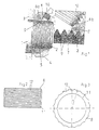
- Fig. 1 a shaft 1 with a threaded portion 2, and with a machine member 3, which is locked to the shaft 1 by means of a lock nut 4 according to the invention.
- the lock nut 4 has an internal main bore with a thread 5 complementary to the external thread of the threaded portion 2.
- a number of evenly spaced through bores 6 projecting from the outside of the lock nut to the main bore thereof. These bores 6 are oblique and have an inclination thus that its longitudinal axis is substantially parallel to one flank 7 of the thread in the threaded portion 2.
- Each oblique bore 6 has a first portion 6a being smooth and being located at the inner part of the bore, and a second, outer portion 6b, which is threaded.
- each oblique bore 6 is inserted a substantially cylindrical locking pin 8.
- the inclination of the bore 6 causes the locking pin 8 to have its side wall coinciding with one flank of the thread in the threaded portion 2.
- Fig 2 shows the locking pin 8 in planar side view
- Fig. 3 shows the same locking pin 8 in an end view.
- the locking pin 8 here is shown before it has been machined during the thread cutting operation for the interior thread of the lock nut 4 and as can be seen the basic form is substantially a cylinder, having chamfered end portions 11, and not a smooth outer envelope surface but a number of axially extending circumferentially arranged grooves or serrations 12, evenly spaced along the circumference.
- This locking pin 8 is further not made from brass or the like but is manufactured from sintered steel, which is preferably soaked with a lubricant at manufacture.
- Such a locking pin 8 can be inserted in its oblique bore much easier than the earlier used brass pin with its smooth external surface, due to the fact that the friction is reduced substantially as the contact between the locking pin 8 and its bore is not over the entire surface but just over the outer line areas of the serrated surface.
- the impregnation with lubricant of the sinter material locking pin further will help to reduce the friction between the locking pin 8 and its bore 6a, thereby facilitating insertion of the pin in position.
- the ridges of the serration 12 furthermore will prevent the pin from rotating in the bore, thereby securing that it is in correct position during and after cutting of the thread formation.
- the lock nut 4 has preferably three evenly spaced apart oblique bores with associated locking pins 8.
Landscapes
- Engineering & Computer Science (AREA)
- General Engineering & Computer Science (AREA)
- Mechanical Engineering (AREA)
- Bolts, Nuts, And Washers (AREA)
- Snaps, Bayonet Connections, Set Pins, And Snap Rings (AREA)
- Cutting Tools, Boring Holders, And Turrets (AREA)
Claims (3)
- Ecrou de blocage (4) ayant un trou principal fileté pour recevoir une partie filetée (2), lequel écrou de blocage comporte un certain nombre de trous obliques (6) où est inséré, dans chacun d'entre eux, un axe de blocage (8) destiné à se mettre en prise à l'aide de son extrémité avant contre la partie filetée (2), le trou oblique (6) et l'axe de blocage associé (8) ayant un axe longitudinal commun s'étendant en formant sensiblement le même angle par rapport à l'axe du trou principal fileté en tant que l'un des flancs (7) du filetage dudit trou principal fileté, grâce à quoi l'extrémité avant de l'écrou de blocage ayant ainsi au moins un flanc (9) sensiblement parallèle audit axe longitudinal et qui peut être sensiblement parallèle aux parties dudit flanc (7) dudit trou principal fileté en une position adjacente à l'extrémité intérieure du trou oblique,
caractérisé en ce que l'axe de blocage (8) est un corps sensiblement cylindrique comportant le long de sa surface d'enveloppe une pluralité de dentelures ou rainures (12) s'étendant axialement et régulièrement espacées qui facilitent l'introduction de l'axe (8) dans son trou associé (6). - Ecrou de blocage selon la revendication 1, caractérisé en ce que l'axe de blocage (8) est fait à partir d'un matériau fritté, de préférence de l'acier.
- Ecrou de blocage selon la revendication 2, caractérisé en ce que le matériau de l'axe de blocage fritté (8) est imprégné d'un lubrifiant réduisant les frottements.
Applications Claiming Priority (2)
| Application Number | Priority Date | Filing Date | Title |
|---|---|---|---|
| JP2000033133 | 2000-02-10 | ||
| JP2000033133A JP3278114B2 (ja) | 2000-02-10 | 2000-02-10 | ロックナット |
Publications (2)
| Publication Number | Publication Date |
|---|---|
| EP1124065A1 EP1124065A1 (fr) | 2001-08-16 |
| EP1124065B1 true EP1124065B1 (fr) | 2004-05-12 |
Family
ID=18557652
Family Applications (1)
| Application Number | Title | Priority Date | Filing Date |
|---|---|---|---|
| EP01850025A Expired - Lifetime EP1124065B1 (fr) | 2000-02-10 | 2001-02-02 | Ecrou de blocage |
Country Status (5)
| Country | Link |
|---|---|
| US (1) | US6428257B2 (fr) |
| EP (1) | EP1124065B1 (fr) |
| JP (1) | JP3278114B2 (fr) |
| CN (1) | CN1272554C (fr) |
| DE (1) | DE60103187T2 (fr) |
Families Citing this family (15)
| Publication number | Priority date | Publication date | Assignee | Title |
|---|---|---|---|---|
| EP1279544A3 (fr) | 2001-07-23 | 2003-10-29 | Nissan Motor Co., Ltd. | Chaíne motrice hybride pour véhicules |
| JP3578451B2 (ja) | 2001-07-23 | 2004-10-20 | 日産自動車株式会社 | 駆動装置 |
| DE60216373T2 (de) | 2001-07-23 | 2007-03-15 | Nissan Motor Co., Ltd., Yokohama | Hybridantriebsstrang eines Kraftfahrzeugs |
| GB2417367A (en) * | 2004-08-19 | 2006-02-22 | Richard Henry Pearce | Electrical earthing nut |
| US20090087280A1 (en) * | 2007-10-01 | 2009-04-02 | Harnetiaux Travis L | Reuseable lock nut device |
| TWI452210B (zh) * | 2010-12-09 | 2014-09-11 | Yinsh Prec Ind Co Ltd | 多向全方位鎖制之精密螺帽 |
| TWI461610B (zh) * | 2010-12-17 | 2014-11-21 | Yinsh Prec Ind Co Ltd | 複合鎖制之精密螺帽 |
| JP5254397B2 (ja) * | 2010-12-09 | 2013-08-07 | 盈錫精密工業股▲ふん▼有限公司 | 多数パターンを有すロックシステムの精密ナット |
| CN102560045B (zh) * | 2010-12-22 | 2014-10-01 | 中国科学院金属研究所 | 块体纳米结构低碳钢及其制备方法 |
| CN102606601A (zh) * | 2011-01-19 | 2012-07-25 | 盈锡精密工业股份有限公司 | 锁制精密螺帽 |
| CN102352883A (zh) * | 2011-09-29 | 2012-02-15 | 山西潞安集团司马煤业有限公司 | 一种螺母 |
| DE102012103921A1 (de) * | 2012-05-04 | 2013-11-07 | De-Sta-Co Europe Gmbh | Spannvorrichtung |
| CN103541606B (zh) * | 2012-07-09 | 2016-05-04 | 山西全安新技术开发有限公司 | 一种用来锁紧螺杆的两防锁装置及其锁紧螺杆的方法 |
| US20150147113A1 (en) * | 2013-11-26 | 2015-05-28 | II Phillip C. Crabtree | Frameless furniture system |
| CN121047838A (zh) * | 2025-10-09 | 2025-12-02 | 中国船舶集团有限公司第七一一研究所 | 压缩机、lng船液货系统及压缩机安装方法 |
Family Cites Families (3)
| Publication number | Priority date | Publication date | Assignee | Title |
|---|---|---|---|---|
| US2251202A (en) * | 1938-01-06 | 1941-07-29 | Holo Krome Screw Corp | Drive pin |
| SE411245B (sv) | 1976-12-02 | 1979-12-10 | Idea Ab | Tapplasmutter |
| JPS6012791Y2 (ja) * | 1981-07-20 | 1985-04-24 | マエダ工業株式会社 | 自転車のヘツドセツト用袋ナツト |
-
2000
- 2000-02-10 JP JP2000033133A patent/JP3278114B2/ja not_active Expired - Lifetime
-
2001
- 2001-02-02 EP EP01850025A patent/EP1124065B1/fr not_active Expired - Lifetime
- 2001-02-02 DE DE60103187T patent/DE60103187T2/de not_active Expired - Lifetime
- 2001-02-07 CN CNB011032219A patent/CN1272554C/zh not_active Expired - Lifetime
- 2001-02-09 US US09/779,569 patent/US6428257B2/en not_active Expired - Lifetime
Also Published As
| Publication number | Publication date |
|---|---|
| DE60103187T2 (de) | 2005-07-07 |
| JP3278114B2 (ja) | 2002-04-30 |
| US20010026745A1 (en) | 2001-10-04 |
| US6428257B2 (en) | 2002-08-06 |
| CN1272554C (zh) | 2006-08-30 |
| CN1308192A (zh) | 2001-08-15 |
| EP1124065A1 (fr) | 2001-08-16 |
| JP2001221222A (ja) | 2001-08-17 |
| DE60103187D1 (de) | 2004-06-17 |
Similar Documents
| Publication | Publication Date | Title |
|---|---|---|
| EP1124065A1 (fr) | Ecrou de blocage | |
| US4684284A (en) | Anti-rotation lock assembly | |
| RU2666655C2 (ru) | Патрон | |
| US4481702A (en) | Method of assembling threaded insert bushing within a working material | |
| US3738691A (en) | Split contractible bushing | |
| US2645513A (en) | Cylinder construction | |
| KR100639803B1 (ko) | 밀링 툴 | |
| EP2944407A1 (fr) | Agencement de fixation ainsi qu'une pièce interchangeable et une clé de verrouillage | |
| US2830635A (en) | Self-locking set screw having frangible intermediate portion | |
| EP0473581A1 (fr) | Cheville. | |
| JP2002531283A (ja) | 切削ロータを備えたペレット製造装置 | |
| US3378285A (en) | Keying device | |
| EP0251016B1 (fr) | Dispositif de montage avec douille de serrage | |
| US4190388A (en) | Single-point cutting tool | |
| US8690491B2 (en) | Rotary cutting tool | |
| US4991993A (en) | Lock coupling | |
| US4349955A (en) | Method of locking a male member to a female member | |
| WO2023006406A1 (fr) | Raccord de tige filetée à surfaces de contact sans filetage | |
| US2395288A (en) | Inserted blade cutter | |
| US3414034A (en) | Lock ring for threaded members | |
| US3851977A (en) | Shaft mountings for pulleys, sprockets, coupling flanges and other machine elements | |
| JPH04228912A (ja) | 締着具 | |
| US9364941B2 (en) | Male threaded pipe fitting extraction device | |
| WO2013164263A1 (fr) | Fixation axiale pour outils rotatifs | |
| US3987525A (en) | Rotary cutter |
Legal Events
| Date | Code | Title | Description |
|---|---|---|---|
| PUAI | Public reference made under article 153(3) epc to a published international application that has entered the european phase |
Free format text: ORIGINAL CODE: 0009012 |
|
| AK | Designated contracting states |
Kind code of ref document: A1 Designated state(s): DE FR GB IT SE |
|
| AX | Request for extension of the european patent |
Free format text: AL;LT;LV;MK;RO;SI |
|
| 17P | Request for examination filed |
Effective date: 20020218 |
|
| AKX | Designation fees paid |
Free format text: DE FR GB IT SE |
|
| GRAP | Despatch of communication of intention to grant a patent |
Free format text: ORIGINAL CODE: EPIDOSNIGR1 |
|
| RTI1 | Title (correction) |
Free format text: LOCK NUT |
|
| GRAS | Grant fee paid |
Free format text: ORIGINAL CODE: EPIDOSNIGR3 |
|
| GRAA | (expected) grant |
Free format text: ORIGINAL CODE: 0009210 |
|
| AK | Designated contracting states |
Kind code of ref document: B1 Designated state(s): DE FR GB IT SE |
|
| REG | Reference to a national code |
Ref country code: GB Ref legal event code: FG4D |
|
| REF | Corresponds to: |
Ref document number: 60103187 Country of ref document: DE Date of ref document: 20040617 Kind code of ref document: P |
|
| REG | Reference to a national code |
Ref country code: SE Ref legal event code: TRGR |
|
| ET | Fr: translation filed | ||
| PLBE | No opposition filed within time limit |
Free format text: ORIGINAL CODE: 0009261 |
|
| STAA | Information on the status of an ep patent application or granted ep patent |
Free format text: STATUS: NO OPPOSITION FILED WITHIN TIME LIMIT |
|
| 26N | No opposition filed |
Effective date: 20050215 |
|
| REG | Reference to a national code |
Ref country code: DE Ref legal event code: R082 Ref document number: 60103187 Country of ref document: DE Representative=s name: PATENTANWAELTE OLBRICHT, BUCHHOLD, KEULERTZ PA, DE |
|
| REG | Reference to a national code |
Ref country code: FR Ref legal event code: PLFP Year of fee payment: 16 |
|
| PGFP | Annual fee paid to national office [announced via postgrant information from national office to epo] |
Ref country code: SE Payment date: 20160226 Year of fee payment: 16 |
|
| REG | Reference to a national code |
Ref country code: FR Ref legal event code: PLFP Year of fee payment: 17 |
|
| REG | Reference to a national code |
Ref country code: SE Ref legal event code: EUG |
|
| PG25 | Lapsed in a contracting state [announced via postgrant information from national office to epo] |
Ref country code: SE Free format text: LAPSE BECAUSE OF NON-PAYMENT OF DUE FEES Effective date: 20170203 |
|
| REG | Reference to a national code |
Ref country code: FR Ref legal event code: PLFP Year of fee payment: 18 |
|
| PGFP | Annual fee paid to national office [announced via postgrant information from national office to epo] |
Ref country code: GB Payment date: 20200226 Year of fee payment: 20 Ref country code: IT Payment date: 20200224 Year of fee payment: 20 |
|
| PGFP | Annual fee paid to national office [announced via postgrant information from national office to epo] |
Ref country code: FR Payment date: 20200225 Year of fee payment: 20 |
|
| PGFP | Annual fee paid to national office [announced via postgrant information from national office to epo] |
Ref country code: DE Payment date: 20200429 Year of fee payment: 20 |
|
| REG | Reference to a national code |
Ref country code: DE Ref legal event code: R071 Ref document number: 60103187 Country of ref document: DE |
|
| REG | Reference to a national code |
Ref country code: GB Ref legal event code: PE20 Expiry date: 20210201 |
|
| PG25 | Lapsed in a contracting state [announced via postgrant information from national office to epo] |
Ref country code: GB Free format text: LAPSE BECAUSE OF EXPIRATION OF PROTECTION Effective date: 20210201 |