EP1124306B1 - Dispositif porte-balais - Google Patents
Dispositif porte-balais Download PDFInfo
- Publication number
- EP1124306B1 EP1124306B1 EP01301182A EP01301182A EP1124306B1 EP 1124306 B1 EP1124306 B1 EP 1124306B1 EP 01301182 A EP01301182 A EP 01301182A EP 01301182 A EP01301182 A EP 01301182A EP 1124306 B1 EP1124306 B1 EP 1124306B1
- Authority
- EP
- European Patent Office
- Prior art keywords
- brush holder
- brush
- bracket
- cap
- assembly according
- Prior art date
- Legal status (The legal status is an assumption and is not a legal conclusion. Google has not performed a legal analysis and makes no representation as to the accuracy of the status listed.)
- Expired - Lifetime
Links
- OKTJSMMVPCPJKN-UHFFFAOYSA-N Carbon Chemical compound [C] OKTJSMMVPCPJKN-UHFFFAOYSA-N 0.000 claims description 4
- 229910052799 carbon Inorganic materials 0.000 claims description 4
- 238000000034 method Methods 0.000 claims description 3
- 229910001369 Brass Inorganic materials 0.000 claims description 2
- DMFGNRRURHSENX-UHFFFAOYSA-N beryllium copper Chemical compound [Be].[Cu] DMFGNRRURHSENX-UHFFFAOYSA-N 0.000 claims description 2
- 239000010951 brass Substances 0.000 claims description 2
- 230000000712 assembly Effects 0.000 description 5
- 238000000429 assembly Methods 0.000 description 5
- WABPQHHGFIMREM-UHFFFAOYSA-N lead(0) Chemical compound [Pb] WABPQHHGFIMREM-UHFFFAOYSA-N 0.000 description 3
- 229920003023 plastic Polymers 0.000 description 3
- 239000004033 plastic Substances 0.000 description 3
- 239000003292 glue Substances 0.000 description 2
- 229910052751 metal Inorganic materials 0.000 description 2
- 239000002184 metal Substances 0.000 description 2
- 238000012986 modification Methods 0.000 description 2
- 230000004048 modification Effects 0.000 description 2
- RYGMFSIKBFXOCR-UHFFFAOYSA-N Copper Chemical compound [Cu] RYGMFSIKBFXOCR-UHFFFAOYSA-N 0.000 description 1
- 230000032683 aging Effects 0.000 description 1
- 229910052802 copper Inorganic materials 0.000 description 1
- 239000010949 copper Substances 0.000 description 1
- 230000003628 erosive effect Effects 0.000 description 1
- 238000009413 insulation Methods 0.000 description 1
- 239000000463 material Substances 0.000 description 1
- ISWSIDIOOBJBQZ-UHFFFAOYSA-N phenol group Chemical group C1(=CC=CC=C1)O ISWSIDIOOBJBQZ-UHFFFAOYSA-N 0.000 description 1
- 230000035882 stress Effects 0.000 description 1
- 238000004804 winding Methods 0.000 description 1
Images


Classifications
-
- H—ELECTRICITY
- H01—ELECTRIC ELEMENTS
- H01R—ELECTRICALLY-CONDUCTIVE CONNECTIONS; STRUCTURAL ASSOCIATIONS OF A PLURALITY OF MUTUALLY-INSULATED ELECTRICAL CONNECTING ELEMENTS; COUPLING DEVICES; CURRENT COLLECTORS
- H01R39/00—Rotary current collectors, distributors or interrupters
- H01R39/02—Details for dynamo electric machines
- H01R39/38—Brush holders
- H01R39/383—Brush holders characterised by the electrical connection to the brush holder
-
- H—ELECTRICITY
- H02—GENERATION; CONVERSION OR DISTRIBUTION OF ELECTRIC POWER
- H02K—DYNAMO-ELECTRIC MACHINES
- H02K5/00—Casings; Enclosures; Supports
- H02K5/04—Casings or enclosures characterised by the shape, form or construction thereof
- H02K5/14—Means for supporting or protecting brushes or brush holders
- H02K5/143—Means for supporting or protecting brushes or brush holders for cooperation with commutators
- H02K5/148—Slidably supported brushes
-
- H—ELECTRICITY
- H01—ELECTRIC ELEMENTS
- H01R—ELECTRICALLY-CONDUCTIVE CONNECTIONS; STRUCTURAL ASSOCIATIONS OF A PLURALITY OF MUTUALLY-INSULATED ELECTRICAL CONNECTING ELEMENTS; COUPLING DEVICES; CURRENT COLLECTORS
- H01R39/00—Rotary current collectors, distributors or interrupters
- H01R39/02—Details for dynamo electric machines
- H01R39/38—Brush holders
- H01R39/385—Means for mechanical fixation of the brush holder
Definitions
- This invention relates to electric motors and in particular, to a brush cage assembly for use with a fractional horsepower electric motor.
- plastic brush cages have been used for guiding brushes to the commutator of an electric motor.
- these brush cages are mounted in apertures in a metal bracket which also supports a bearing for the motor shaft.
- These cages are usually held in place by two rivets passing through holes in the brush cage and in the bracket. The cost of the rivets and time taken to set the rivets adds to the overall cost of the motor.
- Alternative schemes have used glue to fasten the brush cage in place but the cost of the glue which must resist aging under extreme temperatures and vibration conditions means that this method is not a significant cost reduction.
- the present invention seeks to overcome the drawback of known single rivet assemblies
- the present invention provides a brush holder assembly, for use in a fractional horsepower universal motor, comprising:
- the brush holder has two passageways extending in the same direction as the brush through hole, each having a step therein and the cap has two arms, each having a lanced and raised portion, the arms extending along the passageways with the raised portions engaging the steps preventing the withdrawal of the arms from the passageways.
- the closure member which may also be the terminal plate, is fastened to the brush holder by a simple axial movement which compresses the brush spring at the same time.
- the brush spring is compressed and the terminal plate is fixed to the brush holder by a single axial movement.
- the support bracket has an aperture sized to receive the brush holder and the brush holder is fitted to the bracket by inserting the brush holder through the aperture in the bracket in a first direction so that the flange bears against the outer surface of the bracket and then moving the brush holder in a second direction orthogonal to the first direction so that the projection bears against the inner surface of the bracket.
- FIG. 1 illustrates a fractional horsepower universal motor 10 which has a pair of brush holder assemblies 12 mounted on a support bracket 14 fixed to one end of a stator core 16. As the brush holder assemblies are identical, only one will be described. It should be noted that the windings and electrical connections have been omitted to more clearly show the other parts of the motor.
- Figure 2 is an enlarged sectional view of a portion of the motor 10 of Fig. 1 showing one brush holder assembly 12 and illustrating the connection between the bracket 14 and the brush holder assembly 12.
- the brush holder assembly 12 comprises two parts, a brush holder 18 and a terminal plate or cap 20 which is fitted to the brush holder18.
- the brush holder assembly is combined with a carbon brush 22 and a brush spring 24 to complete the brush assembly for the motor.
- the brush holder 18, which is shown in Fig. 3, is a molded body of plastics material, preferably phenolic and has a through hole 28 for slidably receiving the carbon brush 22.
- the body has a laterally extending flange 30 with two upturned edges 32.
- the flange 30 rests against the bracket 14 with the upturned edges 32 partially wrapping around corresponding edges of the bracket.
- the flange 30 has a hole 34 through a lower portion for receiving a rivet 42 or similar fastening device.
- a step-like projection 36 is formed on the upper surface of the brush holder 18.
- the brush holder 18 is inserted through an aperture 38 in the bracket 14.
- the aperture 38 is sized and shaped to neatly receive the brush holder 18 with the exception that the vertical dimension is slightly enlarged to enable the step-like projection 36 to pass through the aperture 38.
- the brush holder 18 is moved upwardly so that the step-like projection 36 contacts an inner surface of the support bracket 14 resisting withdrawal of the brush holder 18 from the aperture 38.
- Moving the brush holder 18 upwards also aligns the hole 34 in the flange 30 with a hole 40 in the bracket 14 and once a rivet 42 or other fastening device is applied through the two holes 34, 40, the brush holder 18 is locked in position.
- the brush holder 18 has two passageways 44 which extend parallel to the brush through hole 28. These passageways 44 have an internal step 46, the purpose of which will be described shortly.
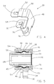
- the terminal cap 20 is illustrated more clearly in Fig. 4. It is a conductive part formed from sheet brass or copper, preferably beryllium copper, and having a flat central portion 48 from which extends two arms 50. Each arm 50 has a rounded deformation 52 midway along and a raised or pressed out finger 54 adjacent the distal end.
- the terminal portion of the terminal cap comprises two terminal legs 56 also extending from the central portion 48.
- the terminal legs 56 form loops in which a lead wire is placed and then the loops are crimped or compressed to grip the wire.
- the lead wire is usually a plastic coated multistrand cable and the insulation is removed from the end and the bared end is placed in one of the loops to make the ,electrical connection while the other loop receives an insulated portion of the lead wire adjacent the bared end to provide stress relief for the electrical connection.
- the bared end of the wire may be soldered to the terminal leg 56.
- a brush 22 is placed in the brush through hole 28 and the spring 24 is then pressed against the outer end of the brush 22.
- the terminal cap 20 is then pressed against the spring 24 and the arms 50 of the terminal cap are inserted into the two passageways 44 of the brush holder and pressed home so that the terminal cap 20 abuts and closes the brush through hole 28.
- the fingers 54 snap out behind the steps 46 in the passageways 44 to prevent the terminal cap 20 from being removed from the brush holder 18, thus capturing the spring 24 and the brush 22 within the brush holder 18.
- the rounded deformations 52 in the arms 50 of the terminal cap act as springs within the passageways 44 removing any looseness in the fitting.
- the terminal cap compresses the spring and is secured to the brush holder by movement in a single direction preventing damage or distortion of the spring caused by lateral movement during assembly.
- Figure 5 is a sectional view of a brush holder assembly according to a second embodiment.
- This embodiment is essentially the same as the first embodiment and corresponding parts are similarly numbered.
- a groove 45 is formed along one side of each of the two passageways 44 and extends through the internal step 46.
- a hole 51 is formed in the terminal cap 20 in alignment with each groove 45. The holes 51 provide access to the grooves 45 for a release pin to resiliently deform or press back the pressed out fingers 54, thereby releasing the fingers 54 from the steps 46 and allowing the cap 20 to be removed. This is desirable in applications where there is access to the brush assemblies so that the brushes can be changed or replaced.
Landscapes
- Engineering & Computer Science (AREA)
- Power Engineering (AREA)
- Motor Or Generator Current Collectors (AREA)
- Motor Or Generator Frames (AREA)
Claims (10)
- Dispositif à porte-balai (12) devant être utilisé dans un moteur universel de faible puissance, comprenant:dans lequel le porte-balai (18) comporte une semelle (30) pour s'appuyer contre une surface extérieure d'un étrier de support (14) et un seul élément de fixation fixant le porte-balai audit étrier,un porte-balai (18) comportant un trou traversant (28) pour recevoir de façon coulissante un balai en carbone (22) et un ressort de balai (24),une borne (56) pour relier le balai (22) à un cordon d'alimentation,un capot (20) pour fermer une extrémité du trou traversant (28), capturant ainsi le ressort de balai (24) à l'intérieur du porte-balai (18) entre le capot (20) et le balai (22),
caractérisé en ce que le porte-balai (18) possède une saillie solidaire (36) sur un côté du porte-balai opposé à l'élément de fixation (42), configurée pour s'appuyer contre une surface intérieure dudit étrier de support (14). - Dispositif à porte-balai selon la revendication 1, dans lequel le seul élément de fixation (42) est un rivet.
- Dispositif à porte-balai selon la revendication 1 ou 2, dans lequel le seul élément de fixation (42) traverse un trou (34) dans le porte-balai (18) qui est aligné avec un trou (40) dans l'étrier de support (14) lorsque la saillie (36) est en appui contre l'étrier (14).
- Dispositif à porte-balai selon l'une quelconque des revendications précédentes,
caractérisé en ce que le porte-balai possède deux passages (44) s'étendant dans la même direction que le trou traversant de balai (28), chacun possédant en son sein un gradin (46), et le capot (20) possède deux bras (50), chacun possédant un doigt surélevé (54), les bras (50) s'étendant le long des passages (44), les doigts surélevés (54) coopérant avec les gradins (46) pour empêcher le retrait des bras (50) des passages (44). - Dispositif à porte-balai selon la revendication 4, dans lequel chacun des deux bras (50) possède une déformation arrondie (52) à un emplacement sur sa longueur, la déformation étant comprimée élastiquement par le passage (44).
- Dispositif à porte-balai selon la revendication 4 ou la revendication 5, dans lequel la borne est solidaire avec le capot (20) et possède une paire de pattes en forme de boucles (56) pour assurer la connexion avec le cordon d'alimentation.
- Dispositif à porte-balai selon l'une quelconque des revendications 4 à 6, dans lequel le capot (20) est formé à partir de cuprobéryllium.
- Dispositif à porte-balai selon l'une quelconque des revendications 4 à 6, dans lequel le capot (20) est en laiton.
- Dispositif à porte-balai selon l'une quelconque des revendications 4 à 8, caractérisé en ce que chaque passage (44) possède une rainure (45) traversant le gradin (46), offrant un accès pour libérer le doigt (54) du gradin (46) pour enlever le capot (20).
- Procédé de montage d'un dispositif à porte-balai selon l'une quelconque des revendications précédentes, dans lequel l'étrier de support (14) possède une ouverture (38) dimensionnée pour recevoir le porte-balai (18), et on monte le porte-balai (18) sur l'étrier (14) en insérant le porte-balai (18) à travers l'ouverture (38) dans l'étrier (14) dans une première direction de sorte que la semelle (30) s'appuie contre la surface extérieure de l'étrier (14) et en déplaçant ensuite le porte-balai dans une deuxième direction perpendiculaire à la première direction de sorte que la saillie (36) s'appuie contre la surface intérieure de l'étrier (14).
Applications Claiming Priority (2)
| Application Number | Priority Date | Filing Date | Title |
|---|---|---|---|
| GBGB0003134.4A GB0003134D0 (en) | 2000-02-12 | 2000-02-12 | Brush holder assembly |
| GB0003134 | 2000-02-12 |
Publications (3)
| Publication Number | Publication Date |
|---|---|
| EP1124306A2 EP1124306A2 (fr) | 2001-08-16 |
| EP1124306A3 EP1124306A3 (fr) | 2003-01-02 |
| EP1124306B1 true EP1124306B1 (fr) | 2004-08-04 |
Family
ID=9885378
Family Applications (1)
| Application Number | Title | Priority Date | Filing Date |
|---|---|---|---|
| EP01301182A Expired - Lifetime EP1124306B1 (fr) | 2000-02-12 | 2001-02-09 | Dispositif porte-balais |
Country Status (7)
| Country | Link |
|---|---|
| US (1) | US6608423B2 (fr) |
| EP (1) | EP1124306B1 (fr) |
| CN (1) | CN1203593C (fr) |
| AT (1) | ATE272910T1 (fr) |
| DE (1) | DE60104575T2 (fr) |
| ES (1) | ES2225421T3 (fr) |
| GB (1) | GB0003134D0 (fr) |
Families Citing this family (12)
| Publication number | Priority date | Publication date | Assignee | Title |
|---|---|---|---|---|
| DE10249157A1 (de) * | 2002-10-22 | 2004-05-06 | Robert Bosch Gmbh | Kontaktelementhalter |
| US6909218B2 (en) * | 2003-02-26 | 2005-06-21 | Black & Decker Inc. | End cap and brush box assembly |
| GB0328386D0 (en) * | 2003-12-06 | 2004-01-14 | Johnson Electric Sa | Brush holder assembly for an electric motor |
| US7049727B2 (en) * | 2004-01-16 | 2006-05-23 | Robert Bosch Gmbh | Integrated brush-holder retention system |
| JP4465284B2 (ja) | 2005-01-31 | 2010-05-19 | 株式会社ミツバ | 小型モータ |
| US7466056B2 (en) | 2006-10-06 | 2008-12-16 | Remi International, Inc | Dynamoelectric machine brush holder assembly and method |
| US7705512B2 (en) | 2006-10-06 | 2010-04-27 | Remy International, Inc. | Dynamoelectric machine conductor |
| US7696666B2 (en) | 2006-10-06 | 2010-04-13 | Remy Technologies, L.L.C. | Dynamoelectric machine grommet |
| ITBO20070575A1 (it) * | 2007-08-07 | 2009-02-08 | Spal Automotive Srl | Macchina elettrica. |
| KR100908373B1 (ko) * | 2007-08-20 | 2009-07-20 | 엘에스산전 주식회사 | 기중차단기의 투입스프링 차징장치에 사용되는 구동모터 |
| CN102842994B (zh) * | 2011-06-21 | 2015-07-22 | 江门马丁电机科技有限公司 | 一种刷握压装装置 |
| CN115441632A (zh) * | 2019-12-24 | 2022-12-06 | 威灵(芜湖)电机制造有限公司 | 电机电刷、电机和洗衣机 |
Family Cites Families (11)
| Publication number | Priority date | Publication date | Assignee | Title |
|---|---|---|---|---|
| DE2635861C2 (de) | 1975-08-13 | 1987-01-08 | S.E.V. Alternateurs, Issy-Les-Moulineaux | Kohlenhalter |
| US4590398A (en) | 1984-01-26 | 1986-05-20 | Kabushiki Kaisha Yaskawa Denki Seisakusho | Brush holder |
| JPH0448134Y2 (fr) * | 1987-05-29 | 1992-11-12 | ||
| GB2219695B (en) * | 1988-06-06 | 1992-07-01 | Johnson Electric Ind Mfg | An electric motor |
| GB2224166A (en) * | 1988-10-13 | 1990-04-25 | Johnson Electric Ind Mfg | Brush supporting gear with switch for an electric motor |
| US4963779A (en) * | 1989-05-15 | 1990-10-16 | Black & Decker, Inc. | Brush holder for an electric motor |
| JPH0649100Y2 (ja) * | 1989-12-04 | 1994-12-12 | 株式会社三ツ葉電機製作所 | 直流機の配線装置 |
| JPH04299043A (ja) * | 1991-03-28 | 1992-10-22 | Tokyo Electric Co Ltd | 整流子電動機のブラシ装置 |
| US5315199A (en) | 1993-04-30 | 1994-05-24 | Ryobi Motor Products Corp. | Bidirectional brush holder assembly |
| DE19712194A1 (de) * | 1997-03-22 | 1998-09-24 | Mannesmann Vdo Ag | Elektromotor |
| GB9814690D0 (en) * | 1998-07-08 | 1998-09-02 | Johnson Electric Sa | Dust guard |
-
2000
- 2000-02-12 GB GBGB0003134.4A patent/GB0003134D0/en not_active Ceased
-
2001
- 2001-02-09 DE DE60104575T patent/DE60104575T2/de not_active Expired - Lifetime
- 2001-02-09 AT AT01301182T patent/ATE272910T1/de not_active IP Right Cessation
- 2001-02-09 EP EP01301182A patent/EP1124306B1/fr not_active Expired - Lifetime
- 2001-02-09 ES ES01301182T patent/ES2225421T3/es not_active Expired - Lifetime
- 2001-02-12 CN CN01116506.5A patent/CN1203593C/zh not_active Expired - Fee Related
- 2001-02-12 US US09/780,344 patent/US6608423B2/en not_active Expired - Lifetime
Also Published As
| Publication number | Publication date |
|---|---|
| EP1124306A3 (fr) | 2003-01-02 |
| DE60104575D1 (de) | 2004-09-09 |
| DE60104575T2 (de) | 2005-08-11 |
| GB0003134D0 (en) | 2000-04-05 |
| US20010013738A1 (en) | 2001-08-16 |
| CN1203593C (zh) | 2005-05-25 |
| CN1310498A (zh) | 2001-08-29 |
| ATE272910T1 (de) | 2004-08-15 |
| US6608423B2 (en) | 2003-08-19 |
| EP1124306A2 (fr) | 2001-08-16 |
| ES2225421T3 (es) | 2005-03-16 |
Similar Documents
| Publication | Publication Date | Title |
|---|---|---|
| JP5528573B2 (ja) | 軸受けシールド | |
| JP4728074B2 (ja) | 電気的な接続端子または接合端子 | |
| US4694214A (en) | Brush holder for dynamoelectric machines | |
| US7038563B2 (en) | Electromagnetic switch for starter | |
| US6608423B2 (en) | Brush holder assembly | |
| EP0638982B1 (fr) | Moteur miniature | |
| JP4986412B2 (ja) | ブラシアセンブリ | |
| JP3051222B2 (ja) | 小型モータ | |
| US20210211022A1 (en) | Stator of an electrical machine, comprising a temperature sensor, and electrical machine comprising such a stator | |
| US5382852A (en) | Miniature motor | |
| EP0645872B1 (fr) | Moteur miniature | |
| US20010013728A1 (en) | Power supply terminal-housing motor | |
| EP1538729B1 (fr) | Porte-balais pour moteur électrique | |
| US20090115266A1 (en) | Power tool with frameless motor and two-piece brush assembly, and method of assembly | |
| US20220384967A1 (en) | Terminal | |
| EP0813757A1 (fr) | Ensemble moteur electrique et contact afferent | |
| JPH06165443A (ja) | 電動機 | |
| US5848918A (en) | Electrical appliance with novel electrical power connector structure | |
| GB2232011A (en) | Terminal adapter in an electric motor | |
| JP2005045872A (ja) | モータにおけるブラシ保持装置 | |
| EP0304528A2 (fr) | Dispositif à balai dans un moteur électrique | |
| JPH07163096A (ja) | ブラシ組立体 | |
| GB2195835A (en) | Anti-chatter brush assembly in an electric motor | |
| JPH083177Y2 (ja) | モータのブラシホルダー構造 | |
| CN120200035A (zh) | 连接器 |
Legal Events
| Date | Code | Title | Description |
|---|---|---|---|
| PUAI | Public reference made under article 153(3) epc to a published international application that has entered the european phase |
Free format text: ORIGINAL CODE: 0009012 |
|
| AK | Designated contracting states |
Kind code of ref document: A2 Designated state(s): AT BE CH CY DE DK ES FI FR GB GR IE IT LI LU MC NL PT SE TR |
|
| AX | Request for extension of the european patent |
Free format text: AL;LT;LV;MK;RO;SI |
|
| PUAL | Search report despatched |
Free format text: ORIGINAL CODE: 0009013 |
|
| AK | Designated contracting states |
Kind code of ref document: A3 Designated state(s): AT BE CH CY DE DK ES FI FR GB GR IE IT LI LU MC NL PT SE TR |
|
| AX | Request for extension of the european patent |
Free format text: AL;LT;LV;MK;RO;SI |
|
| RIC1 | Information provided on ipc code assigned before grant |
Free format text: 7H 02K 5/14 A, 7H 01R 39/38 B |
|
| 17P | Request for examination filed |
Effective date: 20030609 |
|
| 17Q | First examination report despatched |
Effective date: 20030721 |
|
| AKX | Designation fees paid |
Designated state(s): AT BE CH CY DE DK ES FI FR GB GR IE IT LI LU MC NL PT SE TR |
|
| GRAP | Despatch of communication of intention to grant a patent |
Free format text: ORIGINAL CODE: EPIDOSNIGR1 |
|
| GRAP | Despatch of communication of intention to grant a patent |
Free format text: ORIGINAL CODE: EPIDOSNIGR1 |
|
| GRAS | Grant fee paid |
Free format text: ORIGINAL CODE: EPIDOSNIGR3 |
|
| GRAA | (expected) grant |
Free format text: ORIGINAL CODE: 0009210 |
|
| AK | Designated contracting states |
Kind code of ref document: B1 Designated state(s): AT BE CH CY DE DK ES FI FR GB GR IE IT LI LU MC NL PT SE TR |
|
| PG25 | Lapsed in a contracting state [announced via postgrant information from national office to epo] |
Ref country code: AT Free format text: LAPSE BECAUSE OF FAILURE TO SUBMIT A TRANSLATION OF THE DESCRIPTION OR TO PAY THE FEE WITHIN THE PRESCRIBED TIME-LIMIT Effective date: 20040804 Ref country code: TR Free format text: LAPSE BECAUSE OF FAILURE TO SUBMIT A TRANSLATION OF THE DESCRIPTION OR TO PAY THE FEE WITHIN THE PRESCRIBED TIME-LIMIT Effective date: 20040804 Ref country code: CH Free format text: LAPSE BECAUSE OF FAILURE TO SUBMIT A TRANSLATION OF THE DESCRIPTION OR TO PAY THE FEE WITHIN THE PRESCRIBED TIME-LIMIT Effective date: 20040804 Ref country code: BE Free format text: LAPSE BECAUSE OF FAILURE TO SUBMIT A TRANSLATION OF THE DESCRIPTION OR TO PAY THE FEE WITHIN THE PRESCRIBED TIME-LIMIT Effective date: 20040804 Ref country code: LI Free format text: LAPSE BECAUSE OF FAILURE TO SUBMIT A TRANSLATION OF THE DESCRIPTION OR TO PAY THE FEE WITHIN THE PRESCRIBED TIME-LIMIT Effective date: 20040804 Ref country code: NL Free format text: LAPSE BECAUSE OF FAILURE TO SUBMIT A TRANSLATION OF THE DESCRIPTION OR TO PAY THE FEE WITHIN THE PRESCRIBED TIME-LIMIT Effective date: 20040804 Ref country code: FI Free format text: LAPSE BECAUSE OF FAILURE TO SUBMIT A TRANSLATION OF THE DESCRIPTION OR TO PAY THE FEE WITHIN THE PRESCRIBED TIME-LIMIT Effective date: 20040804 |
|
| REG | Reference to a national code |
Ref country code: GB Ref legal event code: FG4D |
|
| REG | Reference to a national code |
Ref country code: CH Ref legal event code: EP |
|
| REG | Reference to a national code |
Ref country code: IE Ref legal event code: FG4D |
|
| REF | Corresponds to: |
Ref document number: 60104575 Country of ref document: DE Date of ref document: 20040909 Kind code of ref document: P |
|
| PG25 | Lapsed in a contracting state [announced via postgrant information from national office to epo] |
Ref country code: SE Free format text: LAPSE BECAUSE OF FAILURE TO SUBMIT A TRANSLATION OF THE DESCRIPTION OR TO PAY THE FEE WITHIN THE PRESCRIBED TIME-LIMIT Effective date: 20041104 Ref country code: GR Free format text: LAPSE BECAUSE OF FAILURE TO SUBMIT A TRANSLATION OF THE DESCRIPTION OR TO PAY THE FEE WITHIN THE PRESCRIBED TIME-LIMIT Effective date: 20041104 Ref country code: DK Free format text: LAPSE BECAUSE OF FAILURE TO SUBMIT A TRANSLATION OF THE DESCRIPTION OR TO PAY THE FEE WITHIN THE PRESCRIBED TIME-LIMIT Effective date: 20041104 |
|
| NLV1 | Nl: lapsed or annulled due to failure to fulfill the requirements of art. 29p and 29m of the patents act | ||
| PG25 | Lapsed in a contracting state [announced via postgrant information from national office to epo] |
Ref country code: IE Free format text: LAPSE BECAUSE OF NON-PAYMENT OF DUE FEES Effective date: 20050209 Ref country code: CY Free format text: LAPSE BECAUSE OF FAILURE TO SUBMIT A TRANSLATION OF THE DESCRIPTION OR TO PAY THE FEE WITHIN THE PRESCRIBED TIME-LIMIT Effective date: 20050209 Ref country code: LU Free format text: LAPSE BECAUSE OF NON-PAYMENT OF DUE FEES Effective date: 20050209 |
|
| REG | Reference to a national code |
Ref country code: CH Ref legal event code: PL |
|
| PG25 | Lapsed in a contracting state [announced via postgrant information from national office to epo] |
Ref country code: MC Free format text: LAPSE BECAUSE OF NON-PAYMENT OF DUE FEES Effective date: 20050228 |
|
| REG | Reference to a national code |
Ref country code: ES Ref legal event code: FG2A Ref document number: 2225421 Country of ref document: ES Kind code of ref document: T3 |
|
| ET | Fr: translation filed | ||
| PLBE | No opposition filed within time limit |
Free format text: ORIGINAL CODE: 0009261 |
|
| STAA | Information on the status of an ep patent application or granted ep patent |
Free format text: STATUS: NO OPPOSITION FILED WITHIN TIME LIMIT |
|
| 26N | No opposition filed |
Effective date: 20050506 |
|
| REG | Reference to a national code |
Ref country code: IE Ref legal event code: MM4A |
|
| PG25 | Lapsed in a contracting state [announced via postgrant information from national office to epo] |
Ref country code: PT Free format text: LAPSE BECAUSE OF NON-PAYMENT OF DUE FEES Effective date: 20050104 |
|
| PGFP | Annual fee paid to national office [announced via postgrant information from national office to epo] |
Ref country code: ES Payment date: 20090317 Year of fee payment: 9 |
|
| PGFP | Annual fee paid to national office [announced via postgrant information from national office to epo] |
Ref country code: GB Payment date: 20090204 Year of fee payment: 9 |
|
| PGFP | Annual fee paid to national office [announced via postgrant information from national office to epo] |
Ref country code: IT Payment date: 20090212 Year of fee payment: 9 |
|
| PGFP | Annual fee paid to national office [announced via postgrant information from national office to epo] |
Ref country code: FR Payment date: 20090213 Year of fee payment: 9 |
|
| GBPC | Gb: european patent ceased through non-payment of renewal fee |
Effective date: 20100209 |
|
| REG | Reference to a national code |
Ref country code: FR Ref legal event code: ST Effective date: 20101029 |
|
| PG25 | Lapsed in a contracting state [announced via postgrant information from national office to epo] |
Ref country code: FR Free format text: LAPSE BECAUSE OF NON-PAYMENT OF DUE FEES Effective date: 20100301 |
|
| REG | Reference to a national code |
Ref country code: ES Ref legal event code: FD2A Effective date: 20110309 |
|
| PG25 | Lapsed in a contracting state [announced via postgrant information from national office to epo] |
Ref country code: GB Free format text: LAPSE BECAUSE OF NON-PAYMENT OF DUE FEES Effective date: 20100209 Ref country code: IT Free format text: LAPSE BECAUSE OF NON-PAYMENT OF DUE FEES Effective date: 20100209 |
|
| PG25 | Lapsed in a contracting state [announced via postgrant information from national office to epo] |
Ref country code: ES Free format text: LAPSE BECAUSE OF NON-PAYMENT OF DUE FEES Effective date: 20110308 |
|
| PG25 | Lapsed in a contracting state [announced via postgrant information from national office to epo] |
Ref country code: ES Free format text: LAPSE BECAUSE OF NON-PAYMENT OF DUE FEES Effective date: 20100210 |
|
| PGFP | Annual fee paid to national office [announced via postgrant information from national office to epo] |
Ref country code: DE Payment date: 20190129 Year of fee payment: 19 |
|
| REG | Reference to a national code |
Ref country code: DE Ref legal event code: R119 Ref document number: 60104575 Country of ref document: DE |
|
| PG25 | Lapsed in a contracting state [announced via postgrant information from national office to epo] |
Ref country code: DE Free format text: LAPSE BECAUSE OF NON-PAYMENT OF DUE FEES Effective date: 20200901 |