EP1124341B1 - Unité de contrôle pour terminal d'un système de communications numérique sans fil et méthode associée - Google Patents
Unité de contrôle pour terminal d'un système de communications numérique sans fil et méthode associée Download PDFInfo
- Publication number
- EP1124341B1 EP1124341B1 EP01200432A EP01200432A EP1124341B1 EP 1124341 B1 EP1124341 B1 EP 1124341B1 EP 01200432 A EP01200432 A EP 01200432A EP 01200432 A EP01200432 A EP 01200432A EP 1124341 B1 EP1124341 B1 EP 1124341B1
- Authority
- EP
- European Patent Office
- Prior art keywords
- control
- control unit
- instant
- timer
- control signals
- Prior art date
- Legal status (The legal status is an assumption and is not a legal conclusion. Google has not performed a legal analysis and makes no representation as to the accuracy of the status listed.)
- Expired - Lifetime
Links
Images


Classifications
-
- H—ELECTRICITY
- H04—ELECTRIC COMMUNICATION TECHNIQUE
- H04W—WIRELESS COMMUNICATION NETWORKS
- H04W88/00—Devices specially adapted for wireless communication networks, e.g. terminals, base stations or access point devices
- H04W88/02—Terminal devices
-
- H—ELECTRICITY
- H04—ELECTRIC COMMUNICATION TECHNIQUE
- H04B—TRANSMISSION
- H04B7/00—Radio transmission systems, i.e. using radiation field
- H04B7/24—Radio transmission systems, i.e. using radiation field for communication between two or more posts
- H04B7/26—Radio transmission systems, i.e. using radiation field for communication between two or more posts at least one of which is mobile
-
- H—ELECTRICITY
- H04—ELECTRIC COMMUNICATION TECHNIQUE
- H04B—TRANSMISSION
- H04B1/00—Details of transmission systems, not covered by a single one of groups H04B3/00 - H04B13/00; Details of transmission systems not characterised by the medium used for transmission
- H04B1/38—Transceivers, i.e. devices in which transmitter and receiver form a structural unit and in which at least one part is used for functions of transmitting and receiving
- H04B1/40—Circuits
- H04B1/401—Circuits for selecting or indicating operating mode
-
- H—ELECTRICITY
- H04—ELECTRIC COMMUNICATION TECHNIQUE
- H04M—TELEPHONIC COMMUNICATION
- H04M1/00—Substation equipment, e.g. for use by subscribers
- H04M1/72—Mobile telephones; Cordless telephones, i.e. devices for establishing wireless links to base stations without route selection
- H04M1/725—Cordless telephones
- H04M1/73—Battery saving arrangements
-
- Y—GENERAL TAGGING OF NEW TECHNOLOGICAL DEVELOPMENTS; GENERAL TAGGING OF CROSS-SECTIONAL TECHNOLOGIES SPANNING OVER SEVERAL SECTIONS OF THE IPC; TECHNICAL SUBJECTS COVERED BY FORMER USPC CROSS-REFERENCE ART COLLECTIONS [XRACs] AND DIGESTS
- Y02—TECHNOLOGIES OR APPLICATIONS FOR MITIGATION OR ADAPTATION AGAINST CLIMATE CHANGE
- Y02D—CLIMATE CHANGE MITIGATION TECHNOLOGIES IN INFORMATION AND COMMUNICATION TECHNOLOGIES [ICT], I.E. INFORMATION AND COMMUNICATION TECHNOLOGIES AIMING AT THE REDUCTION OF THEIR OWN ENERGY USE
- Y02D30/00—Reducing energy consumption in communication networks
- Y02D30/70—Reducing energy consumption in communication networks in wireless communication networks
Definitions
- the invention relates to a control unit for a terminal of a digital, cordless telecommunications system for supplying control signals to other units of the terminal and a method for such a control unit.
- the typical structure of a terminal is in FIG. 1 shown.
- the radio control unit 2 is controlled by a control device 1 (BMC: Burst Mode Controller).
- the control device 1 is responsible for the time-critical processing of the data to be transmitted and received. In addition, it outputs control signals to the control lines of the radio control unit 2.
- the control device 1 is in turn controlled by a microcontroller 3, which performs protocol functions and other less time-critical functions.
- a further unit 4 may be provided which performs digital signal processing of the data to be transmitted or received.
- the microcontroller 3 and the digital signal processing unit 4 finally have access to the applications 5 of the terminal.
- FIG. 2 A more detailed structure of the control device 1 is shown in FIG. 2 shown.
- the main components of the control device 1 are a control unit 10 and a data processing unit 11.
- the control unit 10 receives commands 20 from the microcontroller 3, according to which it controls the output of control signals 22 on control lines to the radio control unit 2 and generates and outputs control signals 23 for the data processing unit 11. From the data processing unit 11, the control unit 10 also receives feedback information 24, which can likewise influence the control behavior of the control unit 10.
- the data processing unit 11 is in turn used to apply certain functions to the received 27,29 and the 26,28 data bits to be sent, such as encryption, scrambling 12,14 or generating a cyclic redundancy codes (CRC) 13.
- CRC cyclic redundancy codes
- Both the control unit 10 and the data processing unit 11 can provide status information 21, 25 to the microcontroller 3.
- the control unit of a control device is typically implemented as a hardware automatism. This causes problems as soon as a change in the output of the control signals is required. Thus, any change in the format of the data packets requires a redesign of the controller even if the same data processing functions are to be used and only a different bit timing is provided. Likewise, adding or removing data processing functions as well as a change in the specification of the radio interface or timing for the radio control signals requires a redesign of the control unit. Thus, the hardware of a control unit for a particular telecommunications standard, such as DECT, only with considerable adaptation effort for other telecommunications systems, such as the US ISM band system, usable.
- a baseband control unit is known from GSM, which dispenses with the automation implemented in the hardware for the output of control signals.
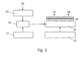
- the unit used instead will be in FIG. 3
- a microcontroller writes values for an event containing a control signal into a control signal register 30 and the values for a time at which the control signals of the event are to be output to the control lines 36 connected to the control signal register 30 are stored in a time register 31.
- a comparator 32 the time from the timing register 31 is constantly compared with the time given by a timer 32.
- the timer 32 is controlled by a local clock generator 35. If coincident, the event is output from the control signal register 30 via an output register 34 to the control lines 36.
- the control lines may, for example, a radio control unit provide control signals 38 and also supply control signals 37 to a data processing unit.
- a corresponding proposal for a GSM mobile device is for example in the document DE 197 47 275 A1 to find.
- control units known from the GSM application can not be easily transferred to applications in the digital, cordless area.
- Applications such as DECT with 1152 kbit / s have a much higher bit rate than GSM with 270 kbit / s.
- DECT requires the support of multiple connections simultaneously. This leads to a considerable amount of software processing and to real-time requirements that are currently practically unattainable. So is in worst case, a response time within the time of a bit, ie within 0.87 ⁇ s required.
- PSTN public switched telephone networks
- off-line processing of the received data that is, non-real-time processing, is not possible.
- processing steps such as decrypting and checking a checksum, etc., must be applied to the received data immediately and with the timing of the received signal data. For this reason, it is also not possible to use GSM for a reference time dependent on the local system time.
- the invention has for its object to provide an improved, flexible and energy-saving control unit for a terminal of a digital wireless telecommunication system for supplying control signals to other units of the terminal.
- the invention is also based on the object to provide a method that allows the use of an improved, flexible and energy-saving control unit for a terminal of a cordless telecommunications system.
- control unit having the features of claim 1.
- control unit according to the invention and the inventive method are based on a software control with sufficient hardware support, whereby a great flexibility is achieved, but at the same time excessive demands on the microcontroller performance are avoided.
- the invention allows adaptations to changing conditions without requiring a redesign of the hardware.
- it is easily possible to adapt to applications of different systems by adjusting the events and times supplied by the microcontroller to the register arrays become.
- it is possible to respond to changes in units connected to the control lines, such as in a radio interface or a data processing unit, for example when control lines are to be occupied differently or the timing and the signal level at the radio interface are to be changed.
- the invention can also be used in systems with high data rates such as DECT without significant software load by the use of the register arrays, since the microcontroller can load several commands simultaneously and thus does not have to respond in the time period of a single bit, so that the real time requirements can be more easily realized.
- FIGS. 1 to 3 have already been described in the prior art.
- FIG. 4 is the structure of a according to FIG. 2 in a control device 1 integrated control unit 10 is shown schematically, wherein the control device 1 in turn accordingly FIG. 1 forms a part of a terminal.
- the control unit is divided into three sub-areas, a main control area, a reception control area and a transmission control area, all of which have a similar arrangement.
- Each of the three subareas has a comparator 42, 52, 62 with controlling access to an output register 44, 54, 64.
- the inputs of the comparators 42, 52, 62 are in each case connected to a timer 43, 53, 63 and a timing register array 41, 51, 61.
- the inputs of the output registers 44,54,64 are each connected to a control signal register array 40,50,60 and the outputs 46,56,66 each with control lines.
- An in FIG. 4 Unillustrated microcontroller has access to both the timing 41,51,61 and the control signal register array 40,50,60.
- the timer 63 of the main control area is controlled by a local clock 65.
- the outputs 66,66a, 66b of the output register 64 are connected via control lines on the one hand to a radio control unit and to elements of a data processing unit, on the other hand respectively to an input 48a or 58a of the timer 43 of the receive control section and the timer 53 of the transmission control section.
- the timer 43 of the receive control section has, in addition to the input 48a connected to the output register 64 of the main control section, three further inputs 45, 48b, 48c. Via an input 45, it receives a timing obtained from the received data. Another input 48c is connected to a packet detection unit (not shown). Finally, an input 48b of the timer 43 is connected to one of the outputs 46a of the output register 44 of the receive control section. The remaining outputs 46 of the output register 44 are connected to the elements of the data processing unit which process the received data packets in real time.
- the timing generator 53 of the transmission control area is controlled by the local timing 55, as is the timing 63 of the main control area.
- Another input 58b of the timer 53 of the transmission control area is connected to one of the outputs 56a of the output register 54 of the transmission control area.
- the remaining outputs 56 of the output register 54 are connected to the elements of the data processing unit, which process the data packets to be sent.
- the timers 43, 53, 63 of the three subregions each consist of a bit counter whose length is for example 11520. Also possible is a combination of a bit counter with a length of 480 and a time slot counter with a length of 24 for a timer in which the bit counter counts the bits within a time slot and increments each time the last bit of a time slot of a frame of the time slot counter becomes.
- a pure bit counter results in greater flexibility in processing variable time slot structures that may occur in some systems, such as when the different time slots within a frame have different lengths.
- the use of a bit counter facilitates the simultaneous consideration of multiple clock presets, since a second clock preset can simply be treated as a clock offset in the bit counter. If a time slot counter is used, two counters are required for the offset calculations in this case, and the resulting overflow monitoring etc. increase the software effort.
- the three sub-areas off FIG. 4 work each similar to the control unit FIG. 3
- a comparator compares a given system time with a time from one register and, depending thereon, causes the output of control signals from events stored in another register.
- the microcontroller can load a number of instructions consisting of an event and the time assigned thereto at once.
- the hardware cyclically accesses the registers of the arrays 41, 51, 61 and 40, 50, 60.
- a pointer 47,57,67 indicates, which are currently the current time and the current control signal.
- the pointer 47,57,67 is preferably also by the microcontroller controlled.
- the control signals contained in the current event are transferred to the control lines via the output register 44, 54, 64 the pointer 47, 57, 67 is continued, and the next time and event are ready.
- the microcontroller no longer needs to respond to new data within the time of a single bit, allowing real-time processing even at high data rates.
- control signals related to the radio control usually do not occur during a time slot, that is, while processing of a data packet is in progress.
- the events can also be divided so that only one event with a smaller number of control signals has to be output per time. The width of the events, and thus the amount of data that must be programmed by the microcontroller for each time, is thus significantly reduced, which the load of the microcontroller benefits.
- the main control area is responsible for the output of control signals to the control lines to the radio control unit.
- the main control area can be used to provide control data for data processing that is not directly related to bits within a data packet, that is, synchronization with incoming data is not required. For example, these can be control signals for switching synchronization windows on and off, which can be carried out before the first bit of a data packet has been received.
- the timer 63 of the main control area is constantly running. Otherwise, the main control panel can be turned off in times of no activity to save energy.
- the send control section controls all data processing functions that depend on the bit position within a data packet to be sent. It is active only during the transmission of data packets and is activated by the main control section via the control line which connects the output control register 64 of the main control section to the timer 53 of the transmission control section. By the start signal, the timer 53 starts to run according to the clock of the data packets to be transmitted. At each restart, the transmit control section will start reading again at the first stored time and event, not at the last pointer position before turning off.
- the events of the transmit control area have a control signal which is transmitted via the control line from the output register 54 to the timer 53 of the transmit control area and which is suitable for stopping execution of further commands until reactivation by the main control area he follows.
- the receive control section controls all data processing functions that depend on the bit position within a received data packet. It is only active when receiving data packets.
- the reception control area is activated either like the transmission control area by a control signal of the main control area or by a start signal of the data processing units which are responsible for packets to be received if they detect the start of a packet, for example by the detection of a synchronization field (synchronization field detection).
- the timer 43 of the receive control area also begins to run with the start signal.
- the timer 43 is given a clock that does not come from a local clock generator but is obtained from the received data. As a result, the processing of the received data can take place independently of the system clocking.
- the receive control section also starts reading again at each restart with the first stored time and the first event. Again, one of the Control signals of their own events disable the receive control area via the control line from the output register 44 to the timer 43.
- Control lines can also be used in all three subregions to output interrupts to the microcontroller so that the microcontroller can synchronously control the various subregions.
- the receive control area and the send control area require only one timer 43, 53, which only comprises the length of a single packet. These timers 43, 53 may thus be shorter than the system timer 63 used by the main control area, thus requiring less memory and less processing power for calculating and writing.
- the times specified in the receive control area and transmit control area each have a certain offset from a fixed position within a data packet, so that they remain unaffected by changes in the system timing. These times and the associated control signals can thus be stored as static data and do not need to be recalculated each time by the microcontroller, which further reduces the processing load.
Landscapes
- Engineering & Computer Science (AREA)
- Computer Networks & Wireless Communication (AREA)
- Signal Processing (AREA)
- Mobile Radio Communication Systems (AREA)
- Telephone Function (AREA)
Claims (8)
- Unité de commande (10) pour un appareil terminal d'un système de télécommunications numérique sans fil pour la délivrance de signaux de commande à d'autres unités de l'appareil terminal avec :- un registre de signaux de commande (40, 54, 60) chargeable par un microcontrôleur (3) avec différents événements réunis à partir de signaux de commande, dans lequel, parmi les événements, respectivement un événement est choisi comme événement actuel,- un registre de points temporels pouvant être chargé par le microcontrôleur (3) en points temporels différents, registre de points temporels (41, 51, 61) qui est apte, respectivement, à mettre à disposition un point temporel affecté à l'événement actuel en tant que point temporel actuel,- une horloge (43, 53, 63) pour l'indication d'un temps correspondant à une synchronisation locale ou à partir d'une synchronisation à partir de données reçues,- un comparateur (42, 52, 62) pour la comparaison du temps mis à disposition par l'horloge (43, 53, 63) avec le point temporel actuel mis à disposition par le registre de points temporels (41, 51, 61), et- un registre d'émission (44, 54, 64) piloté par le comparateur (42, 52, 62) et relié aux conduites de commande, dans lequel, en cas de coïncidence constatée par le comparateur (42, 52, 62) du temps fourni par l'horloge (43, 53, 63) avec le point temporel actuel, s'inscrit l'événement actuel et qui est apte à émettre les signaux de commande reçus par l'intermédiaire des conduites de commande en tant que signaux de commande pour les autres unités, caractérisé en ce que l'unité de commande comprend au moins deux zones secondaires qui, respectivement, présentent un registre de signaux de commande (40, 50, 60), une horloge (43, 53, 63), un registre de points temporels (41, 51, 61), un comparateur (42, 52, 62) et un registre d'émission (44, 54, 64), de sorte que les signaux de commande émis peuvent être répartis en au moins deux événements dont respectivement un événement peut être traité par l'une des zones secondaires.
- Unité de commande (10) selon la revendication 1, caractérisée en ce qu'en tant que zone secondaire, on dispose d'au moins une zone de commande principale pour l'émission de signaux de commande qui ne se rapportent pas directement aux bits à l'intérieur d'un paquet de données, en particulier de signaux de commande pour une unité de commande radio (2) commandant une interface radio et/ou pour une unité de traitement de données (11), une zone de commande de réception pour l'émission de signaux de commande nécessaires pour le traitement des données reçues en temps réel et une zone de commande d'émission pour émettre les signaux de commande nécessaires pour le traitement des données à envoyer en temps réel.
- Unité de commande (10) selon la revendication 1 ou 2, caractérisée en ce que chacune des zones secondaires présente une horloge propre (43, 53, 63) qui est commandée soit en fonction d'une temporisation locale (55, 65), soit en fonction de la temporisation de paquets de données arrivants (45).
- Unité de commande (10) selon l'une des revendications 1 à 3, caractérisée en ce qu'une première des zones secondaires est apte à activer au moins une autre des zones secondaires par l'intermédiaire d'un signal de commande prévu dans l'événement actuel de la première zone secondaire, et en ce qu'au moins une autre zone secondaire se désactive par l'intermédiaire d'un signal de commande prévu dans l'événement actuel de l'autre zone secondaire.
- Unité de commande (10) selon l'une des revendications précédentes, caractérisée en ce qu'au moins l'une des horloges concernées (43, 53, 63) est conçue en tant que simple compteur de bits.
- Unité de commande (10) selon l'une des revendications précédentes, caractérisée en ce qu'elle est intégrée avec une unité de traitement de données (11) pour le traitement de données reçues et de données à envoyer dans un dispositif de commande (1) conçu sous forme de puce.
- Appareil terminal d'un système de télécommunications sans fil qui présente une unité de commande (10) selon l'une des revendications précédentes.
- Procédé pour une unité de commande (10) d'un appareil terminal d'un système de télécommunications sans fil pour la fourniture de signaux de commande à d'autres unités de l'appareil terminal, dans lequel l'unité de commande (10) présente un registre de signaux de commande (40, 50, 60) raccordé à un registre d'émission (44, 54, 64), ainsi qu'un comparateur raccordé à une horloge (43, 53, 63) et un registre de points temporels (41, 51, 61) avec l'accès de commande au registre d'émission (44, 54, 64) qui présente les étapes suivantes :a) écriture de différents événements contenant des signaux de commande dans le registre de signaux de commande (40, 50, 60) par un microcontrôleur (3),b) écriture de respectivement des points temporels affectés à un événement dans le registre de points temporels par le microcontrôleur (3),c) détermination de l'événement actuel et du point temporel actuel affecté à l'événement actuel,d) fourniture du point temporel actuel au comparateur (42, 52, 62),e) vérification constante dans le comparateur (42, 52, 62) si le point temporel actuel coïncide à une valeur temps fournie continuellement au comparateur (42, 52, 62) de l'horloge (43, 53, 63), etf) en cas de coïncidence, chargement de l'événement actuel dans le registre d'émission (44, 54, 64) et émission du signal de commande reçu en provenance du registre d'émission (44, 54, 64) sur les lignes de commande raccordées, caractérisé en ce que l'unité de commande comprend au moins deux zones secondaires qui, respectivement, présentent un registre de signaux de commande (40, 50, 60), une horloge (43, 53, 63), un registre de points temporels (41, 51, 61), un comparateur (42, 52, 62) et un registre d'émission (44, 54, 64), tandis que les signaux de commande à émettre peuvent être répartis sur au moins deux événements, dont respectivement un événement peut être traité par l'une des zones secondaires.
Applications Claiming Priority (2)
| Application Number | Priority Date | Filing Date | Title |
|---|---|---|---|
| DE10005911A DE10005911A1 (de) | 2000-02-10 | 2000-02-10 | Steuereinheit für ein Endgerät eines digitalen schnurlosen Telekommunikationssystems sowie Verfahren für eine solche Steuereinheit |
| DE10005911 | 2000-02-10 |
Publications (3)
| Publication Number | Publication Date |
|---|---|
| EP1124341A2 EP1124341A2 (fr) | 2001-08-16 |
| EP1124341A3 EP1124341A3 (fr) | 2004-10-06 |
| EP1124341B1 true EP1124341B1 (fr) | 2008-04-30 |
Family
ID=7630460
Family Applications (1)
| Application Number | Title | Priority Date | Filing Date |
|---|---|---|---|
| EP01200432A Expired - Lifetime EP1124341B1 (fr) | 2000-02-10 | 2001-02-06 | Unité de contrôle pour terminal d'un système de communications numérique sans fil et méthode associée |
Country Status (6)
| Country | Link |
|---|---|
| US (1) | US6763239B2 (fr) |
| EP (1) | EP1124341B1 (fr) |
| JP (1) | JP4612205B2 (fr) |
| KR (1) | KR100756091B1 (fr) |
| CN (1) | CN1246980C (fr) |
| DE (2) | DE10005911A1 (fr) |
Families Citing this family (6)
| Publication number | Priority date | Publication date | Assignee | Title |
|---|---|---|---|---|
| US7181190B2 (en) * | 2004-04-30 | 2007-02-20 | Microsoft Corporation | Method for maintaining wireless network response time while saving wireless adapter power |
| EP1927949A1 (fr) * | 2006-12-01 | 2008-06-04 | Thomson Licensing | Réseau d'éléments de traitement avec registres locaux |
| DE102009029663A1 (de) * | 2009-09-22 | 2011-03-24 | Robert Bosch Gmbh | Verfahren zur Kommunikation zwischen einem Mikrokontroller und einem Endstufenbaustein sowie Endstufenbaustein |
| CN102740489B (zh) * | 2011-04-15 | 2015-09-16 | 中兴通讯股份有限公司 | 一种实现无绳电话通话的方法和装置 |
| CN118276040B (zh) * | 2022-12-30 | 2026-01-02 | 深圳市速腾聚创科技有限公司 | 雷达主控芯片和激光雷达设备 |
| CN119473801B (zh) * | 2025-01-09 | 2025-07-11 | 牛芯半导体(深圳)有限公司 | 基于axi协议的总线超时监测方法、装置及系统 |
Family Cites Families (13)
| Publication number | Priority date | Publication date | Assignee | Title |
|---|---|---|---|---|
| US5185880A (en) * | 1989-06-05 | 1993-02-09 | Matsushita Electric Industrial Co., Ltd. | Stored instructions executing type timing signal generating system |
| US4941155A (en) * | 1989-11-16 | 1990-07-10 | Bell Communications Research, Inc. | Method and circuitry for symbol timing and frequency offset estimation in time division multiple access radio systems |
| DE4107729A1 (de) * | 1991-03-11 | 1992-09-17 | Philips Patentverwaltung | Anordnung zur erzeugung von digitalsignalen |
| TW327488U (en) * | 1991-05-29 | 1998-02-21 | Video Tech Eng | Digital cordless telephone apparatus |
| JP3343807B2 (ja) * | 1995-11-14 | 2002-11-11 | 松下電器産業株式会社 | タイミング信号発生装置 |
| US5978688A (en) * | 1995-12-29 | 1999-11-02 | Advanced Micro Devices, Inc. | Apparatus and method for protocol interface |
| JP3907704B2 (ja) * | 1996-10-24 | 2007-04-18 | コーニンクレッカ フィリップス エレクトロニクス エヌ ヴィ | ディジタルワイヤレス通信システム及びワイヤレス無線局 |
| JPH10304040A (ja) | 1997-04-25 | 1998-11-13 | Sony Corp | 電話機に対する情報データの記憶方法 |
| JP2901574B2 (ja) | 1997-06-05 | 1999-06-07 | 日本電気アイシーマイコンシステム株式会社 | クロック入力回路 |
| DE19747275A1 (de) * | 1997-10-25 | 1999-04-29 | Philips Patentverwaltung | Mobilfunkgerät mit einem Steuersignalgenerator |
| JP3497470B2 (ja) * | 1998-05-11 | 2004-02-16 | インフィネオン テクノロジース アクチエンゲゼルシャフト | タイミング装置とタイミング方法 |
| KR20000013139A (ko) * | 1998-08-05 | 2000-03-06 | 최문현 | 이동통신 단말기 및 이동통신 단말기용 데이터 저장장치 |
| KR100594687B1 (ko) * | 1998-12-24 | 2006-10-04 | 엘지전자 주식회사 | 휴대용단말기에서 대량의 데이타 저장 방법 |
-
2000
- 2000-02-10 DE DE10005911A patent/DE10005911A1/de not_active Withdrawn
-
2001
- 2001-02-06 DE DE50113903T patent/DE50113903D1/de not_active Expired - Lifetime
- 2001-02-06 EP EP01200432A patent/EP1124341B1/fr not_active Expired - Lifetime
- 2001-02-06 CN CNB011116439A patent/CN1246980C/zh not_active Expired - Fee Related
- 2001-02-07 US US09/778,867 patent/US6763239B2/en not_active Expired - Fee Related
- 2001-02-08 JP JP2001032110A patent/JP4612205B2/ja not_active Expired - Fee Related
- 2001-02-08 KR KR1020010006100A patent/KR100756091B1/ko not_active Expired - Fee Related
Also Published As
| Publication number | Publication date |
|---|---|
| JP2001268164A (ja) | 2001-09-28 |
| DE10005911A1 (de) | 2001-08-16 |
| CN1308424A (zh) | 2001-08-15 |
| CN1246980C (zh) | 2006-03-22 |
| US20010024958A1 (en) | 2001-09-27 |
| KR20010082068A (ko) | 2001-08-29 |
| US6763239B2 (en) | 2004-07-13 |
| DE50113903D1 (de) | 2008-06-12 |
| JP4612205B2 (ja) | 2011-01-12 |
| KR100756091B1 (ko) | 2007-09-05 |
| EP1124341A3 (fr) | 2004-10-06 |
| EP1124341A2 (fr) | 2001-08-16 |
Similar Documents
| Publication | Publication Date | Title |
|---|---|---|
| DE3787410T2 (de) | Veränderbare Steuerungs- und Datenübertragungsgeschwindigkeiten in hocheffizienten Multiplexern. | |
| DE3115455C2 (fr) | ||
| DE3812611C2 (de) | Basisstation für ein drahtloses digitales Telefonsystem | |
| DE69433858T2 (de) | Methode und Vorrichtung zum Austausch unterschiedlicher Arten von Daten während verschiedener Zeitintervallen | |
| DE60111153T2 (de) | Funkkommunikationssystem mit Zeitüberschreitungssteuerung und flexible Intervalleinstellung | |
| DE2848255C2 (fr) | ||
| WO2009109590A1 (fr) | Système de communication comprenant un bus can et un procédé permettant de faire fonctionner un tel système de communication | |
| EP3198967B1 (fr) | Station de radiocommunication de base et système avec ladite station de radiocommunication de base | |
| EP0021290B1 (fr) | Procédé et circuit de synchronisation pour la transmission de signaux d'information numériques | |
| DE102019204115A1 (de) | Teilnehmerstation für ein serielles Bussystem und Verfahren zur Kommunikation in einem seriellen Bussystem | |
| DE69631612T2 (de) | Elektronische Geräte und deren Betriebsartsteuerung | |
| EP1509005B1 (fr) | Méthode et appareil pour la transmission de données par diffusion dans un réseau bus | |
| EP1989598B1 (fr) | Procede, reseau de communication et unite de commande permettant une transmission cyclique de donnees | |
| EP1124341B1 (fr) | Unité de contrôle pour terminal d'un système de communications numérique sans fil et méthode associée | |
| EP0530749B1 (fr) | Méthode et dispositif pour la synchronisation d'un générateur d'horloge d'un système de commutation de communication | |
| EP1428340B1 (fr) | Procede et dispositif pour produire des interruptions de programme au niveau d'utilisateurs d'un systeme de bus, et systeme de bus correspondant | |
| EP1763768A2 (fr) | Procédé et dispositif pour commander un système de bus et système de bus correspondant | |
| EP1357707B1 (fr) | Méthode pour transférer des messages via un système de bus | |
| DE2217178B2 (de) | Schaltungsanordnung zur Interpolation der Ausgangscodes von PCM-Übertragungssystemen | |
| DE60104465T2 (de) | Verfahren und Vorrichtung zur Verteilung eines Synchronisationssignales in einem Nachrichtenübertragungsnetzwerk | |
| EP1078458B1 (fr) | Dispositif et procede de synchronisation | |
| EP2345209B1 (fr) | Procédé et dispositif de transmission de données via les noeuds d'un réseau | |
| EP1820111B1 (fr) | Ensemble bloc de communication muni d'un module interface et module interface | |
| EP1095338A2 (fr) | Module can | |
| DE102006060081B3 (de) | Kommunikationsvorrichtung zur Kommunikation nach einer Master-Slave-Kommunikationsvorschrift |
Legal Events
| Date | Code | Title | Description |
|---|---|---|---|
| PUAI | Public reference made under article 153(3) epc to a published international application that has entered the european phase |
Free format text: ORIGINAL CODE: 0009012 |
|
| AK | Designated contracting states |
Kind code of ref document: A2 Designated state(s): AT BE CH CY DE DK ES FI FR GB GR IE IT LI LU MC NL PT SE TR |
|
| AX | Request for extension of the european patent |
Free format text: AL;LT;LV;MK;RO;SI |
|
| RAP1 | Party data changed (applicant data changed or rights of an application transferred) |
Owner name: PHILIPS CORPORATE INTELLECTUAL PROPERTY GMBH Owner name: KONINKLIJKE PHILIPS ELECTRONICS N.V. |
|
| RAP1 | Party data changed (applicant data changed or rights of an application transferred) |
Owner name: KONINKLIJKE PHILIPS ELECTRONICS N.V. Owner name: PHILIPS INTELLECTUAL PROPERTY & STANDARDS GMBH |
|
| PUAL | Search report despatched |
Free format text: ORIGINAL CODE: 0009013 |
|
| AK | Designated contracting states |
Kind code of ref document: A3 Designated state(s): AT BE CH CY DE DK ES FI FR GB GR IE IT LI LU MC NL PT SE TR |
|
| AX | Request for extension of the european patent |
Extension state: AL LT LV MK RO SI |
|
| RIC1 | Information provided on ipc code assigned before grant |
Ipc: 7H 04B 7/26 A Ipc: 7H 04J 3/06 B |
|
| 17P | Request for examination filed |
Effective date: 20050406 |
|
| AKX | Designation fees paid |
Designated state(s): DE FR GB |
|
| 17Q | First examination report despatched |
Effective date: 20060728 |
|
| RAP1 | Party data changed (applicant data changed or rights of an application transferred) |
Owner name: PHILIPS INTELLECTUAL PROPERTY & STANDARDS GMBH Owner name: NXP B.V. |
|
| GRAP | Despatch of communication of intention to grant a patent |
Free format text: ORIGINAL CODE: EPIDOSNIGR1 |
|
| GRAS | Grant fee paid |
Free format text: ORIGINAL CODE: EPIDOSNIGR3 |
|
| GRAA | (expected) grant |
Free format text: ORIGINAL CODE: 0009210 |
|
| AK | Designated contracting states |
Kind code of ref document: B1 Designated state(s): DE FR GB |
|
| RAP1 | Party data changed (applicant data changed or rights of an application transferred) |
Owner name: DSP GROUP SWITZERLAND AG Owner name: PHILIPS INTELLECTUAL PROPERTY & STANDARDS GMBH |
|
| REG | Reference to a national code |
Ref country code: GB Ref legal event code: FG4D Free format text: NOT ENGLISH |
|
| REF | Corresponds to: |
Ref document number: 50113903 Country of ref document: DE Date of ref document: 20080612 Kind code of ref document: P |
|
| RAP2 | Party data changed (patent owner data changed or rights of a patent transferred) |
Owner name: DSP GROUP SWITZERLAND AG |
|
| RAP2 | Party data changed (patent owner data changed or rights of a patent transferred) |
Owner name: DSP GROUP SWITZERLAND AG |
|
| ET | Fr: translation filed | ||
| PLBE | No opposition filed within time limit |
Free format text: ORIGINAL CODE: 0009261 |
|
| STAA | Information on the status of an ep patent application or granted ep patent |
Free format text: STATUS: NO OPPOSITION FILED WITHIN TIME LIMIT |
|
| 26N | No opposition filed |
Effective date: 20090202 |
|
| PGFP | Annual fee paid to national office [announced via postgrant information from national office to epo] |
Ref country code: DE Payment date: 20140219 Year of fee payment: 14 |
|
| PGFP | Annual fee paid to national office [announced via postgrant information from national office to epo] |
Ref country code: FR Payment date: 20140219 Year of fee payment: 14 |
|
| PGFP | Annual fee paid to national office [announced via postgrant information from national office to epo] |
Ref country code: GB Payment date: 20140218 Year of fee payment: 14 |
|
| REG | Reference to a national code |
Ref country code: DE Ref legal event code: R119 Ref document number: 50113903 Country of ref document: DE |
|
| GBPC | Gb: european patent ceased through non-payment of renewal fee |
Effective date: 20150206 |
|
| REG | Reference to a national code |
Ref country code: FR Ref legal event code: ST Effective date: 20151030 |
|
| PG25 | Lapsed in a contracting state [announced via postgrant information from national office to epo] |
Ref country code: GB Free format text: LAPSE BECAUSE OF NON-PAYMENT OF DUE FEES Effective date: 20150206 Ref country code: DE Free format text: LAPSE BECAUSE OF NON-PAYMENT OF DUE FEES Effective date: 20150901 |
|
| PG25 | Lapsed in a contracting state [announced via postgrant information from national office to epo] |
Ref country code: FR Free format text: LAPSE BECAUSE OF NON-PAYMENT OF DUE FEES Effective date: 20150302 |