EP1124354A2 - Multiplex-Kommunikationsverfahren, Vorrichtung und System - Google Patents
Multiplex-Kommunikationsverfahren, Vorrichtung und System Download PDFInfo
- Publication number
- EP1124354A2 EP1124354A2 EP00115303A EP00115303A EP1124354A2 EP 1124354 A2 EP1124354 A2 EP 1124354A2 EP 00115303 A EP00115303 A EP 00115303A EP 00115303 A EP00115303 A EP 00115303A EP 1124354 A2 EP1124354 A2 EP 1124354A2
- Authority
- EP
- European Patent Office
- Prior art keywords
- data
- node
- nodes
- transmission
- token
- Prior art date
- Legal status (The legal status is an assumption and is not a legal conclusion. Google has not performed a legal analysis and makes no representation as to the accuracy of the status listed.)
- Withdrawn
Links
- 238000004891 communication Methods 0.000 title claims abstract description 149
- 238000000034 method Methods 0.000 title claims abstract description 105
- 230000005540 biological transmission Effects 0.000 claims abstract description 126
- 238000003860 storage Methods 0.000 claims abstract description 61
- 230000000875 corresponding effect Effects 0.000 description 16
- 230000006870 function Effects 0.000 description 10
- 230000001276 controlling effect Effects 0.000 description 8
- 238000010586 diagram Methods 0.000 description 8
- 238000012546 transfer Methods 0.000 description 7
- 238000012545 processing Methods 0.000 description 4
- 230000001360 synchronised effect Effects 0.000 description 4
- 230000001174 ascending effect Effects 0.000 description 2
- 230000002596 correlated effect Effects 0.000 description 2
- 238000013500 data storage Methods 0.000 description 2
- 230000007423 decrease Effects 0.000 description 2
- 238000012986 modification Methods 0.000 description 2
- 230000004048 modification Effects 0.000 description 2
- 239000013256 coordination polymer Substances 0.000 description 1
- 238000013524 data verification Methods 0.000 description 1
- 230000003111 delayed effect Effects 0.000 description 1
- 230000000694 effects Effects 0.000 description 1
- 238000004519 manufacturing process Methods 0.000 description 1
- 238000004904 shortening Methods 0.000 description 1
- 238000012795 verification Methods 0.000 description 1
Images


Classifications
-
- H—ELECTRICITY
- H04—ELECTRIC COMMUNICATION TECHNIQUE
- H04L—TRANSMISSION OF DIGITAL INFORMATION, e.g. TELEGRAPHIC COMMUNICATION
- H04L12/00—Data switching networks
- H04L12/28—Data switching networks characterised by path configuration, e.g. LAN [Local Area Networks] or WAN [Wide Area Networks]
- H04L12/40—Bus networks
- H04L12/407—Bus networks with decentralised control
- H04L12/417—Bus networks with decentralised control with deterministic access, e.g. token passing
-
- H—ELECTRICITY
- H04—ELECTRIC COMMUNICATION TECHNIQUE
- H04L—TRANSMISSION OF DIGITAL INFORMATION, e.g. TELEGRAPHIC COMMUNICATION
- H04L49/00—Packet switching elements
- H04L49/90—Buffering arrangements
-
- H—ELECTRICITY
- H04—ELECTRIC COMMUNICATION TECHNIQUE
- H04L—TRANSMISSION OF DIGITAL INFORMATION, e.g. TELEGRAPHIC COMMUNICATION
- H04L1/00—Arrangements for detecting or preventing errors in the information received
- H04L1/12—Arrangements for detecting or preventing errors in the information received by using return channel
- H04L1/16—Arrangements for detecting or preventing errors in the information received by using return channel in which the return channel carries supervisory signals, e.g. repetition request signals
Definitions
- the present invention relates to a multiplex communication method, a multiplex communication device and a multiplex communication system for implementing multiplex communication by means of token passing.
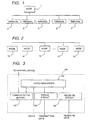
- FIG. 1 shows the structure of a remote I/O communication system.
- a plurality of terminals 2 are connected with a host unit 1 by LAN and each terminal 2 exchanges information by accessing to a host unit 1.
- the terminals 2 can make communication from each other only through the host unit 1 in this communication method.
- an arbitrator within the host unit 1 arbitrates the accesses. Normally, a priority is given to each terminal 2 and the arbitrator permits the access of the terminal 2 in accordance to the priority.
- FIG. 2 shows the structure of a communication system using the token passing communication method.
- a plurality of nodes 10 is connected in LAN and data called as token representing a right of transmission circulates on the LAN. Only node obtaining the token obtains the data transmission right. The node which has finished transmission releases the token and sends it to the next node.
- the communication is controlled so that the plurality of nodes does not transmit data simultaneously by causing the nodes to transmit data one after another by circulating the token.
- Another object of the invention is to improve the token passing communication method and to provide a multiplex communication method which provides new functions.
- a token is circulated among a plurality of nodes, a node receiving the token has a data transmission right, and the node obtaining the data transmission right transmits data by specifying another specific node as a transmission destination and wherein each of the plurality of nodes has a storage unit having a plurality of storage areas for each storing the data transmitted from the other plurality of nodes, wherein the node specified as the transmission destination and each of the nodes not specified as the transmission destination comprises steps of receiving the data transmitted from the node obtaining the data transmission right; and of storing the received data in the storage area corresponding to the node of the data transmission originator within the plurality of storage areas.
- the plurality of storage areas are correlated with IDs of the plurality of nodes including own node and the storage area corresponding to ID of own node is used as a storage area of data to be transmitted from itself.
- the multiplex communication method in the second aspect has a first transmission mode of transmitting data to the other nodes via the storage unit and a second transmission mode of transmitting data to the other nodes without going through the storage unit and allows the first transmission mode or the second transmission mode to be selected to automatically transmit data every time in receiving the token.
- IDs are assigned to the plurality of nodes according to a predetermined order, the node assigned to the last of this order is indicated that it is the last of the order, the indicated node sets the destination to which the token is passed at the head of the order and the node not indicated sets ID of the node adjoining to the node assigned to itself as the destination to which the token is to be passed on the order.
- the storage unit of the plurality of nodes has a temporary buffer further and stores the data received by the node to the corresponding storage area after temporarily storing to the temporary buffer.
- an error check code is included in the transmitted data
- a node receiving the transmission data judges whether or not there is an error in the data stored in the temporary buffer based on the error check code and the receiving data stored in the temporary buffer is transferred to the corresponding storage area when there is no error.
- the transmission originating node finds that there has been an error in the data by not returning ACK.
- only node specified as the transmission destination notifies a data receiving acknowledge message to the transmission originating node.
- a token is circulated among a plurality of nodes, a node receiving the token has a data transmission right and the node obtaining the data transmission right transmits the data by specifying another specific node as a transmission destination, wherein each node has a function of adding an error check code to the transmission data and of checking the receiving data based on the error checking code, the transmission data to which the error checking code is added is coded in CMI and is transmitted and a node receiving the transmitted data decodes the data in CMI.
- a token is circulated among a plurality of nodes, a node receiving the token has a data transmission right and the node obtaining the data transmission right transmits the data by specifying another specific node as a transmission destination, wherein the node to which the token is passed acknowledges the token passing and when there is no acknowledgment of passing, the token passing originating node carries out the token passing process by a predetermined number of times.
- a token is circulated among a plurality of nodes, a node receiving the token has a data transmission right and the node obtaining the data transmission right transmits the data by specifying another specific node as a transmission destination, the multiplex communication method further comprises steps that the node obtaining the data transmission right obtains clock information and that adds the obtained clock information to the data to be transmitted.
- a 12th aspect of the invention in the multiplex communication method in the 11th aspect, it has a first mode of transmitting by adding clock information and a second mode of not adding clock information and allows the first mode or the second mode to be selected.
- a clock master which provides reference clock is determined in advance among the plurality of nodes, the node of clock master transmits data by including the clock information in the transmission data, the nodes other than the clock master receive the clock information within the data transmitted from the clock master to control own internal clock so as to adjust to the reference clock indicated by the received clock information.
- each of the plurality of nodes inputs data to be transmitted to the other nodes from the outside, allows to write the data to be inputted by dividing into a plurality of times and data being rewritten is not transmitted when data is transmitted during the plurality of times of writing because the held previous data is transmitted.
- a token is circulated among a plurality of nodes, a node receiving the token has a data transmission right and the node obtaining the data transmission right transmits the data by specifying another specific node as a transmission destination, wherein the node obtaining the data transmission right transmits the same data twice and the receiving node compares the data transmitted twice whether they coincide and receives either one of the data transmitted twice as receiving data only when it is judged that they coincide.
- the node in the multiplex communication method in anyone of the first aspect through the 15th aspect, is an electronic control unit for controlling a predetermined mechanism of a vehicle.
- a communication protocol having no priority is used in the communication between the nodes.
- a token is circulated among a plurality of nodes each using a multiplex communication device, a node receiving the token has a data transmission right and the node obtaining the data transmission right transmits the data by specifying another specific node as a transmission destination
- the multiplex communication device comprises: storage means having a plurality of storage areas for storing data transmitted by the other nodes, respectively; receiving means for receiving the data transmitted by the other node regardless of the transmission destination; and control means for storing the received data in a storage area corresponding to the data transmission originating node among the plurality of storage areas.
- the node is an electronic control unit for controlling a predetermined mechanism of a vehicle.
- a communication protocol having no priority is used in the communication between the nodes.
- a token is circulated among a plurality of nodes, a node receiving the token has a data transmission right and the node obtaining the data transmission right transmits the data by specifying another specific node as a transmission destination, wherein each of the plurality of nodes comprises a storage unit having a plurality of storage areas for storing data transmitted by the other plurality of nodes, respectively and the node specified as the transmission destination and each node not specified as the transmission destination have a function for receiving the data transmitted by the node which has obtained the data transmission right and a function for storing the received data in a storage area corresponding to the data transmission originating node among the plurality of storage areas.
- the node is an electronic control unit for controlling a predetermined mechanism of a vehicle.
- a communication protocol having no priority is used in the communication between the nodes.
- the whole (multiplex) communication system of the present embodiment may be constructed in the same manner with the prior art system in FIG. 2.
- the structure of a (multiplex) communication unit provided within each node 10 in FIG. 2 is different from the prior art.
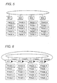
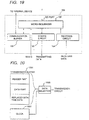
- FIG. 3 shows the circuit structure of the communication unit.
- the communication device 100 is structured by 1C.
- the reference numeral (101) denotes a micro-sequencer which controls data transmission/receiving in accordance to the invention and (102) a communication buffer for storing the transmitted/received data.
- a received data storage area of the communication buffer 102 is divided into a plurality of areas and the divided area is correlated with an identification number (ID) of the plurality of nodes 10 connected to the LAN in advance.
- ID identification number
- the present embodiment is characterized in a novelty that all nodes share data as the communication device of each node 10 receives the data transmitted to the other node 10.
- Table 1 shows one example of the storage area of the communication data buffer 102.
- the node ID is 1E and a data storage area corresponding to this ID (own ID) becomes an area for storing the transmission data.
- the received data is stored temporarily in a temporary buffer and is stored in a storage area corresponding to a node ID indicated by transmission originator data indicated by the received data after ending verification (error check, described later) of the received data.
- the IDs may be put in order in a predetermined manner. Although the order is not limited to be ascending or descending order, it is easiest to control the communication by the ascending order.
- the reference numeral (103) denotes a coding circuit for coding data to be transmitted to the other nodes 10 by the CMI coding method and (104) a decoding circuit for decoding the received data by the CMI decoding method.
- a signal MAXID indicates a maximum node ID value on the network and allows to know that the own node ID is the largest among the connected nodes 10 when the maximum node ID value coincides with own ID.
- This signal may be generated by a dip switch or the like.
- FIG. 4 shows a communication format of data transmitted in a mode of packet from the nodes.
- Alert is data positioned at the head of the packet and functions as a synchronizing signal.
- SID is source ID (ID of the transmission originator).
- DID is ID of the destination of transmission.
- CP is data specifying data size.
- DATA0 through DATAN is data to be transmitted. N bytes data is transferred in this example.
- CRC is an error check code for cycle redundancy check (CRC).
- the micro-sequencer 101 of the communication device in the node 10 connected to the LAN receives the transmission data on the LAN, stores it temporarily in the temporary buffer in the communication buffer 102 and then checks errors of the data 0 through data N by using the CRC data within the received data. When no error is detected, the micro-sequencer 101 judges that from which the received data is sent based on the SID data within the received data and stores it in a corresponding storage area within the communication buffer 102.
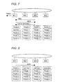
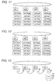
- FIG. 5 through 12 show processes for transmitting data from each node 10 by means of token passing and the storage contents in the communication buffer 102 of each node 10.
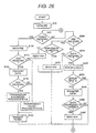
- FIG. 26 shows a communication control procedure executed by the micro-sequencer 101 of each node. It is noted that the control procedure is described by a program language which can be executed by the micro-sequencer (CPU) 101 and is stored in a ROM (not shown) within the micro-sequencer 101.
- CPU micro-sequencer
- Step S10 in FIG. 26 When power is put in each node and the initialization process is finished in such system structure (Step S10 in FIG. 26), the token is circulated as shown in FIG. 6 and the data transmission right is circulated.
- the internal device writes data 01 to be transmitted to Page 1 within the communication buffer 102 (own transmitting buffer) (see FIG. 7).
- the micro-sequencer 101 creates transmission data having the format in FIG. 4 by using this written data and waits to receive the token (the loop process of Steps S20 ⁇ S200 ⁇ S210 ⁇ S20 in FIG. 26).
- the node whose ID is #01 (the micro-sequencer 101) transmits a query FBE to Node #3 to which the data is to be sent (Steps S20 ⁇ S100 in FIG. 26).
- Node #03 (the micro-sequencer 101) is ready to receive, it gives a receiving authorizing ACK indicative of that (see FIG. 7. Steps S200 ⁇ S270 in FIG. 26).
- Receiving the ACK Node #01 transmits DATA 01 stored in Page 1 of own communication buffer 102 to Node #3 in accordance to the data format in FIG. 4 (Steps S110 ⁇ S120 in FIG. 26).
- Nodes #02 through #4 store it within the temporary buffer within the communication buffer 101 (Page 0, see FIG. 8).
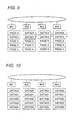
- the micro-sequencer 101 checks errors in the data stored in the temporary buffer (Steps S20 ⁇ S200 ⁇ S210 ⁇ S220 in FIG. 26). Then, after verifying that there is no error in the data, the micro-sequencer 101 of each node transfers and stores the received data DATA 01 stored in the temporary buffer to the storage area corresponding to the transmission originator, i.e., in Page 1 in this case (see FIG. 9. Steps S230 ⁇ S240 in FIG. 26).
- the token is passed to the next node #02 after waiting data receiving ACK from Node #03 of the transmission destination (Steps S130 ⁇ S140 ⁇ S20 in FIG. 26 as for Node #01, Steps S250 ⁇ S260 ⁇ S20 as for Node #03, and Steps S250 ⁇ S20 as for the other nodes) .
- Node #02 also carries out processes similar to those in Node #01 described above and transmits DATA 02 to the other node.
- the similar transmission process is carried out thereafter to Node #04, the data of same contents is stored in the communication buffer of respective Nodes #01 through #04 as shown in FIG. 10. Therefore, all of the nodes can share the data.
- each Node detects that an error has occurred by checking the data. Accordingly, the data in the temporary buffer is not transferred to the corresponding storage area (see FIG. 12, Steps S230 ⁇ S20 in FIG. 26).
- Node #01 also does not transmit ACK data indicative of that the data has been received normally to Node #04. Thereby, Node #04 detects that the communication error has occurred. Detecting the transmission error, Node #04 may transmit DATA 4a again when the token comes in the next time or may transmits the latest data DATA 04b when DATA04b is generated as data to be transmitted anew.
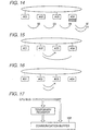
- Each node detects ID of the adjoining node while incrementing ID of the node to which the token is to be passed in the initializing process to discriminate the ID of the adjoining node to which the token is to be passed in the conventional token passing communication method, for example, called as ARCNET (the token does not circulate when ID of non-connected node is set as a destination to which the token is passed. Thereby, it can be found that the node of ID thus set is a non-connected node. See FIG. 13). Accordingly, it takes time for each node to detect ID of the adjoining node.
- the node whose own ID coincides with the MAX ID initializes a node ID to which the token is to be passed at #01.
- a node whose own ID does not coincide with MAX ID initializes a node to which the token is to be passed at ID which is incremented by +1 from own ID (see FIG. 14).
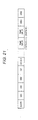
- FIG. 27 shows the sequence of the initializing process carried out by the micro-sequencer 101 for reference.
- Step S400 is a process executed by the micro-sequencer of a node whose own ID does not coincide with MAX ID.
- Step S410 is a process executed by the micro-sequencer of a node to which MAX ID has been inputted.
- Step S420 is an initializing process similar to the past one executed in common.
- the token is passed to the adjoining node in the prior art token passing communication method like ARCNET.
- own node increments (by +1) ID of a node to which the token is to be passed to find the node to which the token is to be passed. Therefore, there has been a problem that the adjoining node does not react at all when the token is not transmitted normally due to noises and others even when the adjoining node is actually connected to LAN and the token is passed to the next node in disregard of the original node to which the token is to be passed. Then, the token passing is carried out by a plurality of times when no reaction is obtained as shown in FIG. 16 in the present embodiment.
- a maximum number of times of token passing N is set in advance and the micro-sequencer 101 executes the processing procedure in FIG. 28.
- the micro-sequencer 101 can obtain no reaction (NO in Steps S500 ⁇ S510 in FIG. 28) in transmitting the token (Step S140 in FIG. 26), it repeats the token passing process up to the maximum N times (a loop process from Step S501 ⁇ S502 ⁇ S500 ⁇ S510).
- the token passing process ends.
- the process for detecting the adjoining node is carried out after the alarming process as a matter of course.
- the communication device (LSI communication controller) 100 in FIG. 3 is connected to a device to be controlled, e.g., a controller (CPU) and the like for controlling a brake, via a CPU bus and transfers data received from the controller to the other nodes via LAN. It also passes data received from the other node to the controller.
- a device to be controlled e.g., a controller (CPU) and the like for controlling a brake
- CPU central processing unit
- a 16-bit CPU must be used on the side of controller.
- an 8-bit CPU is used on the side of controller.
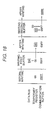
- a temporary register is provided between the controller (internal device in FIG. 3) and the communication buffer 102 as shown in FIG. 17.
- a timing signal generating circuit not shown generates a latch command signal so as to hold (latch) 8-bit data of the first time sent from the controller in the temporary register, to create 16-bit data by data directly sent from the controller and the data latched in the temporary register and to generate a write signal to write it into the communication buffer 102 (see FIG. 18).
- the temporary register may be also disabled (the timing signal generating circuit generates no latch command signal). In this case, a binary signal indicative of using/not using the temporary register is given to the timing signal generating circuit from the outside so that it generates an adequate latch command signal and write signal in correspondence to this command.
- the internal device such as the controller writes the transmission data to the communication buffer 102 and the micro-sequencer 101 reads the transmission data to transmit to the other node as shown in FIG. 3 in the embodiment described above.
- a command whether to use or not use the communication buffer 102 is given to the micro-sequencer 101 from the outside to initialize by the micro-sequencer 101 whether data is to be taken in via the I/O port or via the communication buffer 102.
- FIG. 20 shows a circuit structure for that end.
- a transmission buffer 101 for creating transmission data is provided within a memory of the micro-sequencer 101.
- the reference numeral (1002) denotes a clock.
- the micro-sequencer 101 creates transmission data by combining the remaining data with the clock information obtained from the clock 1002 without using the data in the storage area corresponding to the clock data.
- the micro-sequencer 101 functions as a data selecting circuit 1003 in this case. Thereby, the clock data at the moment of transmission may be sent on the network.
- a clock master informing of reference time is set in advance among the nodes connected to LAN as shown in FIG. 22 so that the node of the clock master informs of the clock information to the other nodes.
- the node controls the internal clock so as to be synchronized with the received reference clock data by the micro-sequencer 101 as shown in FIG. 23. Because the internal clock is normally realized by means of counting process of hard process, a value of the counter is updated. It is noted that time may be synchronized by carrying out the following process when it is a problematic to return the clock to the past like a control of a vehicle.
- the reference clock data received from the clock master is compared with clock data indicated by the internal clock as shown in FIG. 23.
- the rate of the internal clock is advanced or retarded slightly or is kept as it is based on the difference.
- the internal clock may be synchronized with the reference clock during the normal operation.
- the clocks of all nodes indicate almost the same time with the time of the clock master by giving such time controlling function to each node.
- FIG. 24 shows a communication device which receives data without CPU.
- the reference numeral (2001) denotes a receiving buffer for receiving data on LAN.
- the node 10 to which the token has been passed transmits the same data twice in the embodiment.
- the reference numeral (2002) denotes a comparator for comparing whether or not two transmission data m and n received by the receiving buffer 2001 coincide.
- the reference numeral (2003) denotes a latch circuit such as a flip-flop for latching either one of the data m or n and for outputting the latched data via a port as receiving data when they coincide by the comparator 2002.
- Such circuit structure allows data to be received and an error check to be carried out by the simple arrangement without the data verification carried out by the CPU by multiplexing data, in addition to an error check code.
- the receiving buffer may receive only data addressed to it or receive all transferred data on LAN.
- packet data transferred among the respective nodes has the CRC error check code in ARCNET known as a communication protocol for a vehicular control system, that data cannot be used if the data is destroyed even by 1 bit due to spike noise and the like.
- the transfer data is coded in CMI in the embodiment described above in addition to adding the error check code to the transfer data.
- the CMI coding may be defined in four states and 1 bit is represented by two symbols as shown in FIG. 25.
- the possible state of a value is defined from the state of a previous signal in the CMI coding method, so that when a symbol not corresponding to that is received, it is judged that an error has occurred during transmission and the error may be corrected automatically.
- the receiving symbol when the receiving symbol is 11010100, the data indicates "1001".
- the receiving symbol when a communication error occurs and the receiving symbol becomes 1101 [11]00 (data surrounded by parentheses is the place where the error has occurred), the part in the parentheses 11 is impossible symbol.
- a possible symbol after 1101 is 01 or 00 and the symbol 01 having Hamming distance closest to 11 is set as a corrected value. No CRC error occurs even when the micro-sequencer 101 makes CRC check because such automatic data correcting process is carried out by the decoding circuit 104 (see FIG. 3) before inputting the receiving data to the micro-sequencer 101.
- each node stores data addressed to other node in connection with the node of the transmission originator, so that all of the nodes can share the whole data transmitted when the token circulates all of the nodes once.
- the sharing of data allows the plurality of nodes to execute control processes in cooperation and synchronism. Thereby, the reliability of the whole system may be enhanced.
- the correspondence between the storage area and ID of the node may be simplified, the storage address in the storage area may be simply led from ID of the node and the storage may be controlled (control for reading/writing data) readily by assigning data to the storage area corresponding to own node.
- data may be transmitted directly without going through the storage unit which realizes the function as a communication buffer and a multiplex communication device may be connected to a device generating transmission data whose communication specification is different, e.g., to a device which is unable to write data to the storage unit.
- each node is not required to have a process for automatically retrieving an adjoining node by specifying the last node.
- error-free data is stored in the storage area of the storage unit by temporarily storing the received data in the temporary buffer. Therefore, it is possible to block an erroneous control from being made and to keep the safety of the whole system even if a device making a control by using the receiving data reads the receiving data of the storage unit to make a control.
- the state of communication will not confuse even if a number of nodes receive data because the node at the transmission destination confirms the receiving.
- data errors which can be recovered increase and a number of times of re-transmission of data due to data error decreases, thus shortening the communication time, by CMI-coding the data containing the data check code.
- the reliability on the token communication is enhanced by giving the token re-transmission function to the nodes.
- the clocks of the transmission originator and the transmission destination may be controlled so that they indicate the same time based on clock information by adding the clock information to the transfer data.
- the invention may be used as a LAN communication system of a multi-use system because it allows modes of adding/not adding the clock information to be selected.
- the double data error check functions may be added to the node by additionally using the CRC code and the like and a communication system having a high data reliability may be constructed.
- the 15th aspect of the invention it is possible to connect with both external units using an 8-bit CPU and a 16-bit CPU by allowing data having a different bit number to be inputted.
- the invention brings about the maximum effect in use in a vehicle by applying the feature in the 16th, the 17th, the 19th, the 20th, the 22nd, and the 23rd aspect of the invention to the vehicular control system.
- transmission of information of a specific node will not be delayed extremely by using the communication protocol having no priority in the node-to-node communication.
Landscapes
- Engineering & Computer Science (AREA)
- Computer Networks & Wireless Communication (AREA)
- Signal Processing (AREA)
- Small-Scale Networks (AREA)
- Computer And Data Communications (AREA)
Applications Claiming Priority (2)
| Application Number | Priority Date | Filing Date | Title |
|---|---|---|---|
| JP2000033980A JP2001223726A (ja) | 2000-02-10 | 2000-02-10 | 多重通信方法、多重通信装置および多重通信システム |
| JP2000033980 | 2000-02-10 |
Publications (1)
| Publication Number | Publication Date |
|---|---|
| EP1124354A2 true EP1124354A2 (de) | 2001-08-16 |
Family
ID=18558390
Family Applications (1)
| Application Number | Title | Priority Date | Filing Date |
|---|---|---|---|
| EP00115303A Withdrawn EP1124354A2 (de) | 2000-02-10 | 2000-07-14 | Multiplex-Kommunikationsverfahren, Vorrichtung und System |
Country Status (3)
| Country | Link |
|---|---|
| US (1) | US6987776B1 (de) |
| EP (1) | EP1124354A2 (de) |
| JP (1) | JP2001223726A (de) |
Cited By (1)
| Publication number | Priority date | Publication date | Assignee | Title |
|---|---|---|---|---|
| DE112010002652B4 (de) * | 2009-03-25 | 2015-12-03 | Kabushiki Kaisha Toshiba | Übertragungssystem für Wagons |
Families Citing this family (8)
| Publication number | Priority date | Publication date | Assignee | Title |
|---|---|---|---|---|
| JP4645505B2 (ja) * | 2006-03-31 | 2011-03-09 | 株式会社デンソー | データ処理装置、及びプログラム |
| JP4411328B2 (ja) | 2007-02-01 | 2010-02-10 | 株式会社日立製作所 | データ通信システム及びデータ通信方法 |
| JP5308802B2 (ja) * | 2008-12-16 | 2013-10-09 | ルネサスエレクトロニクス株式会社 | Canノード |
| JP4888741B2 (ja) | 2009-02-05 | 2012-02-29 | 横河電機株式会社 | 分散型制御システム |
| AU2023246772A1 (en) | 2022-03-29 | 2024-01-18 | Illumina Inc. | Chromenoquinoline dyes and uses in sequencing |
| EP4735636A1 (de) | 2023-06-30 | 2026-05-06 | Illumina, Inc. | Systeme und verfahren zur sequenzierung von polynukleotiden mit vier markierten nukleotiden |
| EP4735635A1 (de) | 2023-06-30 | 2026-05-06 | Illumina, Inc. | Systeme und verfahren zur sequenzierung von polynukleotiden mit alternativen scatterplots |
| EP4735634A1 (de) | 2023-06-30 | 2026-05-06 | Illumina, Inc. | Systeme und verfahren zur sequenzierung von polynukleotiden mit modifizierten basen |
Family Cites Families (14)
| Publication number | Priority date | Publication date | Assignee | Title |
|---|---|---|---|---|
| JPS6014548A (ja) * | 1983-07-05 | 1985-01-25 | Canon Inc | 網制御方式 |
| JPS61253945A (ja) * | 1985-05-07 | 1986-11-11 | Canon Inc | 網制御方式 |
| US5253252A (en) * | 1989-01-10 | 1993-10-12 | The Foxboro Company | Token device for distributed time scheduling in a data processing system |
| US5241543A (en) * | 1989-01-25 | 1993-08-31 | Hitachi, Ltd. | Independent clocking local area network and nodes used for the same |
| JP2740031B2 (ja) * | 1990-01-05 | 1998-04-15 | 株式会社東芝 | データ受信装置 |
| JPH03266542A (ja) * | 1990-03-16 | 1991-11-27 | Toshiba Corp | 時刻同期方式 |
| JP2816016B2 (ja) * | 1990-10-31 | 1998-10-27 | 株式会社東芝 | スキャン伝送方式 |
| JP2920441B2 (ja) * | 1992-03-10 | 1999-07-19 | 株式会社日立製作所 | プロセスデータ処理システムおよび処理方法 |
| JP3314438B2 (ja) * | 1993-02-22 | 2002-08-12 | 株式会社日立製作所 | データ通信装置 |
| GB9313020D0 (en) * | 1993-06-24 | 1993-08-11 | Madge Networks Ltd | Jitter monitoring |
| US5566180A (en) * | 1994-12-21 | 1996-10-15 | Hewlett-Packard Company | Method for recognizing events and synchronizing clocks |
| EP0855818B1 (de) * | 1997-01-24 | 2005-03-23 | Matsushita Electric Industrial Co., Ltd. | Zuweisung und dynamische Anpassung von zweiten, nicht eindeutigen Kennzeichnungen für isochrone Kommunikationen an eine Vielzahl von Stationen mittels asynchronischer Kommunikation |
| US6700899B1 (en) * | 1998-02-03 | 2004-03-02 | Broadcom Corporation | Bit slice arbiter |
| US6426962B1 (en) * | 1998-06-24 | 2002-07-30 | International Business Machines Corporation | Token ring jitter generator/detector |
-
2000
- 2000-02-10 JP JP2000033980A patent/JP2001223726A/ja active Pending
- 2000-07-13 US US09/615,777 patent/US6987776B1/en not_active Expired - Fee Related
- 2000-07-14 EP EP00115303A patent/EP1124354A2/de not_active Withdrawn
Cited By (1)
| Publication number | Priority date | Publication date | Assignee | Title |
|---|---|---|---|---|
| DE112010002652B4 (de) * | 2009-03-25 | 2015-12-03 | Kabushiki Kaisha Toshiba | Übertragungssystem für Wagons |
Also Published As
| Publication number | Publication date |
|---|---|
| US6987776B1 (en) | 2006-01-17 |
| JP2001223726A (ja) | 2001-08-17 |
Similar Documents
| Publication | Publication Date | Title |
|---|---|---|
| US7783808B2 (en) | Embedded self-checking asynchronous pipelined enforcement (escape) | |
| EP0507579B1 (de) | Multiplexübertragung zwischen Knoten mit Berechnung der zyklischen Blockprüfung | |
| EP1022877B1 (de) | Verfahren zur Übertragung von Daten | |
| US5001642A (en) | Method for operating a data processing system | |
| US4764862A (en) | Resilient bus system | |
| US8665882B2 (en) | Serialized enforced authenticated controller area network | |
| RU2596582C2 (ru) | Способ и устройство для адаптируемой к размерам памяти последовательной передачи данных | |
| US6167057A (en) | Data communication system and electronic control unit used therein | |
| EP0076880A1 (de) | Lokales Netz mit Konkurrenzbetrieb für Datenkommunikationssysteme | |
| US5128936A (en) | Communication bus system and station for use in such a communication bus system | |
| EP1124354A2 (de) | Multiplex-Kommunikationsverfahren, Vorrichtung und System | |
| US20030226065A1 (en) | Controller area network controller for making a self-diagnosis of a function | |
| US5293571A (en) | Receipt acknowledgement method in multiplex transmission | |
| JP3516451B2 (ja) | 通信バスシステムとかかるシステムで使用されるステーション | |
| US4910732A (en) | Onechip-computers as network-controller and computer | |
| CN1113397A (zh) | 能缓和从站锁定问题的通信总线系统 | |
| US5249182A (en) | Communication bus system with lock/unlock capability | |
| US6771716B1 (en) | Method of communication with coherence checking and device for the implementation thereof | |
| JP2000165424A (ja) | ループ式データ伝送装置 | |
| JP2989917B2 (ja) | 多重伝送方式 | |
| JPH05316125A (ja) | シリアル多重通信システム | |
| JPS63267039A (ja) | ネツトワ−クシステム | |
| JPS6336025B2 (de) | ||
| JPH0191552A (ja) | データ伝送装置 | |
| JPH0537570A (ja) | 通信制御回路の受信データ格納方法 |
Legal Events
| Date | Code | Title | Description |
|---|---|---|---|
| PUAI | Public reference made under article 153(3) epc to a published international application that has entered the european phase |
Free format text: ORIGINAL CODE: 0009012 |
|
| AK | Designated contracting states |
Kind code of ref document: A2 Designated state(s): AT BE CH CY DE DK ES FI FR GB GR IE IT LI LU MC NL PT SE |
|
| AX | Request for extension of the european patent |
Free format text: AL;LT;LV;MK;RO;SI |
|
| STAA | Information on the status of an ep patent application or granted ep patent |
Free format text: STATUS: THE APPLICATION HAS BEEN WITHDRAWN |
|
| 18W | Application withdrawn |
Effective date: 20050722 |