EP1124380B1 - Méthode de traitement d'images - Google Patents
Méthode de traitement d'images Download PDFInfo
- Publication number
- EP1124380B1 EP1124380B1 EP01104611A EP01104611A EP1124380B1 EP 1124380 B1 EP1124380 B1 EP 1124380B1 EP 01104611 A EP01104611 A EP 01104611A EP 01104611 A EP01104611 A EP 01104611A EP 1124380 B1 EP1124380 B1 EP 1124380B1
- Authority
- EP
- European Patent Office
- Prior art keywords
- dct
- subblock
- block
- target
- prediction
- Prior art date
- Legal status (The legal status is an assumption and is not a legal conclusion. Google has not performed a legal analysis and makes no representation as to the accuracy of the status listed.)
- Expired - Lifetime
Links
Images






Classifications
-
- H—ELECTRICITY
- H04—ELECTRIC COMMUNICATION TECHNIQUE
- H04N—PICTORIAL COMMUNICATION, e.g. TELEVISION
- H04N19/00—Methods or arrangements for coding, decoding, compressing or decompressing digital video signals
- H04N19/50—Methods or arrangements for coding, decoding, compressing or decompressing digital video signals using predictive coding
- H04N19/503—Methods or arrangements for coding, decoding, compressing or decompressing digital video signals using predictive coding involving temporal prediction
- H04N19/51—Motion estimation or motion compensation
-
- H—ELECTRICITY
- H04—ELECTRIC COMMUNICATION TECHNIQUE
- H04N—PICTORIAL COMMUNICATION, e.g. TELEVISION
- H04N19/00—Methods or arrangements for coding, decoding, compressing or decompressing digital video signals
- H04N19/10—Methods or arrangements for coding, decoding, compressing or decompressing digital video signals using adaptive coding
- H04N19/169—Methods or arrangements for coding, decoding, compressing or decompressing digital video signals using adaptive coding characterised by the coding unit, i.e. the structural portion or semantic portion of the video signal being the object or the subject of the adaptive coding
- H04N19/18—Methods or arrangements for coding, decoding, compressing or decompressing digital video signals using adaptive coding characterised by the coding unit, i.e. the structural portion or semantic portion of the video signal being the object or the subject of the adaptive coding the unit being a set of transform coefficients
-
- H—ELECTRICITY
- H04—ELECTRIC COMMUNICATION TECHNIQUE
- H04N—PICTORIAL COMMUNICATION, e.g. TELEVISION
- H04N19/00—Methods or arrangements for coding, decoding, compressing or decompressing digital video signals
- H04N19/10—Methods or arrangements for coding, decoding, compressing or decompressing digital video signals using adaptive coding
- H04N19/102—Methods or arrangements for coding, decoding, compressing or decompressing digital video signals using adaptive coding characterised by the element, parameter or selection affected or controlled by the adaptive coding
- H04N19/103—Selection of coding mode or of prediction mode
- H04N19/105—Selection of the reference unit for prediction within a chosen coding or prediction mode, e.g. adaptive choice of position and number of pixels used for prediction
-
- H—ELECTRICITY
- H04—ELECTRIC COMMUNICATION TECHNIQUE
- H04N—PICTORIAL COMMUNICATION, e.g. TELEVISION
- H04N19/00—Methods or arrangements for coding, decoding, compressing or decompressing digital video signals
- H04N19/10—Methods or arrangements for coding, decoding, compressing or decompressing digital video signals using adaptive coding
- H04N19/102—Methods or arrangements for coding, decoding, compressing or decompressing digital video signals using adaptive coding characterised by the element, parameter or selection affected or controlled by the adaptive coding
- H04N19/103—Selection of coding mode or of prediction mode
- H04N19/112—Selection of coding mode or of prediction mode according to a given display mode, e.g. for interlaced or progressive display mode
-
- H—ELECTRICITY
- H04—ELECTRIC COMMUNICATION TECHNIQUE
- H04N—PICTORIAL COMMUNICATION, e.g. TELEVISION
- H04N19/00—Methods or arrangements for coding, decoding, compressing or decompressing digital video signals
- H04N19/10—Methods or arrangements for coding, decoding, compressing or decompressing digital video signals using adaptive coding
- H04N19/134—Methods or arrangements for coding, decoding, compressing or decompressing digital video signals using adaptive coding characterised by the element, parameter or criterion affecting or controlling the adaptive coding
- H04N19/136—Incoming video signal characteristics or properties
- H04N19/14—Coding unit complexity, e.g. amount of activity or edge presence estimation
-
- H—ELECTRICITY
- H04—ELECTRIC COMMUNICATION TECHNIQUE
- H04N—PICTORIAL COMMUNICATION, e.g. TELEVISION
- H04N19/00—Methods or arrangements for coding, decoding, compressing or decompressing digital video signals
- H04N19/10—Methods or arrangements for coding, decoding, compressing or decompressing digital video signals using adaptive coding
- H04N19/134—Methods or arrangements for coding, decoding, compressing or decompressing digital video signals using adaptive coding characterised by the element, parameter or criterion affecting or controlling the adaptive coding
- H04N19/157—Assigned coding mode, i.e. the coding mode being predefined or preselected to be further used for selection of another element or parameter
- H04N19/16—Assigned coding mode, i.e. the coding mode being predefined or preselected to be further used for selection of another element or parameter for a given display mode, e.g. for interlaced or progressive display mode
-
- H—ELECTRICITY
- H04—ELECTRIC COMMUNICATION TECHNIQUE
- H04N—PICTORIAL COMMUNICATION, e.g. TELEVISION
- H04N19/00—Methods or arrangements for coding, decoding, compressing or decompressing digital video signals
- H04N19/10—Methods or arrangements for coding, decoding, compressing or decompressing digital video signals using adaptive coding
- H04N19/169—Methods or arrangements for coding, decoding, compressing or decompressing digital video signals using adaptive coding characterised by the coding unit, i.e. the structural portion or semantic portion of the video signal being the object or the subject of the adaptive coding
- H04N19/17—Methods or arrangements for coding, decoding, compressing or decompressing digital video signals using adaptive coding characterised by the coding unit, i.e. the structural portion or semantic portion of the video signal being the object or the subject of the adaptive coding the unit being an image region, e.g. an object
- H04N19/176—Methods or arrangements for coding, decoding, compressing or decompressing digital video signals using adaptive coding characterised by the coding unit, i.e. the structural portion or semantic portion of the video signal being the object or the subject of the adaptive coding the unit being an image region, e.g. an object the region being a block, e.g. a macroblock
-
- H—ELECTRICITY
- H04—ELECTRIC COMMUNICATION TECHNIQUE
- H04N—PICTORIAL COMMUNICATION, e.g. TELEVISION
- H04N19/00—Methods or arrangements for coding, decoding, compressing or decompressing digital video signals
- H04N19/50—Methods or arrangements for coding, decoding, compressing or decompressing digital video signals using predictive coding
- H04N19/593—Methods or arrangements for coding, decoding, compressing or decompressing digital video signals using predictive coding involving spatial prediction techniques
-
- H—ELECTRICITY
- H04—ELECTRIC COMMUNICATION TECHNIQUE
- H04N—PICTORIAL COMMUNICATION, e.g. TELEVISION
- H04N19/00—Methods or arrangements for coding, decoding, compressing or decompressing digital video signals
- H04N19/60—Methods or arrangements for coding, decoding, compressing or decompressing digital video signals using transform coding
-
- H—ELECTRICITY
- H04—ELECTRIC COMMUNICATION TECHNIQUE
- H04N—PICTORIAL COMMUNICATION, e.g. TELEVISION
- H04N19/00—Methods or arrangements for coding, decoding, compressing or decompressing digital video signals
- H04N19/60—Methods or arrangements for coding, decoding, compressing or decompressing digital video signals using transform coding
- H04N19/61—Methods or arrangements for coding, decoding, compressing or decompressing digital video signals using transform coding in combination with predictive coding
Definitions
- the present invention relates to an image processing method in which adaptive intra-frame prediction is performed to frequency components of an interlaced image signal, thereby improving efficiency in coding of an image signal.
- Predictive coding which compresses image data of a moving picture using its redundancy, includes intra-frame predictive coding which predicts image data using image data in a target frame to-be-coded thereinafter referred to as a target frame), and inter-frame predictive coding which predicts image data using image data in a frame other than the target frame.
- a prediction value of image data in a target frame is generated from the image data in the target frame, and a difference value between a value of the image data and the prediction value is coded, thereby eliminating or reducing a large amount of spatially redundant information inherent in image data, when compressing image data.
- a prediction value of image data in a target frame is generated from data in another frame, and a difference value between a value of the image data and the prediction value is coded, thereby eliminating or reducing a large amount of temporarily redundant information included in image data of an image in small motion, when compressing image data.
- DCT Discrete Cosine Transform
- MPEG Motion Picture Expert Group
- an image space (frame) formed by a digital image signal is divided into plural rectangular regions (blocks) as DCT units, and the DCT is performed to the image signal for each block.
- An intra-frame prediction method of DCT coefficients i.e., image data in a DCT domain (frequency domain) which is adopted by MPEG is described in "Intra DC and AC prediction for I-VOP and P-VOP" of ISO/IEC JTC1/SC29/WG11 MPEG97/Nl642 MFEG-4 Video verification Model version 7.0 (hereinafter referred to as MPEG-4 VM 7.0).
- a DC (direct current) component and AC (alternating current) components of DCT coefficients of a target block to-be-coded are predicted using DCT coefficients of three blocks positioned upper left, above, and left, with respect to and adjacently to the target block in an image space.
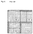
- Figure 15 is a diagram for explaining an intra-frame DCT coefficient prediction method described in the reference which is adopted by a prior art image coding method.
- DCT blocks DCT blocks
- X DCT units
- These blocks are positioned adjacently to each other in an image space (spatial domain) formed by an image signal.
- the block X is a target block
- the blocks R0, R1, and R2 are blocks which have been coded (hereinafter referred to as a coded clock), which are positioned upper left, above, and left, with respect to and adjacently to the target block in the spatial domain.
- prediction values of DCT coefficients of the block X are generated with reference to DCT coefficients of the block R1 or the block R2.
- DCT coefficients of the coded block R1 are referred to
- a DC component in the upper left corner and AC components in the highest row of the coded block R1 are used as prediction values of OCT coefficients positioned at the corresponding positions of the block X.
- DCT coefficients of the coded block R2 are referred to, a DC component in the upper left corner and AC components in the leftmost column of the coded block R2 are used as prediction values of DCT coefficients positioned at the corresponding positions of the block X.
- DCT frequency transformation
- frame DCT image data is transformed frame by frame
- field DCT image data is transformed field by field.
- switching between the frame DCT and the field DCT is adaptively performed for each macroblock comprising 4 blocks.
- DCT is performed to image data of each of 4 blocks of a macroblock in which scanning lines have been rearranged.
- CCT is performed to image cata of each of 4 blocks of a macroblock in which even-numbered scanning lines and odd-numbered scanning lines are alternately arranged.
- scanning lines are rearranged, and thereby a macroblock comprises a first field block comprising even-numbered scanning lines, and a second field block comprising odd-numbered scanning lines, followed by performing DCT to image data of each block of the macroblock,
- macroblocks to which the frame DCT is performed and macroblocks to which the field DCT is performed coexist in an image space.
- the frame DCT is performed, and in other cases, the field DCT is performed.
- DCT of neighboring macroblocks or adjacent blocks differ from each other.
- DCT coefficients there is correlation between adjacent macroblocks or blocks lower than in the case of using one type DCT.
- fields to which adjacent blocks belong differ from each other between these blocks. Also in such cases, with respect to DCT coefficients, there is correlation between adjacent blocks lower than in a case where the blocks belong to the same field.
- a method according to the invention is set out in claim 1.
- An image processing apparatus (image coding apparatus) and an image processing method (image coding method) according to a first embodiment of the present invention are characterized by performing infra-frame prediction coding of an image signal by employing an adaptive intra-frame DCT coefficient prediction method, i.e., a method of generating prediction values of DCT coefficients of a block to be coded (a target block) from DCT coefficients cf a block which has already been coded, according to a DCT type signal (frequency transformation type signal) of the coded block.
- the DCT type signal is a signal showing whether the target block has been processed by frame DCT or field DCT.
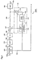
- Figure 1 is a block diagram illustrating an image coding apparatus according to the first embodiment.
- reference numeral 1000 designates an image coding apparatus, wherein an input digital image signal (input image signal) 110a is divided into plural image signals corresponding to plural blocks into which an image space (frame) formed by the digital image signal 110a is divided, and these image signals corresponding to the respective blocks are coded block by block.
- the image coding apparatus 1000 includes a blocking unit 100 which divides the input image signal 110a into plural image signals corresponding to the respective blocks mentioned above for each frame cr field (a processing unit of frequency transformation), and outputs the image signals 101 of the respective blocks and a DCT type signal 102 showing the processing unit of the frequency transformation (DCT).
- the blocking unit 100 receives the input image signal 100a and, when the correlation of pixel values between fields is higher than the correlation of pixel values within a frame, the blocking unit 100 performs rearrangement of scanning lines for each macroblock comprising 16 ⁇ 16 pixels so that field DCT is executed, and outputs the image signal block by block, which block comprises 8 ⁇ 8 pixels and is a component of the macroblock subjected to the rearrangement of scanning lines.
- the blocking unit 100 when the correlation of pixel values between fields is lower than the correlation of pixel values within a frame, the above-described rearrangement of scanning lines for each macroblock is not carried out, and the input image signal is output block by block as mentioned above.
- the image coding apparatus 1000 includes a CCT unit 103 which subjects the blocked image signal 101 to DCT to transform it into frequency components (DCT coefficients) 104; a quantizer 105 which quantizes the DCT coefficients 104 to generate quantized values (quantized DCT coefficients) corresponding to each block; an infra-frame prediction unit 110 which generates prediction values 111 of a target block by intra-frame prediction on the basis of the CCT type signal 102; an adder 107 which subtracts the prediction values 111 from the quantized DCT coefficients 106 and outputs DCT coefficient difference values 108; and a variable-length coder (VLC) 109 which subjects the DCT coefficient difference values 108 to variable-length coding and outputs a bit stream (a coded image signal 110b).
- VLC variable-length coder
- the intra-frame prediction unit 110 comprises an adder 112 which adds the DCT coefficient difference values 108 and the intra-frame prediction values 111; a block memory 115 which stores the output from the adder 112 as quantized DCT coefficients 116 of the block which have been coded; and a DCT coefficient predictor 113 which generates prediction values 111 of quantized DCT coefficients of the target block from quantized DCT coefficients 114 of the ceded block, according to the DCT type signal 102, by the adaptive intra-frame DCT coefficient prediction method.
- the blocking unit 100 When a digital image signal (input image signal) 110a is input to the image coding apparatus 1000, in the blocking unit 100, the image signal 110a is divided into plural image signals corresponding to the respective blocks described above for each frame or field (a processing unit of frequency transformation), and the blocking unit 100 outputs the blocked image signal 101 and a DCT type signal 102 showing the processing unit of frequency transformation (DCT).
- DCT processing unit of frequency transformation
- the blocking unit 100 when the correlation of pixel values within a field is higher than the correlation of pixel values in a frame, the image signal is subjected to rearrangement of scanning lines for each macroblock comprising 16 ⁇ 16 pixels so that field DCT is executed, and the image signal in which the scanning lines have been rearranged is output block by block, which block comprises 8 ⁇ 8 pixels and is a component of the macroblock.
- the image signal 101 corresponding to a target block to be codec is transformed to frequency components (DCT coefficients) 104 of the target block by discrete cosine transform (DCT) in the DCT unit 103, and the DCT coefficients 104 are quantized by the quantizer 105 and outputted as quantized values (quantized DCT coefficients) 106 of the target block.
- DCT discrete cosine transform
- the quantized DCT coefficients 106 cf the target block are input to the adder 107, wherein difference values between the quantized values 106 and the prediction values 111 are obtained, and these difference values are output as DCT coefficient difference values 108.
- the DCT coefficient difference values 108 are subjected to variable-length coding in the VLC 109 and outputted as a bit stream (coded image signal) 110b.
- the DCT coefficient difference values 108 output from the adder 107 are input to the intra-frame prediction unit 110, wherein prediction values of the quantized DCT coefficients 106 are generated.
- the DCT coefficient difference values 108 and the intra-frame prediction values 111 are added by the adder 112, and the sums are stored in the block memory 115 as quantized DCT coefficients 110 of the coded block.
- the DCT coefficient predictor 113 prediction values 111 of the quantized DCT coefficients of the target block are generated from the quantized DCT coefficients 114 of the coded block, according to the DCT type signal 102, by the adoptive intra frame DCT coefficient prediction method.
- a DCT domain is defined as follows.
- a DCT domain is a domain comprising frequency components which are obtained by subjecting an image signal forming an image space (spatial domain) to DCT (frequency transformation).
- macroblocks are arranged in the same way as macroblocks are arranged in the spatial domain of the image signal (image space).
- frame prediction a block positioned diagonally to the upper left of a target block x(i) is a reference block r0(i)
- a block positioned above and adjacent to the target block x(i) is a reference block r1(i)
- a block positioned at the left of and adjacent to the target block x(i) is a reference block r2(i).
- the reference blocks r0(i), r1(i), and r2(i) are spatially nearest to the target block x(i) and, therefore, DCT coefficients of these reference blocks have high correlation with DCT coefficients of the target block x(i).
- field prediction a block positioned above and one-block spaced apart from a target block x(i) is a reference block r1(i)
- a block positioned at the left of and adjacent to the reference block r1(i) is a reference block r0(i)
- a block positioned at the left of and adjacent to the target block x(i) is a reference block r2(i).
- the reference blocks r0(i), r1(i), and r2(i) are spatially nearest to the target block x(i) in the same field and, therefore, DCT coefficients of these reference blocks have high correlation with DCT coefficients cf the target block x(i).
- figure 5 is a flowchart showing the procedure of the adaptive intra frame DCT coefficient prediction method.
- step 51 the DCT type of the target block x(i) tc be coded is decided. The following steps depend on the result of this decision.
- step S52 frame prediction is carried out using the reference blocks r0(i), r1(i), and r2(i) for the target block x(i) shown in figure 4(a), thereby to generate prediction, values of DCT coefficients of the target block x(i).
- step S53 field prediction is carried out using the reference blocks r0(i), r1(i), and r2(i) for the target block x(i) shown in figure 4(b), thereby to generate prediction values of DCT coefficients of the target block x(i).
- the reference blocks used for prediction are selected according to the DCT type of the target block x(i)
- DCT coefficients of reference blocks having high correlation with DCT coefficients of the target block x(i) are used for prediction, resulting in highly-efficient prediction.
- r0(i), r1(i), r2(i) and x(i) denote the reference blocks and the target block shown in figure (a), respectively.
- reference blocks processed by frame DCT i.e., those having the same DCT type as the target block x(i), are used for prediction with priority.
- step S611a the DCT type of the reference block r2(i) at the left cf the target block x(i) is decided. The following steps depend on the result of this decision.
- steps S612a and S613a the DCT type of the reference block r1(i) above the target block x(i) is decided. The following steps depend on the result of this decision, according to the DCT types of the reference blocks r1(i) and r2(i), the frame prediction shown in figure 6 is divided into four process steps (A1) ⁇ (A4) as follows.
- step S614a When both of the reference blocks r1(i) and r2(i) have been processed by frame DCT, in step S614a, with reference to the DCT coefficients of the reference blocks r0(i), r1(i), and r2(i), prediction values of DCT coefficients of the target block x(i) are generated by "Method 1" which is described later.
- step S619a prediction values of DCT coefficients of the target block x(i) are generated using the DCT coefficients of the reference block r2(i). This is similar to the conventional method already described with respect to figure 15, i.e., to generate prediction values of DCT coefficients of the block X from the DCT coefficients of block R2.
- step S616a prediction values of DCT coefficients of the target block x(i) are generated using the DCT coefficients of the reference block r1(i). This is similar to the conventional method already described with respect to figure 15, i.e., to generate prediction values of DCT coefficients of the block X from the DCT coefficients of block R1.
- step S617a With reference to the DCT coefficients of these reference blocks r0(i), r1(i), and r2(i) prediction values of the target block x(i) are generated by "Method 2" which is described later.
- step 5617a instead of referring to the DCT coefficients of the reference blocks r0(i) r1(i) and r2(i), a prescribed value, such as 0, may be used as a prediction value. Further, steps S613a and S617a may be dispensed with for simplification. In this case, when it is decided in step S611a that the reference block r2(i) has not been processed by frame DCT, prediction values of DCT coefficients of the target block x(i) are generated using the DCT coefficients of the reference block r1(i) in step S616a.
- r0(i), r1(i), r2(i) and x(i) denote the reference blocks and the target block shown in figure 4(b), respectively.
- reference blocks processed by field DCT i.e., these having the same DCT type as the target block x(i), are used for prediction with priority.
- step S711b the DCT type of the reference block. r2(i) at the left of the target block x(i) is decided. The following steps depend on the result of this decision.
- steps S712b and S713b the DCT type of the reference block r1 (i) above the target block x(i) is decided. The following steps depend on the result of this decision.
- the field prediction shown in figure 7 is divided into four process steps (B1)-(B4) as fellows.
- step S714b With reference to the DCT coefficients of the reference blocks r0(i), r1(i), and r2(i), prediction values of DCT coefficients of the target block x(i) are generated by "Method 1" which is described later.
- step S715b prediction values of DCT coefficients of the target block x(i) are generated using the DCT coefficients of the reference block r2(i). This is similar to the conventional method already described with respect to figure 15. i.e., to generate prediction values of CCT coefficients of the block X from the DCT coefficients cf block R2.
- step S716b prediction values of DCT coefficients of the target block x(i) are generated using the DCT coefficients of the reference block r1(i). This is similar to the conventional method already described with respect to figure 15, i.e., to generate prediction values of DCT coefficients of the block X from the DCT coefficients of block R1.
- step S717b When both of the reference blocks r1(i) and r2(i) have been processed by frame DCT, in step S717b, with reference to the DCT coefficients of the reference blocks r0(i), r1(i), and r2(i), prediction values of the target block x(i) are generated by "Method 2" which is described later.
- step S717b instead of referring to the OCT coefficients of the reference blocks r0(i), r1(i) and r2(i), a prescribed value, such as 0, may be used as a prediction value. Further, steps S713b and 5717b may be dispensed with for simplification. In this case, when the decision in step S711b is that the reference block r2(i) has not been processed by field DCT, prediction values of DCT coefficients of the target block x(i) are generated using the DCT coefficients of the reference block r1(i) in step S716b.
- a virtual memory space (a virtual buffer) for storing DCT coefficients of the four blocks shown in figure 15 is presumed, and the conventional DCT coefficient prediction method is applied to the respective blocks on the victual buffer.
- R0 R1, and R2 denote reference blocks on the virtual buffer
- DC0, DC1, and DC2 denote DC components of DCT coefficients of the reference blocks R0, R1, and R2, respectively.
- r0(i), r1(i), r2(i), and x(i) denote reference blocks and a target block having the positional relationships shown in figure 4(a).
- step S821a the DCT type of the reference block r0(i) is decided in step S821a, and the following process of generating DCT coefficients of the reference block R0 (step S822a or S823a) depends on the result cf the decision in step S821a.
- step S824a DCT coefficients are generated by a prescribed method from blocks in the vicinity of the reference block r0(i), and the DCT coefficients so generated are stored in the virtual buffer as DCT coefficients of the reference block R0.
- step S821a DCT coefficients of the reference block r0(i) are stored in the virtual buffer as DCT coefficients of the reference block R0 .
- DCT coefficients of the reference block R1 are generated in steps S824a, S825a, and S826a, and DCT coefficients of the reference block P2 are generated in steps S827a, S828a, and S329a. These DCT coefficients are stored in the virtual buffer.
- step S830a the absolute value of a difference in DC components of DCT coefficients between the reference block R0 and the reference block R1 (
- step S832a prediction values of DCT coefficients of the target block x(i) are generated using the DCT coefficients of the reference block R1.
- step S831a prediction values cf DCT coefficients of the target block x(i) are generated using the DCT coefficients of the reference block R2.
- steps S824a, S827a, S825a, and S828a shown in figure 8 can be dispensed with in this case.
- step S921b the DCT type of the reference block r0(i) is decided in step S921b, and the following process of generating DCT coefficients of the reference block R0 (step S922b or S923b) depends on the result of the decision in step S921b.
- step S922b DCT coefficients are generated by a prescribed method from blocks in the vicinity of the reference block r0(i), and the DCT coefficients so generated are stored in the virtual buffer as DCT coefficients of the reference block R0.
- step S923b DCT coefficients of the reference block r0(i) are stored in the virtual buffer as DCT coefficients of the reference block R0.
- DCT coefficients of the reference block R1 are generated in steps S924b, S525b, and S926b, and DCT coefficients of the reference block R2 are generated in steps S927b, S929b, and S929b. These DCT coefficients are stored in the virtual buffer.
- step S930b the absolute value of a difference in DC components of DCT coefficients between the reference block R0 and the reference block R1 (
- is smaller than
- step S932b prediction values of DCT coefficients of the target block x(i) are generated using the DCT coefficients of the reference block R1.
- step S931b prediction values of DCT coefficients of the target block x(i) are generated using the DCT coefficients of the reference block R2.
- step S714b shown in figure 7
- steps S924b, S927b, S925b, and S928b shown in figure 9 can be dispensed with in this case.
- the DCT coefficients cf this reference block are not referred to, but OCT coefficients having frequency characteristics similar to those of the DCT type of the target block are generated from blocks in the vicinity of the reference block, and DCT coefficients of the target block are predicted using the DCT coefficients so generated, whereby the prediction efficiency is improved.
- Figure 10 is a schematic diagram for explaining a method for generating DCT coefficients from blocks in the vicinity of a reference black r, in steps S822a, S825a, S828a shown in figure 8, and steps S922b, S925b, and S923b shown in figure 9.
- r denotes any of the reference blocks r0(i), r1(i), and r2(i) in the frequency domain
- R denotes any of the reference blocks R0, R1, and R2 on the victual buffer.
- DCT coefficients are generated using a prescribed function from DCT coefficients of two blocks in the vicinity of the reference block r as shown in figure 10, and the CCT coefficients so generated are used as DCT coefficients of the reference block R on the virtual buffer.
- Figure 11 is a flowchart showing the procedure of generating DCT coefficients of the reference block R on the virtual buffer. In figure 11, different processes are carried but according to the position of the reference block r in the macroblock in the DCT domain.
- DCT coefficients of the reference block R on the virtual buffer are generated using a prescribed function from DCT coefficients of blocks positioned in the areas (0) and (2) of the macroblock in the DCT domain, which areas include the reference blocks r.
- step S1142P DCT coefficients of the reference block R on the virtual buffer are generated using a prescribed function from DCT coefficients of blocks positioned in the areas (1) and (3) of the macroblock in the DCT domain, which areas include the reference blocks r.
- any function may be employed as long as, with the function, DCT coefficients of the reference block R on the virtual buffer can be uniquely calculated from DCT coefficients of two blocks in the vicinity of the reference block r, for example, a function in which averages or weighed averages of DCT coefficients between two blocks in the vicinity of the reference block r in the frequency domain are used as DCT coefficients of the reference block R on the virtual buffer.
- step S1143 the DCT coefficients generated with reference to the two blocks in the frequency domain are used as DCT coefficients of the reference block R on the virtual buffer.
- DCT coefficients of the reference block R in the virtual area used for prediction are generated from DCT coefficients of two blocks having information of the same area as the reference block r in the spatial domain, it is possible to generate DCT coefficients having frequency characteristics similar to those of DCT coefficients of the DCT type of the target block.
- reference blocks used for prediction are selected according to the DCT type of the target block, and CCT coefficients of reference blocks of the same DCT type as the target block are used for prediction with priority.
- DCT type of the reference block is different from that cf the target block, from DCT coefficients of blocks in the vicinity of the reference block, DCT coefficients of blocks, which have frequency characteristics similar to those of DCT coefficients of reference blocks having the same DCT type as the target block, arc generated for prediction. Therefore, intra-frame prediction for an interlaced image or a specific progressive image is efficiently performed in the DCT domain (frequency components).
- the efficiency of predicting DCT coefficients of a block to be coded is improved y using intra-frame information, it is possible to efficiently perform compressive coding of an image signal by removal or reduction, or spatially redundant image information.
- the DCT coefficients of the reference block r2(i) are used as prediction values of DCT coefficients of the target block x(i) (see figures 4(a) and 4(b))
- the DCT type of the reference block r2(i) is different from that of the target block x(i)
- only a DC component among the DCT coefficients of the reference block r2(i) may be used as a prediction value for the target block x(i).
- DCT coefficients of the reference block R (to be specific, reference blocks R0, R1, R2) on the virtual buffer used for prediction of DCT coefficients of the target block are generated from the DCT coefficients of the reference block r (to be specific, reference blocks r0(1), r1(i), r2(i)).
- DCT coefficients may be generated using a prescribed deviation from DCT coefficients of two blocks in the vicinity of the reference block r in the spatial domain to be specific, reference blocks r0(i), r1(i), r2(i), and the generated DCT coefficients may be used as DCT coefficients of the reference block E on the virtual buffer.
- one of the four processes 31-34 is carried out according to the DCT type of the reference block r2(i) at the lift of the target block x(i) and the DCT type of the reference block r1(i) above the target block x(i).
- B1, B3, and B4 may be replaced with the following processes B1', B3', and B4'.
- a coded block positioned just above the target block x(i) i . e., in figure 1(b)
- a coded block positioned between the target block x(i) and the coded block r1(i) is used as a reference block
- DCT coefficients of this reference block are used as prediction values of DCT coefficients of the target block.
- steps S922b and S923b the reference block r0(i) and a coded block positioned between the reference block r0(i) and the reference block r2(i) are subjected to weighted averaging at a weighting ratio of 0:1, thereby generating DCT coefficients of the reference block R0 on the virtual buffer.
- steps S925b and S926b the reference block r1(i) and a coded block positioned between the reference block r1(i) and the target block x(i) are subjected to weighted averaging at o weighting ratio of 0:1, thereby generating DCT coefficients of the reference block R1 on the virtual buffer.
- the reference block r2(i) and a coded block positioned between the reference block r2(i) and the reference block r0 (i) are subjected to weighted averaging at a weighting ratio of 1:0, thereby generating DCT coefficients of the reference block R1 on the virtual buffer.
- the processes B1' and B4' it is presumed that the positions of the respective blocks r0(i) ⁇ r2(i) relative to the target block x(i) are as shown in figure 4(b).
- weighted averaging between the reference block r0(i) and a coded block just beneath the reference block r0(i) is carried out with a weighting ratio of 1 for one of these blocks nearer to the target block x(i)
- weighted averaging between the reference block r1(i) and a coded block just beneath the reference block r1(i) is carried out with a weighting ratio of 1 for one of these blocks nearer to the target block x(i)
- weighted averaging between the reference block r2(i) and a coded block just above the reference block r2(i) is carried cut with a weighting ratio of 1 for one of these blocks nearer to the target block x(i).
- An image processing apparatus (image decoding apparatus) and an image decoding method (image decoding method) according to a second embodiment of the present invention are characterized by that decoding of a coded image signal is performed using the adaptive infra-frame DCT coefficients prediction method which is used for the image coding apparatus and method according to the first embodiment.
- Figure 2 is a block diagram illustrating an image decoding apparatus 2000 according to the second embodiment, wherein the same reference numerals as those in figure 1 designate the same or corresponding parts.
- the image decoding apparatus 2000 receives a coded image signal (bit stream) obtained by coding an image signal by the image coding apparatus 1000 according to the first embodiment, and subjects the coded image signal to decoding using the adaptive intra-frame DCT coefficient prediction method.
- the image decoding apparatus 2000 comprises a variable-length decoder (VLD) 203 which receives a bit stream 110b output from the image coding apparatus 1000, and subjects the bit stream 110b to variable-length decoding by data analysis to restore DCT coefficient difference values 108 of a block to be decoded (i.e., difference values between the quantized DCT coefficients 107 of the block to be coded and the intra-frame prediction values 111 thereof); an intra-frame prediction unit 210 which generates intra-frame prediction values 111 of the block to be decoded; and an adder 112 which adds the intra-frame prediction values 111 and the DCT coefficient difference values 108 to restore quantized DCT coefficients of the block to be decoded.
- VLD variable-length decoder
- the intra-frame prediction unit 210 comprises a block memory 115 which stores the output 116 from the adder 112 as quantized DCT coefficients of a block which has already been decoded; and a DCT coefficient predictor which generates prediction values 111 of quantized DCT coefficients of the block to be decoded, from the quantized OCT coefficients 114 of the decoded block stored in the block memory 115, according to the DCT type signal 102 from the image coding apparatus 1000, by the adaptive intra-frame DCT coefficient prediction method.
- the image decoding apparatus 2000 comprises an inverse quantizer 207 which subjects the output 116 from the adder 112 to inverse quantization to restore DCT coefficients of the block to be decoded; an inverse DCT unit 209 which subjects the output from the inverse quantizer 207 to inverse DCT to restore an image signal 101 corresponding to the block to be decoded; and an inverse blocking unit 200 which receives the output from the inverse DCT unit 209 and restores a scanning-line structure image signal 110a on the basis of the DCT type from the image coding apparatus 1000.
- a coded image signal 110b from the image coding apparatus 1000 is input to the image decoding apparatus 2000, the coded image signal 110b is subjected to variable-length decoding by data analysis in the variable-length decoder 203, and the decoder 203 outputs DCT coefficient difference values 108 of a block to be decoded (hereinafter, referred to as a target block).
- the DCT coefficient difference values 108 are added to their prediction values 111 by the adder 112, whereby quantized DCT coefficients 116 of the target block are restored.
- the quantized DCT coefficients 116 of the target block are input to the intra-frame prediction unit 210, and stored in the block memory 115 as quantized DCT coefficients of a block which has already been decoded. Further, the quantized DCT coefficients 114 of the decoded block are read from the block memory 115 to the DCT coefficient predictor 113.
- DCT coefficient predictor 113 prediction values of DCT coefficient difference values 108 of a next block to be decoded after the target block are generated by adaptive intra-frame DCT coefficient prediction, with reference to the quantized DCT coefficients from the block memory 115, according to the DCT type signal 102 from the image coding apparatus 1000, in similar manner to the prediction value generating process by the infra-frame prediction unit 110 of the image coding apparatus 1000.
- the quantized DCT coefficients 116 are subjected to inverse quantization by the inverse quantizer 207 and transformed to DCT coefficients 104 of the target block, and the DCT coefficients 104 are subjected to inverse DCT by the inverse DCT unit 209 and transformed to an image signal 101 corresponding to the target block.
- the image signal 101 corresponding to the target block is input to the inverse blocking unit 200, wherein a scanning-line structure image signal 110a is reproduced on the basis of the DCT type signal 102 from the image coding apparatus 1000.
- a coded image signal (bit stream), which has been obtained by subjecting an image signal (an interlaced image or a specific progressive image) to intra-frame predictive coding using adaptive intra-frame DCT coefficient prediction, can be decoded efficiently and correctly by intra-frame prediction in the DCT domain.
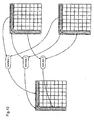
- the image coding apparatus employs the procedure shown in figure 12 instead of the procedure of generating prediction values of DCT coefficients of the target block by frame prediction in step S52 shown in figure 5, and employs the procedure shown in figure 13 instead of the procedure of generating prediction values of DCT coefficients of the target block by field prediction in step S53 shown in figure 5.
- the adaptive intra-frame DCT coefficient prediction by the image coding apparatus according to this third embodiment is fundamentally identical to that according to the first embodiment except the frame prediction method and the field prediction method and, therefore, only these prediction methods will be described hereinafter using figures 12 and 13.
- Figure 12 is a flowchart showing the procedure according to this third embodiment for implementing the frame prediction method in step S52 shown in figure 5.
- r0(i), r1(i), r2(i), and x(i) denote the reference blocks and the target block shown in figure 4(a).
- step S1221a the DCT type of the reference block r2(i) is decided.
- the subsequent process depends on the result of this decision.
- prediction values of DCT coefficients of the target block x(i) are generated using the DCT coefficients of the reference block r1(i), in similar manner to the conventional method shown in figure 15 in which prediction values of DCT coefficients of the target block X are generated from the DCT coefficients of the reference block R1.
- Figure 13 is a flowchart showing the procedure according to this third embodiment for implementing the field prediction method in step S53 shown in figure 5. Since the process shown in figure 13 is fundamentally identical to the process shown in figure 12 except that "frame” is replaced with “field”, detailed description therefor is omitted. However, in figure 13, r0(i), r1(i), r2(i), and x(i) respectively denote the reference blocks and the tercet block shown in figure 4(b).
- the frame prediction method in step S52 in figure 5 and the field prediction method in step S53 are simplified as compared with the first embodiment, the intra-frame prediction in the DCT comein during the coding process is simplified, and the processing speed is increased.
- the image decoding apparatus employs the procedure shown in figure 12 instead of the procedure of generating prediction values of DCT coefficients of the target block by frame prediction in step S52 shown in figure 5, and employs the procedure shown in figure 13 instead of the procedure of generating prediction values of DCT coefficients of the target block by field prediction in step S53 shown in figure 5.
- the frame prediction method in step S52 in figure 5 and the field prediction method in step S53 are simplified as compared with the second embodiment. Therefore, the intra-frame prediction in the DCT domain during the decoding process is simplified, and the processing speed is increased.
- an image processing apparatus an image coding apparatus
- an image processing method an image coding method according to a fifth embodiment of the present invention
- intra-frame coding of an image signal is performed, by generating prediction values of DCT coefficients of the target block from DCT coefficients of a coded block which has a prescribed positional relationship with the coded block.
- the DCT type signal indicates whether the target block has been processed by the frame DCT or the field DCT.
- a block is one of 4 subblocks each comprising 8 x 8 pixels of a macroblock comprising 16 x 16 pixels. These 4 subblocks are positioned upper left (area (0) in figure 3), upper right (area (1) in figure 3), lower left (area (2) in figure 3), and lower right (area (3) in figure 3) in the macroblock, respectively.
- FIG 17 is a block diagram showing an image coding apparatus of the fifth embodiment. First, construction of the image coding apparatus will be described.
- the image coding apparatus 3000 is used to divide a digital image signal (input image signal) 110a into image signals corresponding to plural blocks into which an image space (frame) formed by the signal 110 is divided, and code the resulting image signals of respective blocks for each block.
- the image coding apparatus 3000 includes a blocking unit 100 for performing blocking to divide the image signal 110a into image signals corresponding to the respective blocks field by field or frame by frame as processing units of frequency transformation, and outputting the image signals of respective blocks 101 and a DCT type signal 102 indicating a processing unit of the frequency transformation.
- the blocking unit 100 is used for receiving the input image signal 110a, rearranging scanning lines for each macroblock for the field DCT, and outputting an image signal for each block comprising 8 x 8 pixels of the macroblock, when correlation of pixel values within field is higher than that in a frame.
- scanning lines are not rearranged and the input image signal 110a is output for each block from the blocking unit 100.
- the scanning lines are rearranged in such a manner that a first field image formed by image signals on odd-numbered horizontal pixel rows (horizontal scanning lines) is positioned at an upper side of the macroblock, i.e., the areas (0) and (1), and a second field image formed by image signals on even-numbered horizontal pixel rows (horizontal scanning lines) is positioned at a lower side of the macroblock, i.e., the areas (2) and (3).
- the blocking unit 100 is used for dividing the image signal of the macroblock into image signals corresponding to the areas (0)-(3), and outputting the resulting image signals of respective blocks.
- the image coding apparatus 3000 further includes a DCT unit 103 for performing DCT to the image signals 101 of the target block, a quantizer 105 for quantizing signals output front the DCT unit 103, an intra-frame prediction unit 310 for generating prediction values 111 of the target block, an adder 107 for subtracting the prediction values 111 from signals 106 (DCT coefficient quantization value) output from the quantizer 105, and outputting DCT coefficient difference values 108, and a VLC 109 for performing variable length coding to the difference values 108 and outputting a bit stream (a coded image signal) 110b.
- a DCT unit 103 for performing DCT to the image signals 101 of the target block
- a quantizer 105 for quantizing signals output front the DCT unit 103
- an intra-frame prediction unit 310 for generating prediction values 111 of the target block
- an adder 107 for subtracting the prediction values 111 from signals 106 (DCT coefficient quantization value) output from the quantizer 105, and outputting DCT coefficient difference
- the intra-frame prediction unit 310 comprises an adder 112 for adding the difference values 106 to the prediction values 111, a block memory 115 for storing DCT coefficient quantization values 116 of the coded block output from the adder 112, and a DCT coefficient predictor 313 for generating the prediction values 111 from DOT coefficient quantization values 114 of the coded block adjacent to the target block in an image space.
- the DCT coefficient predictor 312 is used for generating the prediction values 111 of the DCT coefficient quantization values of a target block x (i) by referring to a block r0 (i) positioned upper left, a block r1 (i) positioned above, and a block r2 (i) positioned left, with respect to and adjacently to the target block x as references blocks, irrespective of a DCT type of the target block.
- the DCT unit 103, the quantizer 105, the adders 107 and 112, the VLC 109, and the block memory 115 are identical to those of the first embodiment.
- the blocking unit 100 blocks the signal 110a into image signals corresponding to the respective blocks trame by frame or field by field, and outputs the image signals 101 and the DCT type signal 102.
- the blocking unit 100 rearranges scanning lines for each macroblock comprising 16 x 16 pixels for the field DCT, and outputs the image signals for each block comprising 8 x 8 pixels of the macroblock, when correlation of pixel values between fields is higher than that in a frame.
- a first field "image formed by image signals on odd-numbered pixel rows is positioned at an upper side of the macroblock, i.e., areas (0) and (1)
- a second field image formed by image signals en even-numbered pixel rows is positioned at a lower side of the macroblock, i.e., areas (2) and (3).
- the blocking unit 100 does not rearrange scanning lines and outputs the input image signal 110a for each block.
- the DCT unit 103 transforms the image signals 101 into the frequency components (DCT coefficients) 104 by DCT.
- the quantizer 105 quantizes the DCT coefficients 104, and outputs the quantization values 106.
- the quantisation values 10E are input to the adder 107, which obtains the difference between the quantization values 106 and the prediction values 111, and outputs the DCT coefficient difference values 108, which are variable length coded by the VLC 109, and output as the bit stream (the coded image signal) 110b.
- the difference values 108 are also input to the intra-frame prediction unit 310, which generates the prediction values of the quantization values 106 as follows.
- the adder 112 adds the difference values 108 to the prediction values 111, and the resulting DCT coefficient quantization values 116 of the coded block is stored in the block memory 115.
- the predictor 313 generates the prediction values 111 of the DCT coefficient quantization values of the target block from the DCT quantization values 114 output from the block memory 115.
- the intra-frame DCT coefficient prediction method of this embodiment differs from that of the first embodiment in that prediction values of the DCT coefficients of the target block are generated by referring to the coded block which has a prescribed positional relationship with the target block, irrespective of a DCT type of the target block.
- a DCT domain (frequency domain) is formed by frequency components in which an image signal forming the image space (spatial domain) has been processed by DCT and respective macroblocks are arranged in the DCT domain as in the case of the macroblocks in the spatial domain.
- the image signal of each block is processed by DCT without rearranging scanning lines of the macroblock, and DCT coefficients or blocks positioned upper left, upper right, lower left, and lower right in the macroblock in the spatial domain are arranged in the areas (0), (1), (2), and (3) of the macroblock in the DCT domain, respectively, while in the case of processing the macroblock by field DCT, after rearrangement of scanning lines of the macroblock, the image signal of each block is processed by DCT, and DCT coefficients of respective blocks of the first field left, the first field right, the second field left, and the second field right are arranged in the areas (0), (1), (2) and (3).
- the intra-frame DCT coefficient prediction method of the fifth embodiment will now be described in detail.
- a block positioned upper left, a block positioned above, a block positioned left, with respect to the target block x(i) are used as a reference block r0(i), a reference block r1(i), and a reference block r2(i), respectively.
- Step S2130a comparison is made between an absolute value
- Step S2132a DCT coefficients of the reference block r1(i) are used to generate prediction values of DCT coefficients of the target block x(i).
- Step S2131a DCT coefficients of the reference block r2(i) are used to generate prediction values of DCT coefficients of the target block x(i).
- the coded block which has a prescribed positional relationship with the target block is used as the reference block, and comparison is made between correlation of DCT coefficients between adjacent reference blocks arranged in the vertical direction and correlation of DCT coefficients between adjacent reference blocks arranged in the horizontal direction in the vicinity of the target block, to decide which of these has higher correlation, a reference block with higher correlation with respect to the target block is selected, and from CCT coefficients of the selected reference block, prediction values of DCT coefficients of the target block are generated. Therefore, infra-frame prediction of the interlaced image signal or the specific progressive image is carried out in the DCT domain with efficiency and following simple procedure.
- infra-frame information is used to improve efficiency in prediction of DCT coefficients of the target block, and thereby compressive coding of an image signal is realized while reducing spatially redundant image information.
- DCT coefficients of the reference block r2(i) in figure 19 are used as prediction values of DCT coefficients of the target block x(i), and DCT types of the reference block r2(i) and the target block x(i) differ from each other, only DCT component of the DCT coefficients of the reference block r2(i) may be used as prediction values of DCT coefficients of the target block x(i).
- an image processing apparatus an image decoding apparatus
- an image processing method an image decoding method according to a sixth embodiment
- a coded image signal is decoded by the use of the intra-frame DCT coefficient prediction method for use by the image coding apparatus and the image coding method of the fifth embodiment.
- Figure 18 is a block diagram showing an image decoding apparatus of the sixth embodiment, and in the figure, the same reference numerals as those in figure 7 designate the same or the corresponding parts. First, construction of the image decoding apparatus will be described.
- the image decoding apparatus 4000 is used to receive the coded image signal (bit stream) 110b which has been coded by the image coding apparatus 3000 of the fifth embodiment, and decode the coded image signal 110b by the use of the intra-frame DCT coefficient prediction method.
- the image decoding apparatus 4000 includes a variable length decoder (VLC) 203 for receiving the bit stream 110b, performing variable length decoding to the bit stream 110b by data analysis to restore the DCT coefficient difference values 108 (difference values between the DCT coefficient quantization values 107 and the prediction values 111) of a target block to-be-decoded (target block), an intra-frame prediction unit 410 for generating intra-frame prediction values 111 of the target block, and an adder 112 for adding the prediction values 111 to the difference values 108 to restore DCT coefficient quantization values 116 cf the target block.
- VLC variable length decoder
- the intra-frame prediction unit 410 includes a block memory 115 for storing the signals 116 output from the adder 112 as DCT coefficient quantization values of a decoded block (a block which has been already decoded), and a DCT coefficient predictor 313 for generating prediction values 111 of the DCT coefficient quantization values of the target block from the DCT coefficient quantization values 114 stored in the block memory 115.
- the image decoding apparatus 4000 further includes an inverse quantizer 207 for inversely quantizing the signals 116 output from the adder 112 to restore DCT coefficients 104 of the target block, an inverse DCT unit 209 for performing inverse DCT to the DCT coefficients 104 output from the inverse quantizer 207 to restore an image signal 101 of the target block and an inverse blocking unit 200 for receiving the signals 101 output from the inverse DCT unit 209 and restoring an image signal 110a of a scanning line structure on the basis of the DCT type signal 102 output from the image coding apparatus 4000.
- an inverse quantizer 207 for inversely quantizing the signals 116 output from the adder 112 to restore DCT coefficients 104 of the target block
- an inverse DCT unit 209 for performing inverse DCT to the DCT coefficients 104 output from the inverse quantizer 207 to restore an image signal 101 of the target block
- an inverse blocking unit 200 for receiving the signals 101 output from the inverse DCT unit 209 and restoring an image signal
- the inverse blocking unit 200 functions as follows.
- the inverse blocking unit 200 combines image signals of blocks which belong to the same macroblock in an image space correspondingly to block positions in the macroblock, to generate an image signal of the macroblock, and with respect to the image signal of the macroblock in which horizontal pixel rows have been rearranged in its coding process so that the first field image formed by image signals on odd-numbered pixel rows is positioned at an upper side of the macroblock, and the second field image formed by image signals on even-numbered horizontal pixel rows is positioned at a lower side of the macroblock, it performs rearrangement for restoration to the horizontal pixel rows so as to form a frame image comprising the first and second fields, while with respect to the image signal of the macroblock in which horizontal pixel rows have not been rearranged, it generates an image signal forming an image space comprising plural macroblocks without performing rearrangement for restoration to the horizontal pixel values.
- the signal 110b is variable length decoded by data analysis by the VLD 203, and the DCT coefficient difference values 108 of the target block are output therefrom.
- the difference values 108 are added to the prediction values 111 by the adder 112 to restore the DCT coefficient quantization values 116 of the target block.
- the DCT coefficient quantization values 116 are input to the intra-frame prediction unit 410, where the values 116 are stored as the DCT coefficient quantization values of the decoded block in the block memory 11b, and then the DCT coefficient quantization values 114 of the decoded block are read from the block memory 115 to the DCT coefficient predictor 313, in which prediction values of the DCT coefficient difference value 108 of a subsequent target block (a block to-be-processed subsequent to the target block are generated by referring to the DCT coefficient quantisation values 114 output from the block memory 115, as in the case of the intra-frame prediction unit 110 of the image coding apparatus 3000.
- the DCT coefficient quantization values 116 are input to the inverse quantizer 207, where they are converted into the DCT coefficients 104 of the target block by inverse quantization, and then the DCT coefficients 104 are transformed into the image signal 101 of the target block by inverse DCT by the inverse DCT unit 209.
- the image signals 101 are input to the inverse blocking unit 200, which reproduces the image signal 110a of a scanning line structure on the basis of the DCT type signal 102 transmitted from the image coding apparatus 1000.
- the coded image signal is decoded by the use of the intra-frame DCT coefficient prediction method. Therefore, it is possible to efficiently and correctly decode the coded image signal (bit stream) in which the image signal of the interlaced, image signal or the specific progressive image has been intra-frame coded by the intra-frame DCT coefficient prediction, by simple intra-frame prediction in the DCT domain.
- a coding or cecoding program which implements construction of image processing of the shape coding apparatus or shape decoding apparatus of each embodiment is recorded in a data recording medium such as a floppy disc, whereby the processing cf each embodiment is carried out in an independent computer with ease. This is described below.
- Figures 14 (a)-14 (c) are diagrams showing a case in which the coding or decoding in each of the first to sixth embodiments is carried out in a computer system using a floppy disc in which the coding or decoding program is stored.
- Figure 14(a) shows a front appearance and a cross-section of a floppy disc FD, and a floppy disc body D.
- Figure 14(b) shows a physical, format of the floppy disc body D.
- the floppy disc body D is stored in a floppy disc case F and in a surface thereof, plural tracks Trs are formed concentrically from outer to inner radius thereof, each track being divided into 16 sectors Se in an angle direction. Data of the program is recorded in allocated regions on the floppy disc body 0.
- Figure 14(c) is a diagram showing a construction with which the program is recorded/regenerated in/from the floppy disc FD.
- data of the program is written thereto through a floppy disc drive FDD from a computer system Cs.
- the program is read from the floppy disc FD by means of the floppy disc drive FDD and transferred to the computer system Cs.
- the floppy disc is used as the data recording medium herain, an optical disc may be used.
- the data recording medium is not limited to these, and an IC card, an ROM cassette, or the like may be used to implement the coding or decoding so long as it can record a program.
Landscapes
- Engineering & Computer Science (AREA)
- Multimedia (AREA)
- Signal Processing (AREA)
- Compression Or Coding Systems Of Tv Signals (AREA)
- Compression Of Band Width Or Redundancy In Fax (AREA)
- Color Television Systems (AREA)
Claims (3)
- Procédé de traitement d'image destiné à décoder un signal d'image codé pour chaque sous-bloc, ledit signal d'image codé étant obtenu en codant un signal d'image qui forme un espace d'image comprenant plusieurs pixels, par l'un d'un procédé de codage comprenant le réagencement de lignes de pixels horizontales et une conversion de fréquence, et d'un procédé de codage excluant le réagencement de lignes de pixels horizontales et comprenant une conversion de fréquence, pour chacun des sous-blocs qui sont des composants de macroblocs rectangulaires individuels en lesquels l'espace d'image est divisé, ledit procédé comprenant :une étape de prédiction consistant à générer une valeur de prédiction d'une composante de fréquence d'un sous-bloc cible à décoder, en faisant référence à une composante de fréquence de l'un des sous-blocs qui ont déjà été décodés et sont positionnés à proximité et au-dessus du sous-bloc cible, et à proximité et à la gauche du sous-bloc cible,une étape de restauration consistant à restaurer les composantes de fréquences du sous-bloc cible en utilisant la valeur de prédiction à partir du signal d'image codé correspondant au sous-bloc cible,une étape de transformation consistant à transformer les composantes de fréquences restaurées du sous-bloc cible en un signal d'image du sous-bloc cible par transformation de fréquence inverse, etune étape de génération de signal consistant à combiner les signaux d'image de sous-blocs qui appartiennent au même macrobloc dans l'espace d'image en faisant référence à des positions de sous-blocs dans le macrobloc, afin de générer ainsi un signal d'image correspondant au macrobloc,ledit procédé étant caractérisé en ce que,dans ladite étape de transformation, une transformation de fréquence inverse en unités de champ est exécutée pour un macrobloc dans lequel les lignes de pixels horizontales ont été réagencées au cours du codage de sorte qu'un signal d'image d'un premier champ de l'espace d'image est positionné au niveau du côté supérieur du macrobloc, et un signal d'image d'un second champ de l'espace d'image est positionné au niveau du côté inférieur du macrobloc, alors qu'une transformation de fréquence inverse en unités de trames est exécutée pour un macrobloc dans lequel les lignes de pixels horizontales n'ont pas été réagencées au cours du codage,dans ladite étape de génération de signal, le réagencement inverse de lignes de pixels horizontales est exécuté pour le macrobloc dans lequel les lignes de pixels horizontales ont été réagencées au cours du codage de manière à former un signal d'image d'une trame comprenant le premier champ et le second champ, alors qu'un réagencement inverse de lignes de pixels horizontales n'est pas exécuté pour le macrobloc dans lequel les lignes de pixels horizontales n'ont pas été réagencées au cours du codage, et un signal d'image correspondant à ce macrobloc est reproduit, etdans ladite étape de prédiction, indépendamment du fait que les sous-blocs décodés ont été soumis ou non à un agencement de lignes de pixels horizontales au cours du codage, il est décidé à laquelle de la composante de fréquence du sous-bloc décodé positionné à proximité du et au-dessus du sous-bloc cible, et de la composante de fréquence du sous-bloc décodé positionné à proximité du et à la gauche du bloc cible il devrait être fait référence, sur la base des composantes de fréquence continue des sous-blocs décodés qui sont positionnés à proximité du et au-dessus du bloc cible, à proximité du et à la gauche du bloc cible, et à proximité du et à la partie supérieure gauche du bloc cible, et en outre, un sous-bloc décodé inclus dans le macrobloc cible comprenant le sous-bloc cible ou un sous-bloc décodé inclus dans un macrobloc décodé qui est positionné au-dessus du macrobloc cible comprenant le sous-bloc cible est utilisé en tant que sous-bloc décodé auquel il doit être fait référence, lequel est positionné à proximité du et au-dessus du sous-bloc cible, selon la position du sous-bloc cible dans le macrobloc cible.
- Procédé de traitement d'image selon la revendication 1, dans lequel, dans ladite étape de prédiction,
en tant que sous-bloc décodé positionné à proximité du et au-dessus du sous-bloc cible, un sous-bloc décodé du côté supérieur qui est positionné au-dessus et de manière adjacente au sous-bloc cible est utilisé,
en tant que sous-bloc décodé positionné à proximité du et à la gauche du sous-bloc cible, un sous-bloc décodé du côté gauche qui est positionné à la gauche et de manière adjacente au sous-bloc cible est utilisé,
en tant que sous-bloc décodé positionné à proximité du et dans la partie supérieure gauche du sous-bloc cible, un sous-bloc décodé du côté supérieur gauche qui est positionné au niveau de la partie supérieure gauche du bloc cible et de manière adjacente à celui-ci, est utilisé,
lorsque la valeur absolue d'une différence entre la composante de fréquence continue du sous-bloc décodé du côté supérieur et la composante de fréquence continue du sous-bloc décodé du côté supérieur gauche est plus petite que la valeur absolue d'une différence entre la composante de fréquence continue du sous-bloc décodé du côté gauche et la composante de fréquence continue du sous-bloc décodé du côté supérieur gauche, une valeur de prédiction de la composante de fréquence du sous-bloc cible est générée en faisant référence à la composante de fréquence du sous-bloc décodé du côté gauche, et
en revanche, lorsque la valeur absolue de la différence entre la composante de fréquence continue du sous-bloc décodé du côté gauche et la composante de fréquence continue du sous-bloc décodé du côté supérieur gauche est plus petite que la valeur absolue de la différence entre la composante de fréquence continue du sous-bloc décodé du côté supérieur et la composante de fréquence continue du sous-bloc décodé du côté supérieur gauche, une valeur de prédiction de la composante de fréquence du sous-bloc cible est générée en faisant référence à la composante de fréquence du sous-bloc décodé du côté supérieur. - Procédé de traitement d'image selon la revendication 1 ou 2, dans laquelle dans ladite étape de prédiction, une valeur de prédiction de la composante de fréquence du sous-bloc cible est générée sur la base de la composante de fréquence quantifiée, et, dans ladite étape de transformation, la transformation de fréquence inverse est exécutée pour la composante de fréquence quantifiée inverse.
Applications Claiming Priority (3)
| Application Number | Priority Date | Filing Date | Title |
|---|---|---|---|
| JP16465497 | 1997-06-20 | ||
| JP16465497 | 1997-06-20 | ||
| EP98111302A EP0888013A3 (fr) | 1997-06-20 | 1998-06-19 | Méthode de traitement d'images, dispositif de traitement d'images, et support d'enregistrement de données |
Related Parent Applications (1)
| Application Number | Title | Priority Date | Filing Date |
|---|---|---|---|
| EP98111302A Division EP0888013A3 (fr) | 1997-06-20 | 1998-06-19 | Méthode de traitement d'images, dispositif de traitement d'images, et support d'enregistrement de données |
Publications (3)
| Publication Number | Publication Date |
|---|---|
| EP1124380A2 EP1124380A2 (fr) | 2001-08-16 |
| EP1124380A3 EP1124380A3 (fr) | 2004-05-12 |
| EP1124380B1 true EP1124380B1 (fr) | 2006-04-12 |
Family
ID=15797292
Family Applications (2)
| Application Number | Title | Priority Date | Filing Date |
|---|---|---|---|
| EP01104611A Expired - Lifetime EP1124380B1 (fr) | 1997-06-20 | 1998-06-19 | Méthode de traitement d'images |
| EP98111302A Withdrawn EP0888013A3 (fr) | 1997-06-20 | 1998-06-19 | Méthode de traitement d'images, dispositif de traitement d'images, et support d'enregistrement de données |
Family Applications After (1)
| Application Number | Title | Priority Date | Filing Date |
|---|---|---|---|
| EP98111302A Withdrawn EP0888013A3 (fr) | 1997-06-20 | 1998-06-19 | Méthode de traitement d'images, dispositif de traitement d'images, et support d'enregistrement de données |
Country Status (8)
| Country | Link |
|---|---|
| US (1) | US6275533B1 (fr) |
| EP (2) | EP1124380B1 (fr) |
| KR (1) | KR100303373B1 (fr) |
| CN (1) | CN1202650C (fr) |
| DE (1) | DE69834209T2 (fr) |
| ES (1) | ES2259631T3 (fr) |
| MY (1) | MY119926A (fr) |
| TW (1) | TW398131B (fr) |
Cited By (1)
| Publication number | Priority date | Publication date | Assignee | Title |
|---|---|---|---|---|
| RU2369037C2 (ru) * | 2005-04-13 | 2009-09-27 | Нтт Докомо, Инк. | Устройство кодирования динамического изображения, устройство декодирования динамического изображения, способ кодирования динамического изображения, способ декодирования динамического изображения, программа кодирования динамического изображения и программа декодирования динамического изображения |
Families Citing this family (40)
| Publication number | Priority date | Publication date | Assignee | Title |
|---|---|---|---|---|
| US5974184A (en) * | 1997-03-07 | 1999-10-26 | General Instrument Corporation | Intra-macroblock DC and AC coefficient prediction for interlaced digital video |
| US6426975B1 (en) * | 1997-07-25 | 2002-07-30 | Matsushita Electric Industrial Co., Ltd. | Image processing method, image processing apparatus and data recording medium |
| FI117534B (fi) * | 2000-01-21 | 2006-11-15 | Nokia Corp | Menetelmä digitaalisten kuvien suodattamiseksi ja suodatin |
| US6970510B1 (en) | 2000-04-25 | 2005-11-29 | Wee Susie J | Method for downstream editing of compressed video |
| US6553150B1 (en) | 2000-04-25 | 2003-04-22 | Hewlett-Packard Development Co., Lp | Image sequence compression featuring independently coded regions |
| US6973130B1 (en) | 2000-04-25 | 2005-12-06 | Wee Susie J | Compressed video signal including information for independently coded regions |
| US6507618B1 (en) * | 2000-04-25 | 2003-01-14 | Hewlett-Packard Company | Compressed video signal including independently coded regions |
| US20020191695A1 (en) * | 2001-06-07 | 2002-12-19 | Irvine Ann Chris | Interframe encoding method and apparatus |
| US7266150B2 (en) | 2001-07-11 | 2007-09-04 | Dolby Laboratories, Inc. | Interpolation of video compression frames |
| US6921593B2 (en) * | 2001-09-28 | 2005-07-26 | Hewlett-Packard Development Company, L.P. | Fuel additives for fuel cell |
| EP1322121A3 (fr) * | 2001-12-19 | 2003-07-16 | Matsushita Electric Industrial Co., Ltd. | Codeur/Décodeur vidéo à estimation de mouvement améliorée |
| KR100454501B1 (ko) * | 2001-12-26 | 2004-10-28 | 브이케이 주식회사 | 영상신호를 부호화 또는 복호화하기 위한 예측 장치 및 방법 |
| KR101017094B1 (ko) * | 2002-06-11 | 2011-02-25 | 노키아 코포레이션 | 인트라 코딩에 기반한 공간 예측 |
| JP3975188B2 (ja) | 2002-09-30 | 2007-09-12 | 三星電子株式会社 | 色相の空間予測符号化を利用した映像の符号化及び復号化方法及び装置 |
| CA2763080C (fr) * | 2002-10-01 | 2014-12-02 | Panasonic Corporation | Dispositif de codage d'image, dispositif de decodage d'image et techniques associees |
| KR100967237B1 (ko) | 2002-11-01 | 2010-06-30 | 파나소닉 주식회사 | 동화상 부호화 방법 및 동화상 복호화 방법 |
| SE527621C2 (sv) | 2003-06-10 | 2006-04-25 | Jan-Olov Stroemberg | Metod och system för komprimering av bilddata |
| US7286710B2 (en) * | 2003-10-01 | 2007-10-23 | Fraunhofer-Gesellschaft Zur Foerderung Der Angewandten Forschung E.V. | Coding of a syntax element contained in a pre-coded video signal |
| US7379608B2 (en) * | 2003-12-04 | 2008-05-27 | Fraunhofer-Gesellschaft Zur Foerderung Der Angewandten Forschung, E.V. | Arithmetic coding for transforming video and picture data units |
| US7599435B2 (en) | 2004-01-30 | 2009-10-06 | Fraunhofer-Gesellschaft Zur Foerderung Der Angewandten Forschung E.V. | Video frame encoding and decoding |
| US7586924B2 (en) * | 2004-02-27 | 2009-09-08 | Fraunhofer-Gesellschaft Zur Foerderung Der Angewandten Forschung E.V. | Apparatus and method for coding an information signal into a data stream, converting the data stream and decoding the data stream |
| US7304646B2 (en) * | 2004-08-19 | 2007-12-04 | Sony Computer Entertainment Inc. | Image data structure for direct memory access |
| CN101686397B (zh) * | 2004-09-16 | 2013-07-31 | 汤姆逊许可证公司 | 用于快速视频帧和场编码的方法 |
| KR100727972B1 (ko) * | 2005-09-06 | 2007-06-14 | 삼성전자주식회사 | 영상의 인트라 예측 부호화, 복호화 방법 및 장치 |
| CN100425078C (zh) * | 2005-11-08 | 2008-10-08 | 上海广电(集团)有限公司中央研究院 | 码流转换中编码速度和视频质量的自适应联合控制方法 |
| JP2007312810A (ja) * | 2006-05-23 | 2007-12-06 | Olympus Corp | 画像処理装置 |
| EP2096439A4 (fr) * | 2006-12-21 | 2011-01-05 | Ajinomoto Kk | Procede, appareil, procede, systeme et logiciel d'evaluation du cancer colorectal, et support d'enregistrement |
| JP4707118B2 (ja) * | 2007-03-28 | 2011-06-22 | 株式会社Kddi研究所 | 動画像符号化装置および動画像復号装置のイントラ予測方式 |
| JP2009094828A (ja) | 2007-10-10 | 2009-04-30 | Hitachi Ltd | 画像符号化装置及び画像符号化方法、画像復号化装置及び画像復号化方法 |
| KR101456279B1 (ko) | 2008-01-03 | 2014-11-04 | 한국전자통신연구원 | 참조 블록 파형 정보에 기반하여 인트라 영상을 부호화하는 장치 및 복호화 하는 장치 |
| US8848779B2 (en) * | 2010-07-15 | 2014-09-30 | Sharp Laboratories Of America, Inc. | Method of parallel video coding based on block size |
| CN102685484B (zh) * | 2011-03-11 | 2014-10-08 | 华为技术有限公司 | 编码方法以及装置、解码方法以及装置 |
| CN102685483B (zh) * | 2011-03-11 | 2014-12-03 | 华为技术有限公司 | 解码方法 |
| CN102685478B (zh) * | 2011-03-11 | 2015-04-29 | 华为技术有限公司 | 编码方法以及装置、解码方法以及装置 |
| EP2721816A4 (fr) * | 2011-06-16 | 2015-03-18 | Freescale Semiconductor Inc | Procédé et dispositif de codage et de décodage d'une image |
| TWI523497B (zh) * | 2011-11-10 | 2016-02-21 | Sony Corp | Image processing apparatus and method |
| CN103248889B (zh) * | 2013-03-22 | 2016-05-25 | 海信集团有限公司 | 一种图像处理方法及装置 |
| WO2016123398A2 (fr) | 2015-01-29 | 2016-08-04 | Vid Scale, Inc. | Recherche de copie intra-bloc |
| CN114173117B (zh) * | 2016-12-27 | 2023-10-20 | 松下电器(美国)知识产权公司 | 编码方法、解码方法及发送方法 |
| KR102772028B1 (ko) | 2017-09-15 | 2025-02-26 | 소니그룹주식회사 | 화상 처리 장치 및 방법 |
Family Cites Families (8)
| Publication number | Priority date | Publication date | Assignee | Title |
|---|---|---|---|---|
| JPH01205667A (ja) | 1988-02-12 | 1989-08-18 | Nec Corp | 動画像信号符号装置 |
| TW199257B (fr) | 1991-07-30 | 1993-02-01 | Sony Co Ltd | |
| US5539466A (en) * | 1991-07-30 | 1996-07-23 | Sony Corporation | Efficient coding apparatus for picture signal and decoding apparatus therefor |
| FI90179C (fi) * | 1991-09-23 | 1993-12-27 | Nokia Oy Ab | Foerfarande foer kompressering av en videobild, som kodats digitaliskt |
| US5227878A (en) * | 1991-11-15 | 1993-07-13 | At&T Bell Laboratories | Adaptive coding and decoding of frames and fields of video |
| US5666461A (en) * | 1992-06-29 | 1997-09-09 | Sony Corporation | High efficiency encoding and decoding of picture signals and recording medium containing same |
| KR0166722B1 (ko) | 1992-11-30 | 1999-03-20 | 윤종용 | 부호화 및 복호화방법 및 그 장치 |
| JP3552811B2 (ja) * | 1995-09-29 | 2004-08-11 | 三菱電機株式会社 | ディジタル映像信号符号化装置および復号化装置 |
-
1998
- 1998-06-18 US US09/099,750 patent/US6275533B1/en not_active Expired - Lifetime
- 1998-06-18 TW TW087109755A patent/TW398131B/zh not_active IP Right Cessation
- 1998-06-19 CN CNB981172202A patent/CN1202650C/zh not_active Expired - Lifetime
- 1998-06-19 DE DE69834209T patent/DE69834209T2/de not_active Expired - Lifetime
- 1998-06-19 EP EP01104611A patent/EP1124380B1/fr not_active Expired - Lifetime
- 1998-06-19 ES ES01104611T patent/ES2259631T3/es not_active Expired - Lifetime
- 1998-06-19 EP EP98111302A patent/EP0888013A3/fr not_active Withdrawn
- 1998-06-20 KR KR1019980023256A patent/KR100303373B1/ko not_active Expired - Lifetime
- 1998-06-20 MY MYPI98002794A patent/MY119926A/en unknown
Cited By (2)
| Publication number | Priority date | Publication date | Assignee | Title |
|---|---|---|---|---|
| RU2369037C2 (ru) * | 2005-04-13 | 2009-09-27 | Нтт Докомо, Инк. | Устройство кодирования динамического изображения, устройство декодирования динамического изображения, способ кодирования динамического изображения, способ декодирования динамического изображения, программа кодирования динамического изображения и программа декодирования динамического изображения |
| US8340175B2 (en) | 2005-04-13 | 2012-12-25 | Ntt Docomo, Inc. | Dynamic image encoding device, dynamic image decoding device, dynamic image encoding method, dynamic image decoding method, dynamic image encoding program, and dynamic image decoding program |
Also Published As
| Publication number | Publication date |
|---|---|
| KR100303373B1 (ko) | 2001-09-24 |
| EP0888013A2 (fr) | 1998-12-30 |
| ES2259631T3 (es) | 2006-10-16 |
| TW398131B (en) | 2000-07-11 |
| DE69834209T2 (de) | 2006-11-09 |
| KR19990007178A (ko) | 1999-01-25 |
| DE69834209D1 (de) | 2006-05-24 |
| US6275533B1 (en) | 2001-08-14 |
| EP1124380A2 (fr) | 2001-08-16 |
| MY119926A (en) | 2005-08-30 |
| CN1202650C (zh) | 2005-05-18 |
| CN1212561A (zh) | 1999-03-31 |
| EP1124380A3 (fr) | 2004-05-12 |
| EP0888013A3 (fr) | 1999-02-10 |
Similar Documents
| Publication | Publication Date | Title |
|---|---|---|
| US6275533B1 (en) | Image processing method, image processing apparatus, and data recording medium | |
| US6426975B1 (en) | Image processing method, image processing apparatus and data recording medium | |
| EP2268040B1 (fr) | Codage trame/champ à niveau adaptatif de macrobloc pour un contenu vidéo numérique | |
| EP1449385B1 (fr) | Codage trame/champ a niveau adaptatif de macrobloc pour un contenu video numerique | |
| CA2228166C (fr) | Procede et dispositif d'anticipation et de codage d'image, procede et dispositif d'anticipation et de decodage d'image, et support d'enregistrement | |
| US6359929B1 (en) | Image predictive decoding method, image predictive decoding apparatus, image predictive coding apparatus, and data storage medium | |
| JP3686436B2 (ja) | 映像信号の復号化方法 | |
| US8300689B2 (en) | Apparatus and method for encoding and decoding image containing gray alpha channel image | |
| EP3373580B1 (fr) | Codage d'intra-prédiction utilisant des représentations planes | |
| US20040042673A1 (en) | Digital image coding/decoding method and data recording medium | |
| US20080084932A1 (en) | Controlling loop filtering for interlaced video frames | |
| US20060093041A1 (en) | Intra-frame prediction for high-pass temporal-filtered frames in wavelet video coding | |
| JP3671286B2 (ja) | 画像処理方法,画像処理装置,及びデータ記憶媒体 | |
| JP4213526B2 (ja) | 画像処理方法 | |
| JPH06244736A (ja) | 符号化装置 |
Legal Events
| Date | Code | Title | Description |
|---|---|---|---|
| PUAI | Public reference made under article 153(3) epc to a published international application that has entered the european phase |
Free format text: ORIGINAL CODE: 0009012 |
|
| AC | Divisional application: reference to earlier application |
Ref document number: 888013 Country of ref document: EP |
|
| AK | Designated contracting states |
Kind code of ref document: A2 Designated state(s): DE ES FR GB IT |
|
| RIN1 | Information on inventor provided before grant (corrected) |
Inventor name: NISHI, TAKAHIRO |
|
| PUAL | Search report despatched |
Free format text: ORIGINAL CODE: 0009013 |
|
| AK | Designated contracting states |
Kind code of ref document: A3 Designated state(s): DE ES FR GB IT |
|
| RIC1 | Information provided on ipc code assigned before grant |
Ipc: 7H 04N 7/34 B Ipc: 7H 04N 7/30 A |
|
| 17P | Request for examination filed |
Effective date: 20041112 |
|
| AKX | Designation fees paid |
Designated state(s): DE ES FR GB IT |
|
| 17Q | First examination report despatched |
Effective date: 20041229 |
|
| GRAP | Despatch of communication of intention to grant a patent |
Free format text: ORIGINAL CODE: EPIDOSNIGR1 |
|
| RTI1 | Title (correction) |
Free format text: IMAGE PROCESSING METHOD |
|
| GRAS | Grant fee paid |
Free format text: ORIGINAL CODE: EPIDOSNIGR3 |
|
| GRAA | (expected) grant |
Free format text: ORIGINAL CODE: 0009210 |
|
| AC | Divisional application: reference to earlier application |
Ref document number: 0888013 Country of ref document: EP Kind code of ref document: P |
|
| AK | Designated contracting states |
Kind code of ref document: B1 Designated state(s): DE ES FR GB IT |
|
| REG | Reference to a national code |
Ref country code: GB Ref legal event code: FG4D |
|
| REF | Corresponds to: |
Ref document number: 69834209 Country of ref document: DE Date of ref document: 20060524 Kind code of ref document: P |
|
| REG | Reference to a national code |
Ref country code: ES Ref legal event code: FG2A Ref document number: 2259631 Country of ref document: ES Kind code of ref document: T3 |
|
| ET | Fr: translation filed | ||
| PLBE | No opposition filed within time limit |
Free format text: ORIGINAL CODE: 0009261 |
|
| STAA | Information on the status of an ep patent application or granted ep patent |
Free format text: STATUS: NO OPPOSITION FILED WITHIN TIME LIMIT |
|
| 26N | No opposition filed |
Effective date: 20070115 |
|
| REG | Reference to a national code |
Ref country code: GB Ref legal event code: 732E Free format text: REGISTERED BETWEEN 20140612 AND 20140618 |
|
| REG | Reference to a national code |
Ref country code: DE Ref legal event code: R082 Ref document number: 69834209 Country of ref document: DE Representative=s name: EISENFUEHR SPEISER PATENTANWAELTE RECHTSANWAEL, DE |
|
| REG | Reference to a national code |
Ref country code: DE Ref legal event code: R081 Ref document number: 69834209 Country of ref document: DE Owner name: PANASONIC INTELLECTUAL PROPERTY CORPORATION OF, US Free format text: FORMER OWNER: PANASONIC CORPORATION, KADOMA-SHI, OSAKA, JP Effective date: 20140711 Ref country code: DE Ref legal event code: R082 Ref document number: 69834209 Country of ref document: DE Representative=s name: EISENFUEHR SPEISER PATENTANWAELTE RECHTSANWAEL, DE Effective date: 20140711 Ref country code: DE Ref legal event code: R081 Ref document number: 69834209 Country of ref document: DE Owner name: SUN PATENT TRUST, NEW YORK, US Free format text: FORMER OWNER: PANASONIC CORPORATION, KADOMA-SHI, OSAKA, JP Effective date: 20140711 |
|
| REG | Reference to a national code |
Ref country code: FR Ref legal event code: TP Owner name: PANASONIC INTELLECTUAL PROPERTY CORPORATION OF, US Effective date: 20140722 |
|
| REG | Reference to a national code |
Ref country code: ES Ref legal event code: PC2A Owner name: PANASONIC CORPORATION Effective date: 20150413 |
|
| REG | Reference to a national code |
Ref country code: ES Ref legal event code: PC2A Owner name: PANASONIC INTELLECTUAL PROPERTY CORPORATION OF AME Effective date: 20150520 |
|
| REG | Reference to a national code |
Ref country code: FR Ref legal event code: PLFP Year of fee payment: 19 |
|
| REG | Reference to a national code |
Ref country code: DE Ref legal event code: R082 Ref document number: 69834209 Country of ref document: DE Representative=s name: EISENFUEHR SPEISER PATENTANWAELTE RECHTSANWAEL, DE Ref country code: DE Ref legal event code: R081 Ref document number: 69834209 Country of ref document: DE Owner name: SUN PATENT TRUST, NEW YORK, US Free format text: FORMER OWNER: PANASONIC INTELLECTUAL PROPERTY CORPORATION OF AMERICA, TORRANCE, CALIF., US |
|
| REG | Reference to a national code |
Ref country code: GB Ref legal event code: 732E Free format text: REGISTERED BETWEEN 20161229 AND 20170104 |
|
| REG | Reference to a national code |
Ref country code: FR Ref legal event code: PLFP Year of fee payment: 20 |
|
| REG | Reference to a national code |
Ref country code: FR Ref legal event code: RM Effective date: 20170518 |
|
| PGFP | Annual fee paid to national office [announced via postgrant information from national office to epo] |
Ref country code: GB Payment date: 20170614 Year of fee payment: 20 Ref country code: DE Payment date: 20170613 Year of fee payment: 20 Ref country code: FR Payment date: 20170511 Year of fee payment: 20 |
|
| PGFP | Annual fee paid to national office [announced via postgrant information from national office to epo] |
Ref country code: IT Payment date: 20170619 Year of fee payment: 20 |
|
| REG | Reference to a national code |
Ref country code: ES Ref legal event code: PC2A Owner name: SUN PATENT TRUST Effective date: 20171009 |
|
| PGFP | Annual fee paid to national office [announced via postgrant information from national office to epo] |
Ref country code: ES Payment date: 20170706 Year of fee payment: 20 |
|
| REG | Reference to a national code |
Ref country code: DE Ref legal event code: R071 Ref document number: 69834209 Country of ref document: DE |
|
| REG | Reference to a national code |
Ref country code: GB Ref legal event code: PE20 Expiry date: 20180618 |
|
| PG25 | Lapsed in a contracting state [announced via postgrant information from national office to epo] |
Ref country code: GB Free format text: LAPSE BECAUSE OF EXPIRATION OF PROTECTION Effective date: 20180618 |
|
| REG | Reference to a national code |
Ref country code: ES Ref legal event code: FD2A Effective date: 20200721 |
|
| PG25 | Lapsed in a contracting state [announced via postgrant information from national office to epo] |
Ref country code: ES Free format text: LAPSE BECAUSE OF EXPIRATION OF PROTECTION Effective date: 20180620 |