EP1125547A2 - Anordnung zur Messung von Biosignalen - Google Patents
Anordnung zur Messung von Biosignalen Download PDFInfo
- Publication number
- EP1125547A2 EP1125547A2 EP01000011A EP01000011A EP1125547A2 EP 1125547 A2 EP1125547 A2 EP 1125547A2 EP 01000011 A EP01000011 A EP 01000011A EP 01000011 A EP01000011 A EP 01000011A EP 1125547 A2 EP1125547 A2 EP 1125547A2
- Authority
- EP
- European Patent Office
- Prior art keywords
- arrangement
- casing
- fastener
- measuring
- measurement target
- Prior art date
- Legal status (The legal status is an assumption and is not a legal conclusion. Google has not performed a legal analysis and makes no representation as to the accuracy of the status listed.)
- Granted
Links
Images


Classifications
-
- A—HUMAN NECESSITIES
- A61—MEDICAL OR VETERINARY SCIENCE; HYGIENE
- A61B—DIAGNOSIS; SURGERY; IDENTIFICATION
- A61B5/00—Measuring for diagnostic purposes; Identification of persons
- A61B5/68—Arrangements of detecting, measuring or recording means, e.g. sensors, in relation to patient
- A61B5/6801—Arrangements of detecting, measuring or recording means, e.g. sensors, in relation to patient specially adapted to be attached to or worn on the body surface
- A61B5/6802—Sensor mounted on worn items
- A61B5/681—Wristwatch-type devices
-
- A—HUMAN NECESSITIES
- A61—MEDICAL OR VETERINARY SCIENCE; HYGIENE
- A61B—DIAGNOSIS; SURGERY; IDENTIFICATION
- A61B5/00—Measuring for diagnostic purposes; Identification of persons
- A61B5/02—Detecting, measuring or recording for evaluating the cardiovascular system, e.g. pulse, heart rate, blood pressure or blood flow
- A61B5/024—Measuring pulse rate or heart rate
- A61B5/02438—Measuring pulse rate or heart rate with portable devices, e.g. worn by the patient
-
- A—HUMAN NECESSITIES
- A61—MEDICAL OR VETERINARY SCIENCE; HYGIENE
- A61B—DIAGNOSIS; SURGERY; IDENTIFICATION
- A61B5/00—Measuring for diagnostic purposes; Identification of persons
- A61B5/68—Arrangements of detecting, measuring or recording means, e.g. sensors, in relation to patient
- A61B5/6801—Arrangements of detecting, measuring or recording means, e.g. sensors, in relation to patient specially adapted to be attached to or worn on the body surface
- A61B5/6843—Monitoring or controlling sensor contact pressure
Definitions
- the invention relates to an arrangement for measuring a biosignal from a living body.
- the invention is applied particularly to wristband-type devices for measuring a biosignal non-invasively, such as heart rate monitors, which measure a pressure pulse signal produced by the wrist artery pulse and determine the pulse frequency of the heart on the basis of this signal.
- a biosignal non-invasively such as heart rate monitors
- Another preferred field of application is measurement of the pressure pulse measured in connection with blood pressure measurement.
- the invention may also be applied to a multipurpose measuring arrangement wherein pulse, blood pressure and other variables that can be obtained on the basis of the pressure signal are measured.
- the prior art measuring arrangements are characterized in that a casing comprising a measuring sensor which produces measurement data is tightened around the wrist at the wrist artery by means of the pressing force caused by a fastener of the device.
- An object of the present invention is to provide an improved arrangement for measuring a biosignal, an object of the arrangement being to improve the contact of the measuring sensor with a measurement target, i.e. the wrist artery.
- a measurement target i.e. the wrist artery.
- the arrangement of the invention for measuring a biosignal is characterized by what is disclosed in the characterizing part of claim 1.
- the measuring arrangement comprises an element which operates like a spring and produces a force which, with respect to the fastener, turns the casing towards the measurement target, i.e. the wrist artery underneath the surface of the skin, pressing the measuring sensor tighter against the surface of the skin.
- the element is thus used for improving the contact of the measuring sensor with the surface of the skin such that instead of pressing the wrist over the entire area covered by the fastener, it is exactly the measuring sensor which is pressed against the skin and the artery by the pressing force caused by the element.
- An advantage achieved by the arrangement of the invention is thus improved adaptation to the measurement target on a person's wrist and, consequently, improved contact with the surface of the skin and the wrist artery when the position of the wrist varies and when the wrist is moved.
- the preferred embodiments and further implementations of the invention shown in closer detail herein emphasize and acknowledge the advantages of the invention.
- the casing comprising the measuring sensor is pressed against the skin by an element, preferably a spring element, such as a helical spring or alternatively a leaf spring.
- an element preferably a spring element, such as a helical spring or alternatively a leaf spring.
- the element is supported at a fastening part, such as a fastening pin, of a fastener, such as a fastening strip.
- the spring element is a pre-bent, shaped part made of plastic, arranged to be an integrated part of the fastener.
- the measuring sensor of the measuring arrangement is preferably located on the undersurface of the casing which is pressed against the measurement target, i.e. the surface of the skin and substantially in the vicinity of the upper edge of the casing.
- the fastener is preferably a wristband.
- the biosignal is a pressure signal, in which case the measuring sensor is a pressure sensor.
- the arrangement is well suited to use in connection with a biosignal measuring device, such as a heart rate monitor, or alternatively, in connection with a blood pressure apparatus.
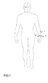
- Figure 1 shows a human body wherefrom a biosignal is measured from the surface of the skin of the body, a biosignal measuring arrangement being attached to the wrist of the body.
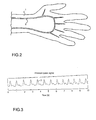
- Figure 2 shows a hand belonging to the body, showing how the wrist artery is located
- Figure 3 shows a pressure pulse signal to be measured by a biosignal measuring arrangement of the invention
- Figure 4 shows the biosignal measuring arrangement of the invention to be attached to the wrist, the arrangement comprising a helical-spring-type element of the invention
- Figure 5 shows the biosignal measuring arrangement of the invention arranged in a wristband as seen from the direction of a cross-section of the wrist
- Figure 6 shows the helical-spring-type element of the biosignal measuring arrangement of the invention
- Figure 7a shows the biosignal measuring arrangement of the invention to be attached to the wrist which comprises the helical-spring-type element of the invention arranged in a clasp of a fastener
- Figure 7b shows the biosignal measuring arrangement of the invention to be attached to the wrist which comprises the helical-spring-type element of the invention arranged to be part of the wristband,
- Figure 8 is a diagram schematically showing the biosignal measuring arrangement of the invention applied to heart rate measurement
- Figure 9 is a diagram schematically showing the biosignal measuring arrangement of the invention applied to blood pressure measurement.
- Figure 10 shows a pressure pulse signal of a blood pressure measurement application and an effective pressing force.
- Figure 1 shows a living human body wherefrom a biosignal is measured from the surface of the skin 1 of the body.
- a biosignal measuring device such as a heart rate monitor, is arranged on the wrist of the person, the device being connected to a fastener 6, such as a casing 5 attached to the wristband 6.
- the living body is represented by a hand belonging to the body, the hand showing how an artery 2, such as a wrist artery 2, is located.
- the signal to be measured is a pressure pulse signal S to be measured from the wrist artery 2, in which case a measuring sensor 300 of the measuring arrangement is a pressure sensor 300.
- the pressure pulse signal is shown in Figure 3.
- Figures 4 and 5 show a measuring arrangement of the heart rate monitor type of the preferred embodiment of the invention wherein all components of the device are arranged in one casing 5.
- reference numbers 12 and 13 designate the radius and the ulna respectively.
- the pressure pulse signal S measured from the wrist artery 2 is measured by the pressure sensor 300.
- the sensor 300 is situated at the wrist artery 2 such that the sensor 300 is located on top of the wrist artery while the sensor 300 is pressed tightly against the surface 1 of the skin in order to obtain as good contact with the artery as possible.
- the contact of the sensor 300 with the surface 1 of the skin may either be direct, in which case the sensor 300 directly touches the surface 1 of the skin, or alternatively, the contact may be indirect, in which case e.g. a plastic strip operating as a pressure transmission element is arranged between the sensor 300 and the surface 1 of the skin.
- the surface of the sensor 300 may be provided with a protecting film made of plastic or rubber to block dust and damp.
- the components of the measuring arrangement are arranged in the casing 5.
- the measuring arrangement is kept in place on the wrist on the surface 1 of the person's skin by the fastener 6, which is preferably a straplike wristband 6.
- the fastener 6 is attached to the casing 5 by a fastening part 8, which is preferably a pin 8.
- the joint thus comprises the pin 8 arranged between the fastener 6 and the casing 5 as well as clamps arranged at the ends of the fastener 6 and the casing 5 and provided with a hole 4 in their transverse direction, the fastening part 8 being arranged through the holes 4.
- the joint also serves as a hinge.
- the fastener 6 is appropriately tightened around the wrist and locked by a clasp 11.
- the fastener 6 may also be a collar comprising two collar halves attached to the casing 5, at least one of the halves being hinged with respect to the casing in order to enable the collar to be set in place.
- the casing 5 comprises an upside 5A and an underside 5B.
- the measuring sensor 300 of the arrangement is then preferably arranged on the underside 5B of the casing 5 which in a normal operating situation is pressed against the measurement target. Furthermore, the measuring sensor 300 is arranged substantially in the vicinity of an upper edge 5D of the casing 5, according to the location of the wrist artery.
- the object of the invention is thus to improve the contact of the sensor 300 with the wrist artery 2.
- the idea of the invention is thus that the arrangement comprises an element 7, which is a spring element comprising lever-like supporting surfaces located at a first end 9 and a second end 10 of the element, and a spring part located therebetween.
- the first end 9 of the element 7 rests on the casing 5 while the second end 10 of the element rests on the fastener 6.
- the element 7 is preferably arranged in the joint between the fastener 6 and the upper edge 5D of the casing 5 such that the element 7 produces a force F which, with respect to the fastener 6, turns the casing 5 substantially towards the measurement target, i.e. the surface 1 of the skin and the artery 2 underneath, thus pressing the upper edge 5D of the casing 5 against the measurement target 1.
- the above-described arrangement is used for directing a pressing force against the surface 1 of the skin and the artery 2 instead of pressing the wrist over the entire area covered by the fastener 6.
- the element 7 is arranged between the casing 5 and the fastener 6 of the measuring arrangement.
- the element 7 rests on a joint pin 8 of a pin joint between the casing 5 and the fastener 6.
- the force needed to improve the artery contact is thus such that the part of the casing 5 where the sensor 300 is located is to be pressed tightly against the surface 1 of the skin.
- the first end 9 of the element 7 rests on the casing 5 while the second end 10 rests on the clasp 11 of the fastener 6.
- the force stored in the spring element of the element 7 is thus transmitted to the edge 5D of the casing 5 which is located at the first end 9 of the element 7 and which comprises the sensor 300 when in its middle part the element 7 rests on the joint pin 8 of the pin joint and when the element 7 uses the clasp 11 of the fastener 6 as its second fulcrum at the second end 10 of the element 7.
- the element 7 is situated in connection with the hinged half of the collar, this half being the one which is situated on the side of the casing 5 where the sensor 300 is arranged.
- the element 7 otherwise operates in a similar manner to that in the case of the strap arrangement in order to achieve as good contact with the artery as possible.
- the element 7 is a spring element.
- the spring element is preferably a helical spring 7A provided with supporting surfaces at its ends 9, 10 to enable the element to rest on the casing 5 and the fastener 6, such as on the clasp 11 of the fastener 6 in the solution of Figures 4, 5 and 6.
- the middle part of the spring element comprises a helix to store the spring force producing the necessary force F directed towards the artery 2.
- the helix in the middle part of the spring element is punctured by the joint pin 8 of the pin joint between the casing 5 and the fastener 6, whereby the spring element rests on its place at the joint pin 8, which thus operates as a third fulcrum of the spring element.
- the spring element transmits the pressing power to the end of the casing 5 where the sensor 300 is arranged, resting on the fastener 6 and the joint pin 8 of the pin joint.
- the element 7 may also be a leaf-spring-type 7B spring element.
- the ends of the leaf spring 7B are also provided with spring element supporting surfaces by means of which the element rests on the casing 5 and the fastener 6.
- the middle point of the spring element is shaped such that it can be punctured by the joint pin 8 of the pin joint between the casing 5 and the fastener 6, whereby the spring element rests on its place at the joint pin 8, which thus operates a third fulcrum of the spring element.
- the spring element transmits the pressing force to the upper edge 5D of the casing 5 where the sensor 300 is arranged and presses the sensor 300 against the measurement target 1, resting on the fastener 6 and the joint pin 8 of the pin joint.
- the structure of the element 7B may also be such that the supporting surface of the spring element of the leaf spring 7B located at the end of the fastener 6 rests on the fastener 6, e.g. on the clasp 11 of the fastener 6.
- the supporting surface of the leaf spring 7B at the end of the casing 5 is arranged to rest on the casing 5.
- the leaf spring 7B then preferably comprises a structural part which is pre-bent or shaped such that when set in its proper place it transmits to the casing 5 a force which is with respect to the fastener 6 directed substantially towards the measurement target, i.e. the surface 1 of the skin and the artery 2 underneath, thus pressing the upper edge 5D of the casing 5 against the measurement target 1.
- the leaf spring 7B may be made of plastic or metal.
- Figure 7B shows a measuring arrangement of the invention wherein the casing 5 and the fastener 6 constitute an integral whole.
- the joint between the casing 5 and the fastener 6 at the end 5D of the casing 5 comprising the measuring sensor 300 is provided with a leaf-spring-type spring element 7C.
- the leaf spring 7C is then a pre-bent plastic structure shaped such that the spring mechanism 7C is directly integrated in the structure of the casing-fastener entity.
- the supporting surface of the element 7C located at the end of the fastener 6 rests on the fastener 6 while the supporting surface of the element 7C located at the end of the casing 5 is rests on the casing 5.
- the element 7C at the joint between the casing 5 and the fastener 6 bends, the element 7C resisting this bending; consequently, the element 7C transmits to the casing 5 a force which is with respect to the fastener 6 directed substantially towards the measurement target, i.e. the surface 1 of the skin and the artery 2 underneath, thus pressing the upper edge 5D of the casing 5 against the measurement target 1.
- the fastener 6 is preferably a wristband to be attached to the wrist.
- the wristband may then resemble a strap, collar or the like.
- the element 7 is supported at the fastening pin 8 of the fastener 6.
- the casing 5 of the measuring arrangement of the preferred embodiment of the invention is attached around the wrist by the fastener 6 such that the casing 5 and the sensor 300 resting thereon are placed on the underside of the wrist, i.e. on the side where the wrist artery 2 is located in the human wrist.
- the casing 5 is then preferably placed on the underside of the wrist as far as using the measuring device is concerned.
- the casing 5 is tightened around the wrist by means of the fastener 6.
- the sensor 300 is arranged in a casing to be placed on the underside of the wrist whereas a casing comprising a display device is placed on the upper surface of the wrist.
- the casings are tightened around the wrist by using the same fastener 6.
- the element 7 is then situated between the casing 5 comprising the sensor 300 and the fastener 6 such that the element 7 rests on the joint pin 8 of the pin joint between the casing and the fastener 6 in a similar manner to that in connection with the embodiment comprising only one casing.
- Data transmission between the casing comprising the sensor 300 and the other casing comprising the display device can be implemented by using wired data transmission utilizing wires arranged between the casings.
- Another alternative is to use wireless data transmission between the casings based e.g. on using inductive data transmission or a radio signal by employing e.g. technology called Bluetooth.
- the invention can be applied primarily to small personal heart rate monitors to be worn on the wrist.
- the measuring arrangement in Figures 4 and 5 is a measuring arrangement used in a heart rate monitor to be attached to a person's wrist or somewhere else in the body.
- the wristband in Figures 4 and 5 is designated by reference number 6.
- the pressure sensor 300 measures the pressure pulse of the artery 2 from the surface 1 of the skin of the human body, and a heart rate value is calculated on the basis of this pulse.
- the measuring arrangement is then a measuring arrangement for measuring the pressure pulse of the artery 2 from the surface 1 of the skin of the human body.
- the measuring arrangement then comprises a determining means 400 for determining the heart beat value on the basis of the measurement of the pressure pulse of the artery 2.
- signal modifying elements known per se or otherwise, such as a filter 401, an amplifier 402 and an A/D converter 403.
- the filter 401 in Figure 8 is a band-pass filter.
- the pass band of the band-pass filter is preferably located within an area of 1 to 10 Hz.
- the filter 401 and the amplifier 402 implement an analogue pre-stage.
- the measuring arrangement further comprises the display 410 in connection with the determining means 400 for displaying the heart rate value.
- the determining means 400 counts the number of received pressure pulses per time unit and indicates the heart rate value on the display 410.
- the determining means 400 measures the time intervals of successive pressure pulses, calculates the heart rate on the basis of the received information and indicates the heart rate on the display 410.
- a memory 411 and a transmission connection 412 such as an RS-232 connection or a Bluetooth connection, communicate with the determining means 400, the transmission connection enabling heart rate information to be transmitted to a reader and further e.g. to a personal computer.
- the connection 412 may be used for data transmission in the reverse direction as well.
- Figure 9 shows a preferred embodiment for blood pressure measurement.
- the measuring arrangement is then a measuring arrangement for measuring the pressure pulse of the artery 2 from the surface 1 of the skin of a human body.
- the measuring arrangement further comprises a pulse strength determining means 500 for finding out the strength of the pressure pulse of the artery 2.
- a sensor 601 is connected to the measuring arrangement to measure the strength of the effective pressure generated by a pressure generator 600, which sensor 601 has a wired or wireless connection 602 to the measuring arrangement and which in this application can be considered to be part of the measuring arrangement.
- the effective pressure refers to the pressure which squeezes a blood vessel. When the effective pressure is sufficiently high, the pressure pulse stops, i.e.
- the pressure sensor 300 detects no pressure pulse, in which case no measurement signal will be forwarded to block 500.
- the pressure generator 600 is e.g. a pressure cuff 600 which comprises a pressure pump 600a and a pressure line 600b used for conveying the pressure from the pressure pump 600a to the cuff 600.
- the measuring arrangement also comprises the filter 401, amplifier 402, A/D converter 403, display 410, memory 411 and possibly a data transmission connection 412, such as an RS connection 412.
- a data transmission connection 412 such as an RS connection 412.
- the value of the effective pressure produced by the pressure generator 600, or the information on the basis of which the effective pressure value can be calculated, is transferred from the sensor 601 to the measuring arrangement e.g. through the RS-232 connection 412 or through another wireless or wired data transmission connection.
- the transmission connection is designated by reference number 602.
- the transmission connection 602 may be based e.g. on an inductive coupling between blocks 601 and 412.
- the measuring arrangement in Figure 9 further comprises a blood pressure determining means 800 communicating with the pressure pulse strength determining means 500.
- the information obtained from the sensor 601 e.g. through the connection 412, 602 on the strength of the effective pressure is also routed to the blood pressure determining means 800.
- the blood pressure determining means 800 determines a blood pressure value on the basis of the signal of the sensor 601 measuring the strength of the effective pressure, the blood pressure value being displayed on the display 410 of the measuring arrangement.
- the blood pressure determining means 800 determines, i.e.
- a diastolic pressure PDIAS value is the same as the value of the effective pressure at the particular moment obtained from the sensor 601.
- the blood pressure value determining means 800 determines that a systolic pressure PSYS value is the same as the value of the effective pressure at the particular moment obtained from the sensor 601.
- said varying effective pressure is an ascending effective pressure.
- the blood pressure is thus measured when the effective pressure is being raised by the pressure generator 600.
- the measurement is more convenient to the person being measured during the ascending pressure since the effective pressure does not have to be raised too high.
- the diastolic pressure PDIAS is determined on the basis of a strength of the effective pressure which prevails when in the pressure pulse measurement, e.g. during the measurement of the pressure pulse amplitude in blocks 500 and 800, it is detected that the strength of the pressure pulse, i.e. the amplitude, starts decreasing.
- the systolic pressure PSYS is determined on the basis of a strength of the effective pressure which prevails when in the measurement of the pressure pulse, e.g. during the measurement of the pressure pulse amplitude in blocks 500 and 800, it is detected that the pressure pulse amplitude stops decreasing.
- the method is most preferably such that in the measurement carried out during the ascending effective pressure, the diastolic pressure PDIAS is determined on the basis of the effective pressure of the same strength which prevails when during the measurement of the pressure pulse, e.g. in the measurement of the pressure pulse amplitude, it is detected that the substantially constant value of the pressure pulse, such as an amplitude with a constant value, starts decreasing substantially directly linearly.
- the systolic pressure PSYS is determined on the basis of the strength of the effective pressure which prevails when in the measurement of the pressure pulse amplitude it is detected that the amplitude of the substantially directly linearly descending pressure pulse stops decreasing and reaches its minimum value AMIN substantially corresponding to zero.
- the pulse strength determining means 500 enables such points to be detected more easily and, additionally, more accurate measurements to be achieved.
- the heart rate value determining means 400, pulse strength determining means 500 and blood pressure value determining means 800 may be implemented by a programmable processor, an ASIC (Application Specific Integrated Circuit) circuit, a separate component or by employing mixed technology, which refers to a combination of two or more above-mentioned techniques.
- ASIC Application Specific Integrated Circuit
- the alternative embodiments disclosed above also apply to the filter 401 and the amplifier 402 which, according to the Applicant's view, can be implemented extremely well by the ASIC technology, although e.g. operational amplifiers, resistors and capacitors may alternatively be used as well.
- the display 410 is e.g. a matrix display.
- blocks 401, 402 and 410 to 412 may be implemented in a similar manner to that shown for blocks 401, 402 and 410 to 412 in Figure 8.
- Blocks 500 and 800 differ most from block 400 since block 500, compared to block 400, must also be able to find out the strength of the pressure pulse signal at any given moment in place of or in addition to mere calculation of the number of pulses (or calculation of the length of time intervals between the pulses).
- Block 800 must also to be able to interpret what the change in the output information supplied by block 500 means. The operation of block 800 is thus controlled by rules which, in accordance with Figure 10, indicate what each change in the output information supplied by block 500 means.
- the senor 300 is connected to the filter 401 wherein the signal is filtered.
- the filter 401 in turn, is connected to an intermediate amplifier 402 which amplifies the filtered signal.
- the intermediate repeater 402 in turn, is connected to an A/D converter 403 which converts an analogue signal into a digital one.
- the A/D converter in turn, is connected to the processor 400/500/800.
Landscapes
- Health & Medical Sciences (AREA)
- Life Sciences & Earth Sciences (AREA)
- Medical Informatics (AREA)
- Molecular Biology (AREA)
- Veterinary Medicine (AREA)
- Biophysics (AREA)
- Pathology (AREA)
- Engineering & Computer Science (AREA)
- Biomedical Technology (AREA)
- Heart & Thoracic Surgery (AREA)
- Public Health (AREA)
- Physics & Mathematics (AREA)
- Surgery (AREA)
- Animal Behavior & Ethology (AREA)
- General Health & Medical Sciences (AREA)
- Cardiology (AREA)
- Physiology (AREA)
- Measuring Pulse, Heart Rate, Blood Pressure Or Blood Flow (AREA)
- Measurement Of The Respiration, Hearing Ability, Form, And Blood Characteristics Of Living Organisms (AREA)
- Investigating Or Analysing Biological Materials (AREA)
- Investigating Or Analysing Materials By The Use Of Chemical Reactions (AREA)
- Measuring And Recording Apparatus For Diagnosis (AREA)
Applications Claiming Priority (2)
| Application Number | Priority Date | Filing Date | Title |
|---|---|---|---|
| FI20000346A FI20000346A7 (fi) | 2000-02-16 | 2000-02-16 | Järjestely biosignaalin mittaamiseksi |
| FI20000346 | 2000-02-16 |
Publications (3)
| Publication Number | Publication Date |
|---|---|
| EP1125547A2 true EP1125547A2 (de) | 2001-08-22 |
| EP1125547A3 EP1125547A3 (de) | 2002-08-21 |
| EP1125547B1 EP1125547B1 (de) | 2006-05-10 |
Family
ID=8557553
Family Applications (1)
| Application Number | Title | Priority Date | Filing Date |
|---|---|---|---|
| EP01000011A Expired - Lifetime EP1125547B1 (de) | 2000-02-16 | 2001-02-08 | Anordnung zur Messung von Biosignalen |
Country Status (5)
| Country | Link |
|---|---|
| US (1) | US6520920B2 (de) |
| EP (1) | EP1125547B1 (de) |
| AT (1) | ATE325578T1 (de) |
| DE (1) | DE60119402T2 (de) |
| FI (1) | FI20000346A7 (de) |
Families Citing this family (26)
| Publication number | Priority date | Publication date | Assignee | Title |
|---|---|---|---|---|
| DE10008792A1 (de) * | 2000-02-18 | 2001-08-23 | Biotronik Mess & Therapieg | Vorrichtung zur Verarbeitung von Körpersignalen |
| US20030163051A1 (en) * | 2002-02-25 | 2003-08-28 | Colin Corporation | Systems and methods for measuring pulse wave velocity and augmentation index |
| US20040073123A1 (en) * | 2002-10-11 | 2004-04-15 | Hessel Stephen R. | Apparatus and methods for non-invasively measuring hemodynamic parameters |
| US7341561B2 (en) * | 2003-05-30 | 2008-03-11 | Casio Computer Co., Ltd. | Wrist-worn high-accuracy pulsation measuring apparatus |
| US7314450B2 (en) * | 2003-08-29 | 2008-01-01 | Casio Computer Co., Ltd. | Wearable heartbeat measuring device, system and method |
| US20060041200A1 (en) * | 2004-06-04 | 2006-02-23 | Dotter James E | Physiological sensor device |
| US20070106132A1 (en) * | 2004-09-28 | 2007-05-10 | Elhag Sammy I | Monitoring device, method and system |
| US20060079794A1 (en) * | 2004-09-28 | 2006-04-13 | Impact Sports Technologies, Inc. | Monitoring device, method and system |
| US20060253010A1 (en) * | 2004-09-28 | 2006-11-09 | Donald Brady | Monitoring device, method and system |
| US7887492B1 (en) | 2004-09-28 | 2011-02-15 | Impact Sports Technologies, Inc. | Monitoring device, method and system |
| US7946994B2 (en) | 2004-10-07 | 2011-05-24 | Tensys Medical, Inc. | Compact apparatus and methods for non-invasively measuring hemodynamic parameters |
| US7530954B2 (en) * | 2005-09-08 | 2009-05-12 | The Vlahos Family Trust | Method and apparatus for identifying the valid systolic blood pressure of a person with hardened arteries |
| US20070142715A1 (en) * | 2005-12-20 | 2007-06-21 | Triage Wireless, Inc. | Chest strap for measuring vital signs |
| CA2655049A1 (en) | 2006-05-13 | 2007-11-22 | Tensys Medical, Inc. | Continuous positioning apparatus and methods |
| USD544961S1 (en) | 2006-06-06 | 2007-06-19 | Impact Sports Technologies, Inc. | Heart rate monitor |
| US20080021334A1 (en) * | 2006-07-19 | 2008-01-24 | Finburgh Simon E | Apparatus and methods for non-invasively measuring hemodynamic parameters |
| JP2008119198A (ja) * | 2006-11-10 | 2008-05-29 | Tokai Rika Co Ltd | 状況改善助言装置 |
| US20080319327A1 (en) * | 2007-06-25 | 2008-12-25 | Triage Wireless, Inc. | Body-worn sensor featuring a low-power processor and multi-sensor array for measuring blood pressure |
| CN101896117B (zh) | 2007-10-12 | 2015-03-04 | 坦西斯医药股份有限公司 | 用于非侵入式测量病人动脉血压的设备和方法 |
| CH699319A2 (de) * | 2008-08-15 | 2010-02-15 | Stbl Medical Res Gmbh | Verfahren und Gerät zum kontinuierlichen Messen des Blutdruckes zu Überwachungszwecken. |
| US20100185398A1 (en) * | 2009-01-22 | 2010-07-22 | Under Armour, Inc. | System and Method for Monitoring Athletic Performance |
| CN102755151A (zh) * | 2011-04-27 | 2012-10-31 | 深圳市迈迪加科技发展有限公司 | 一种心脏功能监测方法 |
| US9655530B2 (en) | 2011-04-29 | 2017-05-23 | Tensys Medical, Inc. | Apparatus and methods for non-invasively measuring physiologic parameters of one or more subjects |
| CN104013396B (zh) * | 2014-03-31 | 2015-12-02 | 肖殿清 | 一种舌压式血压计 |
| JP2014166561A (ja) * | 2014-04-23 | 2014-09-11 | Seiko Epson Corp | 血圧計 |
| CN112450906B (zh) * | 2019-09-09 | 2025-04-11 | 马克西姆综合产品公司 | 具有受控的压力斜坡的测量系统 |
Family Cites Families (10)
| Publication number | Priority date | Publication date | Assignee | Title |
|---|---|---|---|---|
| US4307727A (en) | 1979-10-15 | 1981-12-29 | Tech Engineering And Design, Inc. | Wrist band transducer support and tensioning apparatus |
| EP0333442A1 (de) * | 1988-03-14 | 1989-09-20 | Colin Electronics Co., Ltd. | Impulswellendetektorgerät |
| US5243992A (en) * | 1990-03-30 | 1993-09-14 | Colin Electronics Co., Ltd. | Pulse rate sensor system |
| US5240007A (en) * | 1991-05-14 | 1993-08-31 | Ivac Corporation | Apparatus and method for moving a tissue stress sensor for applanating an artery |
| FI95535C (fi) * | 1991-12-09 | 1996-02-26 | Polar Electro Oy | Laite sydänsykkeen mittaukseen |
| US5590649A (en) * | 1994-04-15 | 1997-01-07 | Vital Insite, Inc. | Apparatus and method for measuring an induced perturbation to determine blood pressure |
| US5908027A (en) * | 1994-08-22 | 1999-06-01 | Alaris Medical Systems, Inc. | Tonometry system for monitoring blood pressure |
| US5640964A (en) * | 1995-02-16 | 1997-06-24 | Medwave, Inc. | Wrist mounted blood pressure sensor |
| US5738800A (en) * | 1996-09-27 | 1998-04-14 | Rodel, Inc. | Composition and method for polishing a composite of silica and silicon nitride |
| JPH10146322A (ja) * | 1996-11-18 | 1998-06-02 | Nippon Colin Co Ltd | 頸動脈波検出装置 |
-
2000
- 2000-02-16 FI FI20000346A patent/FI20000346A7/fi unknown
-
2001
- 2001-02-08 DE DE60119402T patent/DE60119402T2/de not_active Expired - Fee Related
- 2001-02-08 EP EP01000011A patent/EP1125547B1/de not_active Expired - Lifetime
- 2001-02-08 AT AT01000011T patent/ATE325578T1/de not_active IP Right Cessation
- 2001-02-15 US US09/783,788 patent/US6520920B2/en not_active Expired - Fee Related
Non-Patent Citations (1)
| Title |
|---|
| None |
Also Published As
| Publication number | Publication date |
|---|---|
| US6520920B2 (en) | 2003-02-18 |
| EP1125547A3 (de) | 2002-08-21 |
| FI20000346L (fi) | 2001-08-16 |
| ATE325578T1 (de) | 2006-06-15 |
| FI20000346A7 (fi) | 2001-08-17 |
| US20010020134A1 (en) | 2001-09-06 |
| EP1125547B1 (de) | 2006-05-10 |
| DE60119402D1 (de) | 2006-06-14 |
| DE60119402T2 (de) | 2006-10-19 |
| FI20000346A0 (fi) | 2000-02-16 |
Similar Documents
| Publication | Publication Date | Title |
|---|---|---|
| US6520920B2 (en) | Arrangement for measuring biosignal | |
| US6443905B1 (en) | Method and arrangement for blood pressure measurement | |
| CN100560019C (zh) | 脉搏波传输时间法测量动脉血压的初始校准装置 | |
| US5267566A (en) | Apparatus and method for blood pressure monitoring | |
| US6558335B1 (en) | Wrist-mounted blood pressure measurement device | |
| US7361148B2 (en) | Cuff volumetric pulse wave obtaining apparatus, cuff volumetric pulse wave analyzing apparatus, pressure pulse wave obtaining apparatus, and pressure pulse wave analyzing apparatus | |
| US6843772B2 (en) | Inferior-and-superior-limb blood-pressure-index measuring apparatus | |
| CN100586366C (zh) | 腕带式人体血压无创连续检测装置 | |
| US5682898A (en) | Respiration rate measuring apparatus | |
| AU2005211992B2 (en) | Apparatus and method for measuring hemodynamic parameters | |
| US6241679B1 (en) | Non-invasive blood pressure sensing device and method using transducer with associate memory | |
| US6554773B1 (en) | Method and arrangement for blood pressure measurement | |
| US7270636B2 (en) | Apparatus and method for pulse detection | |
| WO2000074563A1 (en) | Method and device for arterial blood pressure measurement | |
| EP1264573A3 (de) | Blutdruckmessgerät mit Herzfunktionserfassung | |
| US20090012411A1 (en) | Method and apparatus for obtaining electronic oscillotory pressure signals from an inflatable blood pressure cuff | |
| KR100957298B1 (ko) | 생체정보계측장치 | |
| US6808497B2 (en) | Blood-pressure measuring apparatus and inferior-and-superior-limb blood-pressure-index measuring apparatus | |
| JPWO2000003636A1 (ja) | 電子血圧計及び血圧の測定方法 | |
| KR102272019B1 (ko) | 혈압 측정 시스템 및 이를 이용한 혈압 측정 방법 | |
| HK1037508A (en) | Arrangement for measuring biosignal | |
| US20020147403A1 (en) | Pulse-wave-propagation-velocity measuring apparatus | |
| US20030167011A1 (en) | Standard pulse-wave-propagation-velocity-related-value determining apparatus and pulse-wave-propagation-velocity-related-value obtaining apparatus | |
| EP1334692A2 (de) | Blutdruckindexmessgerät der oberen und unteren Glieder | |
| JP6837881B2 (ja) | 生体情報測定装置、方法及びプログラム |
Legal Events
| Date | Code | Title | Description |
|---|---|---|---|
| PUAI | Public reference made under article 153(3) epc to a published international application that has entered the european phase |
Free format text: ORIGINAL CODE: 0009012 |
|
| AK | Designated contracting states |
Kind code of ref document: A2 Designated state(s): AT BE CH CY DE DK ES FI FR GB GR IE IT LI LU MC NL PT SE TR |
|
| AX | Request for extension of the european patent |
Free format text: AL;LT;LV;MK;RO;SI |
|
| PUAL | Search report despatched |
Free format text: ORIGINAL CODE: 0009013 |
|
| AK | Designated contracting states |
Kind code of ref document: A3 Designated state(s): AT BE CH CY DE DK ES FI FR GB GR IE IT LI LU MC NL PT SE TR |
|
| AX | Request for extension of the european patent |
Free format text: AL;LT;LV;MK;RO;SI |
|
| 17P | Request for examination filed |
Effective date: 20030116 |
|
| AKX | Designation fees paid |
Designated state(s): AT BE CH CY DE DK ES FI FR GB GR IE IT LI LU MC NL PT SE TR |
|
| 17Q | First examination report despatched |
Effective date: 20050413 |
|
| GRAP | Despatch of communication of intention to grant a patent |
Free format text: ORIGINAL CODE: EPIDOSNIGR1 |
|
| GRAS | Grant fee paid |
Free format text: ORIGINAL CODE: EPIDOSNIGR3 |
|
| GRAA | (expected) grant |
Free format text: ORIGINAL CODE: 0009210 |
|
| AK | Designated contracting states |
Kind code of ref document: B1 Designated state(s): AT BE CH CY DE DK ES FI FR GB GR IE IT LI LU MC NL PT SE TR |
|
| PG25 | Lapsed in a contracting state [announced via postgrant information from national office to epo] |
Ref country code: NL Free format text: LAPSE BECAUSE OF FAILURE TO SUBMIT A TRANSLATION OF THE DESCRIPTION OR TO PAY THE FEE WITHIN THE PRESCRIBED TIME-LIMIT Effective date: 20060510 Ref country code: CH Free format text: LAPSE BECAUSE OF FAILURE TO SUBMIT A TRANSLATION OF THE DESCRIPTION OR TO PAY THE FEE WITHIN THE PRESCRIBED TIME-LIMIT Effective date: 20060510 Ref country code: FI Free format text: LAPSE BECAUSE OF FAILURE TO SUBMIT A TRANSLATION OF THE DESCRIPTION OR TO PAY THE FEE WITHIN THE PRESCRIBED TIME-LIMIT Effective date: 20060510 Ref country code: BE Free format text: LAPSE BECAUSE OF FAILURE TO SUBMIT A TRANSLATION OF THE DESCRIPTION OR TO PAY THE FEE WITHIN THE PRESCRIBED TIME-LIMIT Effective date: 20060510 Ref country code: LI Free format text: LAPSE BECAUSE OF FAILURE TO SUBMIT A TRANSLATION OF THE DESCRIPTION OR TO PAY THE FEE WITHIN THE PRESCRIBED TIME-LIMIT Effective date: 20060510 Ref country code: AT Free format text: LAPSE BECAUSE OF FAILURE TO SUBMIT A TRANSLATION OF THE DESCRIPTION OR TO PAY THE FEE WITHIN THE PRESCRIBED TIME-LIMIT Effective date: 20060510 Ref country code: IT Free format text: LAPSE BECAUSE OF FAILURE TO SUBMIT A TRANSLATION OF THE DESCRIPTION OR TO PAY THE FEE WITHIN THE PRESCRIBED TIME-LIMIT;WARNING: LAPSES OF ITALIAN PATENTS WITH EFFECTIVE DATE BEFORE 2007 MAY HAVE OCCURRED AT ANY TIME BEFORE 2007. THE CORRECT EFFECTIVE DATE MAY BE DIFFERENT FROM THE ONE RECORDED. Effective date: 20060510 |
|
| REG | Reference to a national code |
Ref country code: GB Ref legal event code: FG4D |
|
| REG | Reference to a national code |
Ref country code: CH Ref legal event code: EP |
|
| REF | Corresponds to: |
Ref document number: 60119402 Country of ref document: DE Date of ref document: 20060614 Kind code of ref document: P |
|
| REG | Reference to a national code |
Ref country code: IE Ref legal event code: FG4D |
|
| PG25 | Lapsed in a contracting state [announced via postgrant information from national office to epo] |
Ref country code: SE Free format text: LAPSE BECAUSE OF FAILURE TO SUBMIT A TRANSLATION OF THE DESCRIPTION OR TO PAY THE FEE WITHIN THE PRESCRIBED TIME-LIMIT Effective date: 20060810 Ref country code: DK Free format text: LAPSE BECAUSE OF FAILURE TO SUBMIT A TRANSLATION OF THE DESCRIPTION OR TO PAY THE FEE WITHIN THE PRESCRIBED TIME-LIMIT Effective date: 20060810 |
|
| PG25 | Lapsed in a contracting state [announced via postgrant information from national office to epo] |
Ref country code: ES Free format text: LAPSE BECAUSE OF FAILURE TO SUBMIT A TRANSLATION OF THE DESCRIPTION OR TO PAY THE FEE WITHIN THE PRESCRIBED TIME-LIMIT Effective date: 20060821 |
|
| PG25 | Lapsed in a contracting state [announced via postgrant information from national office to epo] |
Ref country code: PT Free format text: LAPSE BECAUSE OF FAILURE TO SUBMIT A TRANSLATION OF THE DESCRIPTION OR TO PAY THE FEE WITHIN THE PRESCRIBED TIME-LIMIT Effective date: 20061010 |
|
| NLV1 | Nl: lapsed or annulled due to failure to fulfill the requirements of art. 29p and 29m of the patents act | ||
| REG | Reference to a national code |
Ref country code: CH Ref legal event code: PL |
|
| PG25 | Lapsed in a contracting state [announced via postgrant information from national office to epo] |
Ref country code: MC Free format text: LAPSE BECAUSE OF NON-PAYMENT OF DUE FEES Effective date: 20070228 |
|
| PLBE | No opposition filed within time limit |
Free format text: ORIGINAL CODE: 0009261 |
|
| STAA | Information on the status of an ep patent application or granted ep patent |
Free format text: STATUS: NO OPPOSITION FILED WITHIN TIME LIMIT |
|
| 26N | No opposition filed |
Effective date: 20070213 |
|
| EN | Fr: translation not filed | ||
| PG25 | Lapsed in a contracting state [announced via postgrant information from national office to epo] |
Ref country code: IE Free format text: LAPSE BECAUSE OF NON-PAYMENT OF DUE FEES Effective date: 20070208 |
|
| PG25 | Lapsed in a contracting state [announced via postgrant information from national office to epo] |
Ref country code: GR Free format text: LAPSE BECAUSE OF FAILURE TO SUBMIT A TRANSLATION OF THE DESCRIPTION OR TO PAY THE FEE WITHIN THE PRESCRIBED TIME-LIMIT Effective date: 20060811 Ref country code: FR Free format text: LAPSE BECAUSE OF FAILURE TO SUBMIT A TRANSLATION OF THE DESCRIPTION OR TO PAY THE FEE WITHIN THE PRESCRIBED TIME-LIMIT Effective date: 20070309 |
|
| PGFP | Annual fee paid to national office [announced via postgrant information from national office to epo] |
Ref country code: DE Payment date: 20080219 Year of fee payment: 8 Ref country code: GB Payment date: 20080221 Year of fee payment: 8 |
|
| REG | Reference to a national code |
Ref country code: HK Ref legal event code: WD Ref document number: 1037508 Country of ref document: HK |
|
| PG25 | Lapsed in a contracting state [announced via postgrant information from national office to epo] |
Ref country code: FR Free format text: LAPSE BECAUSE OF FAILURE TO SUBMIT A TRANSLATION OF THE DESCRIPTION OR TO PAY THE FEE WITHIN THE PRESCRIBED TIME-LIMIT Effective date: 20060510 |
|
| PG25 | Lapsed in a contracting state [announced via postgrant information from national office to epo] |
Ref country code: LU Free format text: LAPSE BECAUSE OF NON-PAYMENT OF DUE FEES Effective date: 20070208 Ref country code: CY Free format text: LAPSE BECAUSE OF FAILURE TO SUBMIT A TRANSLATION OF THE DESCRIPTION OR TO PAY THE FEE WITHIN THE PRESCRIBED TIME-LIMIT Effective date: 20060510 |
|
| PG25 | Lapsed in a contracting state [announced via postgrant information from national office to epo] |
Ref country code: TR Free format text: LAPSE BECAUSE OF FAILURE TO SUBMIT A TRANSLATION OF THE DESCRIPTION OR TO PAY THE FEE WITHIN THE PRESCRIBED TIME-LIMIT Effective date: 20060510 |
|
| GBPC | Gb: european patent ceased through non-payment of renewal fee |
Effective date: 20090208 |
|
| PG25 | Lapsed in a contracting state [announced via postgrant information from national office to epo] |
Ref country code: DE Free format text: LAPSE BECAUSE OF NON-PAYMENT OF DUE FEES Effective date: 20090901 |
|
| PG25 | Lapsed in a contracting state [announced via postgrant information from national office to epo] |
Ref country code: GB Free format text: LAPSE BECAUSE OF NON-PAYMENT OF DUE FEES Effective date: 20090208 |