EP1125596B1 - Intravaskulärer Katheter - Google Patents
Intravaskulärer Katheter Download PDFInfo
- Publication number
- EP1125596B1 EP1125596B1 EP01301049A EP01301049A EP1125596B1 EP 1125596 B1 EP1125596 B1 EP 1125596B1 EP 01301049 A EP01301049 A EP 01301049A EP 01301049 A EP01301049 A EP 01301049A EP 1125596 B1 EP1125596 B1 EP 1125596B1
- Authority
- EP
- European Patent Office
- Prior art keywords
- catheter
- wings
- resin member
- flexible resin
- wing
- Prior art date
- Legal status (The legal status is an assumption and is not a legal conclusion. Google has not performed a legal analysis and makes no representation as to the accuracy of the status listed.)
- Expired - Lifetime
Links
- 229920005989 resin Polymers 0.000 claims abstract description 83
- 239000011347 resin Substances 0.000 claims abstract description 83
- 239000008280 blood Substances 0.000 claims abstract description 32
- 210000004369 blood Anatomy 0.000 claims abstract description 32
- 239000000853 adhesive Substances 0.000 claims description 6
- 230000001070 adhesive effect Effects 0.000 claims description 6
- 238000003825 pressing Methods 0.000 claims description 6
- 230000004927 fusion Effects 0.000 claims description 5
- 230000008602 contraction Effects 0.000 claims description 3
- 238000003466 welding Methods 0.000 claims description 2
- 230000000295 complement effect Effects 0.000 claims 1
- 230000007246 mechanism Effects 0.000 abstract description 23
- 230000002265 prevention Effects 0.000 abstract description 6
- 238000000034 method Methods 0.000 description 25
- 239000000463 material Substances 0.000 description 19
- 210000004204 blood vessel Anatomy 0.000 description 14
- -1 polyethylenes Polymers 0.000 description 13
- 229920002803 thermoplastic polyurethane Polymers 0.000 description 11
- PPBRXRYQALVLMV-UHFFFAOYSA-N Styrene Chemical compound C=CC1=CC=CC=C1 PPBRXRYQALVLMV-UHFFFAOYSA-N 0.000 description 10
- 239000007788 liquid Substances 0.000 description 10
- 239000004698 Polyethylene Substances 0.000 description 7
- 229920002589 poly(vinylethylene) polymer Polymers 0.000 description 7
- 229920000573 polyethylene Polymers 0.000 description 7
- 239000004677 Nylon Substances 0.000 description 6
- 239000004743 Polypropylene Substances 0.000 description 6
- 229920001778 nylon Polymers 0.000 description 6
- 229920001155 polypropylene Polymers 0.000 description 6
- 239000004800 polyvinyl chloride Substances 0.000 description 6
- 229920000915 polyvinyl chloride Polymers 0.000 description 6
- 229920002050 silicone resin Polymers 0.000 description 6
- 244000043261 Hevea brasiliensis Species 0.000 description 5
- 239000013013 elastic material Substances 0.000 description 5
- 229920001971 elastomer Polymers 0.000 description 5
- 239000000806 elastomer Substances 0.000 description 5
- 239000000203 mixture Substances 0.000 description 5
- 229920003052 natural elastomer Polymers 0.000 description 5
- 229920001194 natural rubber Polymers 0.000 description 5
- 229920006124 polyolefin elastomer Polymers 0.000 description 5
- 230000017531 blood circulation Effects 0.000 description 4
- 238000007796 conventional method Methods 0.000 description 4
- 238000010586 diagram Methods 0.000 description 4
- 238000003780 insertion Methods 0.000 description 4
- 230000037431 insertion Effects 0.000 description 4
- 238000001723 curing Methods 0.000 description 3
- 239000003814 drug Substances 0.000 description 3
- 238000001746 injection moulding Methods 0.000 description 3
- 229910052751 metal Inorganic materials 0.000 description 3
- 239000002184 metal Substances 0.000 description 3
- 230000000452 restraining effect Effects 0.000 description 3
- XEEYBQQBJWHFJM-UHFFFAOYSA-N Iron Chemical compound [Fe] XEEYBQQBJWHFJM-UHFFFAOYSA-N 0.000 description 2
- 230000000694 effects Effects 0.000 description 2
- 238000001125 extrusion Methods 0.000 description 2
- 238000010438 heat treatment Methods 0.000 description 2
- 230000010354 integration Effects 0.000 description 2
- 238000004519 manufacturing process Methods 0.000 description 2
- 239000003960 organic solvent Substances 0.000 description 2
- 230000003014 reinforcing effect Effects 0.000 description 2
- 230000008961 swelling Effects 0.000 description 2
- RYGMFSIKBFXOCR-UHFFFAOYSA-N Copper Chemical compound [Cu] RYGMFSIKBFXOCR-UHFFFAOYSA-N 0.000 description 1
- 208000032767 Device breakage Diseases 0.000 description 1
- YCKRFDGAMUMZLT-UHFFFAOYSA-N Fluorine atom Chemical compound [F] YCKRFDGAMUMZLT-UHFFFAOYSA-N 0.000 description 1
- 239000004642 Polyimide Substances 0.000 description 1
- BQCADISMDOOEFD-UHFFFAOYSA-N Silver Chemical compound [Ag] BQCADISMDOOEFD-UHFFFAOYSA-N 0.000 description 1
- 208000007536 Thrombosis Diseases 0.000 description 1
- 239000000956 alloy Substances 0.000 description 1
- 229910045601 alloy Inorganic materials 0.000 description 1
- 229910052782 aluminium Inorganic materials 0.000 description 1
- XAGFODPZIPBFFR-UHFFFAOYSA-N aluminium Chemical compound [Al] XAGFODPZIPBFFR-UHFFFAOYSA-N 0.000 description 1
- 210000001367 artery Anatomy 0.000 description 1
- 238000005452 bending Methods 0.000 description 1
- 229920005549 butyl rubber Polymers 0.000 description 1
- 230000006835 compression Effects 0.000 description 1
- 238000007906 compression Methods 0.000 description 1
- 239000012141 concentrate Substances 0.000 description 1
- 229910052802 copper Inorganic materials 0.000 description 1
- 239000010949 copper Substances 0.000 description 1
- 238000000502 dialysis Methods 0.000 description 1
- 229920006351 engineering plastic Polymers 0.000 description 1
- 239000011737 fluorine Substances 0.000 description 1
- 229910052731 fluorine Inorganic materials 0.000 description 1
- 230000006698 induction Effects 0.000 description 1
- 238000001361 intraarterial administration Methods 0.000 description 1
- 238000001990 intravenous administration Methods 0.000 description 1
- 229910052742 iron Inorganic materials 0.000 description 1
- 150000002739 metals Chemical class 0.000 description 1
- 238000000465 moulding Methods 0.000 description 1
- 238000000016 photochemical curing Methods 0.000 description 1
- 229920002492 poly(sulfone) Polymers 0.000 description 1
- 239000004417 polycarbonate Substances 0.000 description 1
- 229920000515 polycarbonate Polymers 0.000 description 1
- 229920001225 polyester resin Polymers 0.000 description 1
- 239000004645 polyester resin Substances 0.000 description 1
- 229920006393 polyether sulfone Polymers 0.000 description 1
- 229920001721 polyimide Polymers 0.000 description 1
- 229920005672 polyolefin resin Polymers 0.000 description 1
- 230000002035 prolonged effect Effects 0.000 description 1
- 230000002285 radioactive effect Effects 0.000 description 1
- 239000003566 sealing material Substances 0.000 description 1
- 229910052709 silver Inorganic materials 0.000 description 1
- 239000004332 silver Substances 0.000 description 1
- 239000010935 stainless steel Substances 0.000 description 1
- 229910001220 stainless steel Inorganic materials 0.000 description 1
- 229920005992 thermoplastic resin Polymers 0.000 description 1
- 210000003462 vein Anatomy 0.000 description 1
Images



Classifications
-
- A—HUMAN NECESSITIES
- A61—MEDICAL OR VETERINARY SCIENCE; HYGIENE
- A61M—DEVICES FOR INTRODUCING MEDIA INTO, OR ONTO, THE BODY; DEVICES FOR TRANSDUCING BODY MEDIA OR FOR TAKING MEDIA FROM THE BODY; DEVICES FOR PRODUCING OR ENDING SLEEP OR STUPOR
- A61M25/00—Catheters; Hollow probes
- A61M25/01—Introducing, guiding, advancing, emplacing or holding catheters
- A61M25/06—Body-piercing guide needles or the like
- A61M25/0612—Devices for protecting the needle; Devices to help insertion of the needle, e.g. wings or holders
- A61M25/0637—Butterfly or winged devices, e.g. for facilitating handling or for attachment to the skin
-
- A—HUMAN NECESSITIES
- A61—MEDICAL OR VETERINARY SCIENCE; HYGIENE
- A61M—DEVICES FOR INTRODUCING MEDIA INTO, OR ONTO, THE BODY; DEVICES FOR TRANSDUCING BODY MEDIA OR FOR TAKING MEDIA FROM THE BODY; DEVICES FOR PRODUCING OR ENDING SLEEP OR STUPOR
- A61M39/00—Tubes, tube connectors, tube couplings, valves, access sites or the like, specially adapted for medical use
- A61M39/22—Valves or arrangement of valves
- A61M39/28—Clamping means for squeezing flexible tubes, e.g. roller clamps
- A61M39/284—Lever clamps
Definitions
- the present invention relates to an intravascular catheter provided with a function for controlling the blood flow.
- Insertion of an intravascular catheter in a blood vessel can be confirmed by flashback, that is, the backward flow of the blood at the time of piercing the intravascular catheter into the blood vessel.
- flashback that is, the backward flow of the blood at the time of piercing the intravascular catheter into the blood vessel.
- a problem of leakage of the blood flowing backward arises at the time of pulling out the internal needle.
- a method of stopping the blood by pressing the tip end part or the hub base part of the intravascular catheter a method of preventing the blood leakage by providing an elastic tube at the catheter base end part and pressing the tube part with a finger at the time of pulling out the internal needle, and a method of preventing blood leakage by storing an elastic tube with a swelling in the catheter base end part and pressing the swelling part (U. S. Patent No.
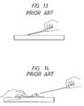
- FIGS. 13 and 14 show the conventional method of restraining the leakage by directly pressuring the catheter part outer surface in the vicinity of the hub base of the intravascular needle with a finger.
- the method of directly pressuring the catheter outer surface is a method of closing the catheter itself by flattening the same with the pressure, there is a risk of breaking the catheter itself by the flattening operation so as to lead to cut-off of the catheter.
- intravascular catheters comprising a means for directly pressing and closing the catheter base end part outer surface (U. S. Patent Nos. 5, 108, 374 and 5, 542, 933) have been proposed, but since the catheter part is pressured directly in these methods, catheter breakage may be brought about.
- a method of providing a blood flow controlling device such as a check valve, a detent plug, and forceps stoppage in an elastic tube part can be presented.
- the methods include a method of further providing an elastic clamp tube part between a hub part at the catheter base end part and a connector part as a part for connecting with an external circuit so as to enable closure with forceps (JP-B-61-25490U, JP-B-6-39724U).
- US-A-5429616 discloses a catheter having a hub containing a tube of resiliently compressible sealing material. Around this tube is a side wall which is collapsed, to compress the tube, by means of grippable locking members which extend tangentially parallel to each other. The locking members may have latch means to lock them in the compression mode.
- US-A-5749859 shows a similar structure in which foldable wings of a hub squeeze a flexible tube.
- EP-A-312073 describes a catheter having a valve with a flexible tubular insert in two portions which are mutually displaceable from their coaxial position by tilting one relative to the other and shaped to compress the tubular insert when so displaced.
- US-A-4198973 shows a catheter having a hub around it to which are attached two projecting wings.
- the wings can be folded together by bending at a hinge line in one wing so that a protuberance on this wing presses on the hub to occlude the catheter.
- the wings can be locked in the folded position.
- EP-A-691139 shows an elastic clip having wings which are pressed and locked together to compress and close a flexible tube, particularly in medical uses.
- an object of the invention is to provide an intravascular catheter capable of closing the catheter part without breaking the catheter part by pressuring the catheter part via a flexible resin member provided on the outer surface of a catheter part, and further comprising a blood leakage prevention member capable of preventing the blood leakage.
- Another object is to provide an intravascular catheter comprising a mechanism for easily fixing or releasing the state with the blood leakage prevented by pressuring and closing the catheter.
- the invention provides an intravascular catheter as set out in claim 1.
- the catheter and the flexible resin member are fixed by one of welding, fusion and an adhesive.
- the flexible resin member is a thermally contractible member, fixed on the catheter part outer surface by thermal contraction.
- a hub is provided on the proximal end of the flexible resin member.
- the flexible resin member has a tubular shape with a rhomboidal cross-sectional shape, the ratio A/B of the thickest part A and the thinnest part B of the tube wall being in the range between 1 and 10.
- the flexible resin member has a tubular shape, with an elliptical cross-sectional shape, the ratio C/D of the longer axis C and the shorter axis D in the range between 1 and 4.
- the invention provides an intravascular catheter comprising a catheter part and an internal needle disposed through the catheter part, with a flexible resin member disposed at the base end part of the catheter part so as to envelop the catheter outer surface.
- a blood leakage prevention means for pressuring and closing the catheter part can be disposed in the intravascular catheter main body in the invention.
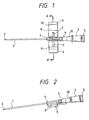
- a catheter part 1 and an internal needle 2 disposed therethrough are provided.
- An internal needle hub 3 is provided at the rear end of the internal needle 2, and a cap 5 containing a blood leakage resistant filter is further disposed on the rear end thereof.
- the position for mounting the flexible resin member onto the catheter is preferably at the catheter base end part.
- the flexible tubular resin member can provide the breakage prevention effect by the stress concentration alleviation, and particularly is the pipe-like member 4 shown in FIGS. 1, 2 and 3 (cross-sectional view taken on the line A-A' in FIG. 1).
- another example of a flexible resin member is a modified pipe-like member including a slit thereon.
- the operativity is further be improved by providing a blood leakage prevention means in the catheter main body.
- a blood leakage prevention means in the catheter main body.
- Examples of mounting the blood leakage prevention means include a provision of wing parts in the catheter main body, and pressure parts in the wing parts.
- the wing parts 6 will be explained specifically with reference to drawings.
- the wing parts are wing-like parts provided between the catheter part and the connector part on the right and left sides.
- the wing parts 6 comprise pressure parts 7.
- the pressure parts 7 provided in the wing parts 6 shown in FIG. 3 comprise projected members, any shape can be adopted as long as it can pressure and close the flexible resin member and the catheter part.
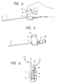
- a fixing mechanism as a means for fixing the pressured state as well as a releasing mechanism as a means for releasing the fixed state are further provided, as set out in claim 1. They are not particularly limited, but mechanisms capable of easily fixing and maintaining the fixed state as well as capable of easily releasing the state like those shown in FIGS. 6 and 7 are further preferable.
- the fixed state can easily be released by nipping a plate-like part 12 provided elongating outside of a nail part of a wing part at one side, and the wing end part 6 so as to lift the nail part. According to this shape, since the fixed state can be set or released by one hand, it is extremely convenient because it cannot prevent the speedy hand of the medical expert.
- a projection-shaped part and a recess-shaped part are provided each on the right and left wings so as to achieve fixation of the closed state by fitting the projection part and the recess part.
- the shape of the wing parts is developed into a substantially flat plate-like shape at the time of releasing the fixation in the above-mentioned embodiments of the wing parts
- a shape of the wing parts with the rolled state maintained without being spread into a substantially flat plate-like shape at the time of releasing fixation can also be adopted as shown in FIGS. 9(A) to 9(D).
- the pressure parts including the wing parts will be explained.
- the pressure parts are parts for deforming the flexible resin member and the catheter part.
- they can be projected members including the wing parts, disposed on the right and left wings at symmetrical positions.
- the flexible resin member is formed integrally with the catheter part or the connector part, since a connection part between the parts can be eliminated, pulling off of the flexible resin member from the catheter part or the connector part can be avoided even if they are pulled by some causes. Moreover, since the gap in the internal space can be reduced, eccentric flow or stagnation can hardly be generated in the blood flow, and thus generation of thrombus can be prevented.
- FIGS. 11(A) and 11(B) closure of the pressure parts can be facilitated, and thus it is further effective.
- a ratio A/B of the thickest part A and the thinnest part B in the range between 1 and 10 is effective. With a smaller ratio, the strength of the thinnest thick part is weak so that the strength of the flexible resin member cannot be maintained; therefore, it is not preferable.
- a ratio C/D of the longer axis C and the shorter axis D in the range between 1 and 4 is effective.
- the flexible resin member is flattened too much so that the channel is so narrow that the smooth flow of the blood or the transfusion liquid can hardly be ensured; therefore, it is not preferable.
- a hub part 9 can be disposed at the base end side (proximal side) of the flexible resin member 4, 11 as shown in FIGS. 1 and 2.
- the hub 9 can be provided of the same material or continuously with the catheter 1 and the flexible resin member 4 and 11.
- a connector part 10 is provided at the rear end part of the hub part 9.
- the connector part can be provided either of the same material or continuously with the hub part 9, but it is more preferable that it is provided continuously therewith.
- the hub part is a part for bonding the catheter part and the connector part, and the connector part is a part for connecting the intravascular catheter and an external transfusion liquid circuit.
- the intravascular catheter according to the invention including the components in the order of the flexible resin member, the hub part, and the connector part can achieve integration of the hub part and the connector part provided adjacently because the flexible resin member is provided onward with respect to the hub part so that the number of parts can be reduced so as to achieve the compactness as well as the operativity and the handling convenience can further be improved.
- the hub part 9 can preferably adopted as shown in FIGS. 1 and 2, but it is not limited thereto. That is, it can be the catheter part 1, the flexible resin member 4, 11, or the like, and thus it is not particularly limited as long as it can be fixed to the main body.
- the tip end of the internal needle 2 is pierced into the blood vessel.
- the catheter 1 With the internal needle 2 serving as the guide, the catheter 1 is inserted into the blood vessel. Insertion of the internal needle 2 into the blood vessel can be confirmed by flow-out of the blood through the internal needle 2 from the rear end of the internal needle of the internal needle hub 3. Moreover, leakage of the blood flown out to the outside can be prevented by a blood leakage resistant filter of a cap 5 provided at the rear end of the internal hub 3.
- the internal needle 2 After insertion of the catheter 1 into the blood vessel, the internal needle 2 is taken out from the blood vessel and the catheter 1. In this case, pressure on the wing parts 6 by fingers is released slightly for facilitating the pull-out of the internal needle 2.
- the pressured and closed state can be released by releasing the pressure by the fingers or releasing the fixed state by the releasing mechanism 12 in the case where it is fixed by the fixing mechanism 8 so that the wing parts 6 are spread in the initial state so as to fix the wing parts 6 onto the skin surface with a tape.
- the invention can be applied in an intravenous needle, an intra-arterial needle, and a dialyzing needle. Furthermore, it can be applied in an introducer kit and an IVH catheter kit, but it is not limited thereto.
- FIGS. 1, 5, and 12 An embodiment of the operation method as the introducer kit will be described with reference to FIGS. 1, 5, and 12.
- the wing parts 6 With the internal needle 2 inserted as shown in FIG. 1, the wing parts 6 are nipped by fingers for inserting the catheter into the blood vessel with the flexible resin member 4 and the internal needle 2 gripped by the pressure parts 7. After pulling out the internal needle, the wing parts 6 are further pressured so as to close the flexible resin member 4.
- the fixing mechanism 8 so as to be in the state of FIG. 5, the blood leakage is restrained.
- the guide wire 316 is introduced with the pressure by the pressure parts gradually released by fingers of one hand.
- the guide wire 316 can be introduced into the blood vessel while restraining the blood leakage due to backward flow from the blood vessel as shown in FIG. 12.
- thermoplastic resins such as fluorine resins, urethane resins, nylon resins, polyester resins, polyethylenes, and polypropylenes are preferable, but it is not limited thereto.
- the flexible resin member can be made from the same material as the catheter part and the hub part. Furthermore, it can be provided continuously with the hub part.
- flexible resins such as olefin-based elastomers including 1,2-polybutadiene, styrene-based elastomers, urethane resins, polyethylenes, polypropylenes, nylon resins, silicone resins, polyvinyl chloride resins, natural rubbers, and mixtures thereof can be used. Since butyl rubbers and urethane resins can easily alleviate the stress concentrated on the pressure parts, they are preferable for the capability of preventing breakage of the catheter in the pressured and closed state further effectively, but it is not limited thereto.
- urethane resins are used for the materials of both catheter part and flexible resin member, by using a urethane resin having a higher elasticity for the flexible resin member compared with that of the catheter part, release of the pressured and closed state by the fixing mechanism part can be executed smoothly.
- flexible resins that is, the materials same as that of the flexible resin member, the hub part, and the connector part
- examples thereof include olefin-based elastomers including 1,2-polybutadiene, styrene-based elastomers, urethane resins, polyethylenes, polypropylenes, nylon resins, silicone resins, polyvinyl chloride resins, natural rubbers, and mixtures thereof, but it is not limited thereto.
- both elastic materials and non-elastic materials can be used. Furthermore, it can either be same as or different form the material of the wing parts.
- the elastic materials include olefin-based elastomers including 1,2-polybutadiene, styrene-based elastomers, urethane resins, polyethylenes, polypropylenes, nylon resins, silicone resins, polyvinyl chloride resins, natural rubbers, and mixtures thereof, but it is not limited thereto.
- non-elastic materials examples include engineering plastics such as polysulfones, polyether sulfones, polycarbonates, and polyimides, but it is not limited thereto.
- engineering plastics such as polysulfones, polyether sulfones, polycarbonates, and polyimides, but it is not limited thereto.
- metals or alloys such as iron, silver, copper, aluminum and stainless steel can also be used.
- the hub part is a part for connecting the catheter part with the connector part, it can be provided continuously with the catheter part or the flexible resin part.
- the material thereof can be flexible resins, that is, the materials same as that of the flexible resin member. Examples thereof include olefin-based elastomers including 1,2-polybutadiene, styrene-based elastomers, urethane resins, polyethylenes, polypropylenes, nylon resins, silicone resins, polyvinyl chloride resins, natural rubbers, and mixtures thereof, but it is not limited thereto.
- the connector part is a part for connecting with the liquid circuit for a medicine liquid or a transfusion liquid, it can be provided continuously with the hub part.
- the material thereof can be flexible resins, that is, the materials same as that of the flexible resin member. Examples thereof include olefin-based elastomers including 1,2-polybutadiene, styrene-based elastomers, urethane resins, polyethylenes, polypropylenes, nylon resins, silicone resins, polyvinyl chloride resins, natural rubbers, and mixtures thereof, but it is not limited thereto.
- a method for bonding the catheter part 1 and the flexible resin member a method of injecting an adhesive into a gap part between the outer surface of the catheter part and the inner surface of the flexible resin member , and curing can be presented.
- a method of preliminarily applying an adhesive on the outer surface of the catheter part, placing the flexible resin member thereon, and curing can be presented.
- a photo-curing adhesive and a method of directing a radioactive ray from an opening part or from the outside for curing can be presented, but it is not limited thereto.
- adhesion using an organic solvent is also possible .
- adhesion can be completed by dropping a few drops of an organic solvent; therefore, the operation can be simple.
- a member made from a thermally contractible material can be used as the flexible resin member.
- a method of placing a thermally contractible member having an inner diameter larger than the catheter outer diameter on the catheter outer surface, and causing the thermal contraction in an oven or by a drier for fixation on the catheter outer surface can be presented. Since the method is simpler than the method using an adhesion or thermal fusion, it is further preferable, but it is not limited thereto.
- the thermally contractible member include thermally contractible members having the elasticity, such as those containing an olefin resin, a polyvinyl chloride resin, and a silicone resin, but it is not limited thereto.
- the catheter part 1 is produced by extrusion molding from, for example, a urethane resin into a flexible tube member having a outer diameter of 0.3 to 20 mm and a thickness of 0.08 to 5 mm, with the inner diameter thereof slightly larger than the outer diameter of the blood vessel piercing internal needle 2 to be introduced therein, and the base end thereof connected with the hub part 9.
- the hub part 9 produced by injection molding from, for example, 1,2-polybutadiene, is fitted with the flexible resin member 4 .
- the flexible resin member 4 is produced by extrusion molding or injection molding from, for example, 1,2-polybutadiene.
- the size of the flexible resin member 4 and the wing parts 6 is changed accordingly.
- an outer diameter of 1.0 to 40 mm, a thickness of 0.08 to 10 mm, and a length of 3 to 100 mm can be adopted.
- an outer diameter of 1.2 to 30 mm, a thickness of 0.1 to 8 mm, and a length of 5.0 to 80 mm are further preferable.
- a pair of the flexible wings 6 produced by injection molding from a polyethylene elongate symmetrically on both right and left ends of the flexible resin member 4 in the direction substantially orthogonal to the axial direction of the catheter.
- the width of the wing parts 6 is 2 to 80 mm, and the length from the main body side to the end part is 5 to 100 mm. It is further preferable that the wing width is 3 to 70 mm, and the length from the main body side to the end part is 8 to 80 mm.
- the pressure parts 7 are formed preferably integrally with the wing parts on the upper surface of the wing parts 6.
- the height of the pressure parts is 0.8 to 50 mm, and is further preferably 1.0 to 40 mm.
- the flexible resin member including a reinforcing tubular or pipe-like member capable of alleviating stress concentration is provided in the catheter part for pressuring and closing the catheter part therefrom, the stress can be alleviated compared with the conventional case of directly pressuring and closing the catheter part so that blood leakage can be prevented without generating breakage or cut-off of the catheter.
- the pressure parts are provided for pressuring and closing via the flexible resin member, breakage or cut-off of the catheter according to the excessive pressure by metal forceps in the conventional method can be restrained. Moreover, since the pressure parts are provided in the intravascular catheter main body, an extra closing device needs not be prepared as well as the operation of taking out the internal needle is facilitated compared with the conventional method.
- the fixing mechanism capable of fixing the pressured state since the fixing mechanism capable of fixing the pressured state is provided, freedom of use of both hands necessary in the subsequent operation of connecting the external circuit such as a medicine liquid and a transfusion liquid is ensured. Moreover, since the releasing mechanism capable of easily releasing the fixed state is provided, the fixed state can be released without giving a pain to the patient. Since the pressure parts, the fixing mechanism and the releasing mechanism are provided integrally with the wing parts, a compact configuration, a good operativity, and improved economy and productivity can be achieved without giving a pain to the patient at the time of closing the catheter by pressing thereto as in the conventional method.
- the flexible resin member since the hub part is provided at the base end side of the flexible resin member, the flexible resin member needs not be disposed between the hub part and the connector part so that the hub part and the connector part are provided adjacently for allowing the integration. Accordingly, the number of parts is reduced so that the productivity and economy are improved as well as the entire length is shortened to achieve the compactness and improve the handling convenience.
- the flexible resin member is bonded with the catheter part, the catheter restoration force after being released from the pressured and closed state can be improved. Furthermore, in the case where the flexible resin member is made from a thermally contractible material, it can be fixed on the outer surface of the catheter without the need of using an adhesive.
- the catheter is used as the introducer kit for introducing an external catheter such as a guide wire
- blood leakage after taking out the internal needle can be prevented as well as, since the wing parts can be fixed and maintained in the closed state, blood leakage can be restrained at the time of introducing the external catheter such as a guide wire by nipping the wing parts for pressuring the flexible resin pipe-like member.
Landscapes
- Health & Medical Sciences (AREA)
- Heart & Thoracic Surgery (AREA)
- Life Sciences & Earth Sciences (AREA)
- Hematology (AREA)
- Engineering & Computer Science (AREA)
- Anesthesiology (AREA)
- Biomedical Technology (AREA)
- Pulmonology (AREA)
- Animal Behavior & Ethology (AREA)
- General Health & Medical Sciences (AREA)
- Public Health (AREA)
- Veterinary Medicine (AREA)
- Biophysics (AREA)
- Media Introduction/Drainage Providing Device (AREA)
- Infusion, Injection, And Reservoir Apparatuses (AREA)
- Materials For Medical Uses (AREA)
Claims (7)
- Intravaskulärer Katheter mit:dadurch gekennzeichnet, dasseinem Katheter (1);einer Innennadel (2), die durch den Katheter (1) hindurch angeordnet ist;einem Blutaustrittsverhinderungselement zum Verhindern eines Austretens von Blut durch ein Zusammendrücken des Katheters (1), wobei das Blutaustrittsverhinderungselement einen ersten und einen zweiten Flügel (6) hat, die an jeder Seite von dem Katheter (1) angeordnet sind, wobei die Flügel jeweils eine Druckeinrichtung (7) haben, um einen Druck von entgegengesetzten Seiten dann aufzubringen, wenn die Flügel zusammengedrückt werden, wodurch der Katheter (1) zusammengedrückt wird; undeiner lösbaren Fixiereinrichtung (8) für ein Fixieren der Druckeinrichtung (7) in einem mit Druck beaufschlagten Zustand, bei dem der Katheter (1) zusammengedrückt ist, und wobei sie lösbar ist, um die Druckeinrichtung (7) aus dem mit Druck beaufschlagten Zustand zu entlasten,
ein flexibles röhrenartigen Harzelement (4) die Außenfläche von dem Katheter (1) umgibt;
die Flügel (6), wenn sie zusammengedrückt sind, das röhrenartige Harzelement (4) zwischen ihnen zusammendrücken; und wobei
die lösbare Fixiereinrichtung folgendes aufweist:entweder(a) ein Vorsprungselement (8, 12), das durch einen ersten Flügel (6) getragen ist und sich in der gleichen Richtung wie der erste Flügel erstreckt, wobei das Vorsprungselement Folgendes aufweist:ein Fixierende (8), das mit einem Fixierelement (8) an dem anderen Flügel in Eingriff bringbar ist, um die Flügel in dem mit Druck beaufschlagten Zustand zu arretieren, undeinen Plattenabschnitt (12), der zu dem ersten Flügel hin zusammendrückbar ist, um das Fixierende (8) anzuheben, um den mit Druck beaufschlagten Zustand zu entlasten; oder(b) komplementäre Zubehörteile mit einem Vorsprung bzw. mit einer Vertiefung, wobei ein Teil an jedem Flügel (6) vorgesehen ist, wobei die Druckeinrichtung (7) in dem mit Druck beaufschlagten Zustand durch den Eingriff des mit dem Vorsprung versehenen Zubehörteiles mit dem mit der Vertiefung versehenen Zubehörteil fixierbar ist; oder(c) einem Paar an miteinander in Eingriff bringbaren Einrastelementen jeweils an den Flügeln, die in Eingriff bringbar sind, um die Flügel in dem mit Druck beaufschlagten Zustand zu arretieren, wobei die Flügel eine Rollenform haben sowohl wenn sie freigegeben sind als auch in dem mit Druck beaufschlagten Zustand, wobei die Einrastelemente freigegeben werden, indem die Flügel zueinander gedrückt werden. - Intravaskulärer Katheter gemäß Anspruch 1, wobei zumindest entweder die Druckeinrichtung (7) oder die lösbare Fixiereinrichtung (8) mit den Flügeln (6) einstückig ist.
- Intravaskulärer Katheter gemäß einem der Ansprüche 1 oder 2, wobei
der Katheter (1) und das flexible Harzelement (4) fixiert sind durch ein Schweißen, Kleben oder ein Haftmittel. - Intravaskulärer Katheter gemäß einem der Ansprüche 1 oder 2, wobei
das flexible Harzelement (4) ein thermisch kontrahierbares Element ist, das an der Außenfläche des Katheters (1) durch thermisches Kontrahieren befestigt ist. - Intravaskulärer Katheter gemäß einem der vorherigen Ansprüche, wobei
eine Buchse (9) an dem proximalen Ende von dem flexiblen Harzelement (4) vorgesehen ist. - Intravaskulärer Katheter gemäß einem der vorherigen Ansprüche, wobei
das flexible Harzelement (4) eine röhrenartige Form mit rhomboidartigen Querschnittsform hat, wobei das Verhältnis A/B der Dicke von dem dicksten Teil A der Röhrenwand und dem dünnsten Teil B der Röhrenwand in dem Bereich zwischen 1 und 10 liegt. - Intravaskulärer Katheter gemäß einem der Ansprüche 1 bis 5, wobei
das flexible Harzelement (4) eine röhrenartige Form mit einer elliptischen Querschnittsform hat, wobei das Verhältnis C/D von der längeren Achse C und der kürzeren Achse D in dem Bereich zwischen 1 und 4 liegt.
Applications Claiming Priority (2)
| Application Number | Priority Date | Filing Date | Title |
|---|---|---|---|
| JP2000038725 | 2000-02-16 | ||
| JP2000038725A JP4472824B2 (ja) | 2000-02-16 | 2000-02-16 | 血管内留置カテーテル |
Publications (3)
| Publication Number | Publication Date |
|---|---|
| EP1125596A2 EP1125596A2 (de) | 2001-08-22 |
| EP1125596A3 EP1125596A3 (de) | 2002-05-08 |
| EP1125596B1 true EP1125596B1 (de) | 2005-05-11 |
Family
ID=18562419
Family Applications (1)
| Application Number | Title | Priority Date | Filing Date |
|---|---|---|---|
| EP01301049A Expired - Lifetime EP1125596B1 (de) | 2000-02-16 | 2001-02-06 | Intravaskulärer Katheter |
Country Status (5)
| Country | Link |
|---|---|
| US (1) | US6482180B2 (de) |
| EP (1) | EP1125596B1 (de) |
| JP (1) | JP4472824B2 (de) |
| AT (1) | ATE295199T1 (de) |
| DE (1) | DE60110651T2 (de) |
Families Citing this family (29)
| Publication number | Priority date | Publication date | Assignee | Title |
|---|---|---|---|---|
| WO2003045489A1 (fr) * | 2001-11-26 | 2003-06-05 | Urawa Kenkyusho Private Ltd. Co. | File-guide et son procede de production |
| US8262639B2 (en) | 2002-01-31 | 2012-09-11 | Fenwal, Inc. | Irreversible flow control clamp |
| DE60334067D1 (de) | 2002-01-31 | 2010-10-21 | Fenwal Inc | Irreversibel schliessbare stromregelklemme |
| US7384416B2 (en) * | 2002-08-12 | 2008-06-10 | Macopharma | Device and method for irreversible closure of fluid communication in a container system |
| US7344527B2 (en) * | 2003-11-19 | 2008-03-18 | Medical Components, Inc. | Luer with integrated clamp |
| FR2886857B1 (fr) * | 2005-06-08 | 2008-04-18 | Perouse Soc Par Actions Simpli | Dispositif d'injection d'un liquide dans un patient |
| FR2916979B1 (fr) * | 2007-06-07 | 2010-10-22 | Perouse Lab | Dispositif d'injection d'un liquide dans un corps. |
| USD620107S1 (en) * | 2007-09-17 | 2010-07-20 | Q Park Medical Limited | Endoscope sheath assembly |
| FR2923392B1 (fr) * | 2007-11-14 | 2010-03-26 | M2Ct Sarl | Dispositif a pression positive pour la chimiotherapie par action simultanee de 2 composants alternativement comprimes. |
| US8323251B2 (en) | 2008-01-14 | 2012-12-04 | Fenwal, Inc. | Phlebotomy needle assembly and frangible cover |
| WO2010062637A1 (en) | 2008-10-28 | 2010-06-03 | Medical Components, Inc. | Clamp for flexible tubing |
| MY163971A (en) * | 2009-10-01 | 2017-11-15 | Braun Melsungen Ag | Catheter insertion device |
| JP5836931B2 (ja) | 2010-03-26 | 2015-12-24 | テルモ株式会社 | 留置針組立体 |
| WO2011161054A1 (en) * | 2010-06-24 | 2011-12-29 | Gambro Lundia Ab | Blood access device |
| US8652104B2 (en) | 2010-06-25 | 2014-02-18 | Smiths Medical Asd, Inc. | Catheter assembly with seal member |
| US9028425B2 (en) * | 2010-07-15 | 2015-05-12 | Becton, Dickinson And Company | Vented blood sampling device |
| BR112013019691A2 (pt) * | 2011-02-03 | 2017-03-21 | H Lee Moffitt Cancer Ct & Res | braçadeiras de cateter e cateteres |
| GB201203426D0 (en) * | 2012-02-28 | 2012-04-11 | Renishaw Plc | Neurosurgical apparatus |
| US9833606B2 (en) | 2012-09-07 | 2017-12-05 | Fenwal, Inc. | Non-reopenable flow control clamp |
| US10252023B2 (en) * | 2013-01-11 | 2019-04-09 | C. R. Bard, Inc. | Curved catheter and methods for making same |
| EP3295986B1 (de) | 2015-05-15 | 2025-07-23 | Terumo Kabushiki Kaisha | Katheteranordnung |
| EP4353297A3 (de) * | 2016-02-18 | 2024-07-24 | Smiths Medical ASD, Inc. | Katheter mit geschlossenem system |
| KR101707181B1 (ko) * | 2016-02-25 | 2017-02-15 | 김정규 | 안전 카테터 조립체 |
| WO2018133028A1 (zh) * | 2017-01-20 | 2018-07-26 | 福建省百仕韦医用高分子股份有限公司 | 外置敷翼的护套型留置针 |
| CN108273175B (zh) * | 2018-01-23 | 2020-11-10 | 葛俊丽 | 一种输血介入导管的固定装置 |
| CA3098894A1 (en) | 2018-05-01 | 2019-11-07 | Becton, Dickinson And Company | Squeeze activated blood collection set |
| CN119949936A (zh) * | 2018-12-10 | 2025-05-09 | 阿利迪亚保健公司 | 止血装置 |
| WO2021025992A1 (en) | 2019-08-07 | 2021-02-11 | Hollister Incorporated | Urinary catheter drainage members and catheters having the same |
| JP7576607B2 (ja) * | 2020-02-20 | 2024-10-31 | テルモ株式会社 | カテーテル組立体 |
Family Cites Families (20)
| Publication number | Priority date | Publication date | Assignee | Title |
|---|---|---|---|---|
| US3856010A (en) | 1971-08-09 | 1974-12-24 | Deseret Pharma | Catheter placement unit with pressure closure |
| US4198973A (en) * | 1978-03-14 | 1980-04-22 | Johnson & Johnson | Intravenous catheter assembly with fluid flow restriction capability |
| JPS6125490A (ja) | 1984-07-13 | 1986-02-04 | Kyowa Hakko Kogyo Co Ltd | 補酵素q10の製造法 |
| US4834719A (en) | 1986-04-28 | 1989-05-30 | Cordis Corporation | Quick connect/disconnect tubing adapter |
| US4687176A (en) * | 1986-07-07 | 1987-08-18 | Olsen C Eric | Flow control valve for a flexible walled tube |
| JPS6415308A (en) | 1987-07-08 | 1989-01-19 | Nippon Kokan Kk | Apparatus for producing metal powder |
| DE3734894C1 (de) * | 1987-10-15 | 1989-01-26 | Braun Melsungen Ag | Ansatzstueck mit Ventil |
| US5167635A (en) * | 1989-09-22 | 1992-12-01 | Habley Medical Technology Corporation | Compact, easy to assemble, safety IV system |
| US5108374A (en) | 1990-05-02 | 1992-04-28 | Critikon, Inc. | Stickless catheter with manual shut-off valve |
| US5542933A (en) | 1992-06-15 | 1996-08-06 | Marks; Ronald | Catheter valve |
| JPH0639724A (ja) | 1992-07-27 | 1994-02-15 | Yoshikawa Kogyo Co Ltd | アブレイシブウォータージェット加工における研削材回収装置 |
| US5270003A (en) * | 1992-11-20 | 1993-12-14 | Baxter International Inc. | Blood sampling system |
| AUPM289593A0 (en) * | 1993-12-10 | 1994-01-06 | Powell, Andrew Robert | A catheter/cannula system |
| US5354281A (en) * | 1994-03-25 | 1994-10-11 | Chen Shih Shuan | Safety disposable infusion set |
| US5429616A (en) * | 1994-05-31 | 1995-07-04 | Schaffer; David I. | Occludable catheter |
| IT235145Y1 (it) * | 1994-07-07 | 2000-03-31 | Cgm Spa | Pinzetta elastica per chiudere piccoli tubi flessibili |
| JPH08141078A (ja) | 1994-11-21 | 1996-06-04 | Ikufumi Yamada | 外部から圧迫出来る血管内留置針 |
| US5498241A (en) * | 1994-12-08 | 1996-03-12 | Abbott Laboratories | Winged needle assembly with protective member |
| US5674201A (en) * | 1995-03-16 | 1997-10-07 | Becton Dickinson And Company | Rotatable catheter housed within a flexible wing assembly |
| CA2169220A1 (en) * | 1995-03-16 | 1996-09-17 | Greg L. Brimhall | Control forward introducer needle and catheter assembly |
-
2000
- 2000-02-16 JP JP2000038725A patent/JP4472824B2/ja not_active Expired - Fee Related
-
2001
- 2001-02-06 EP EP01301049A patent/EP1125596B1/de not_active Expired - Lifetime
- 2001-02-06 DE DE60110651T patent/DE60110651T2/de not_active Expired - Lifetime
- 2001-02-06 AT AT01301049T patent/ATE295199T1/de not_active IP Right Cessation
- 2001-02-06 US US09/776,923 patent/US6482180B2/en not_active Expired - Lifetime
Also Published As
| Publication number | Publication date |
|---|---|
| EP1125596A2 (de) | 2001-08-22 |
| US20010014787A1 (en) | 2001-08-16 |
| JP4472824B2 (ja) | 2010-06-02 |
| US6482180B2 (en) | 2002-11-19 |
| JP2001224693A (ja) | 2001-08-21 |
| DE60110651T2 (de) | 2006-05-04 |
| ATE295199T1 (de) | 2005-05-15 |
| DE60110651D1 (de) | 2005-06-16 |
| EP1125596A3 (de) | 2002-05-08 |
Similar Documents
| Publication | Publication Date | Title |
|---|---|---|
| EP1125596B1 (de) | Intravaskulärer Katheter | |
| CN100475285C (zh) | 留置针组合体 | |
| US4198973A (en) | Intravenous catheter assembly with fluid flow restriction capability | |
| US6949104B2 (en) | Guide wire steering handle | |
| JP5005548B2 (ja) | ガイドワイヤ・アドバンサー組立体 | |
| AU675749B2 (en) | A catheter or cannula system | |
| US4192304A (en) | Intravenous catheter assembly with fluid flow restriction capability | |
| EP1862193B1 (de) | Verweilkanülenvorrichtung | |
| US4006744A (en) | Locking cannula mount | |
| US6551281B1 (en) | Guide wire advancer and assembly and method for advancing a guide wire | |
| US20090088722A1 (en) | Straight Insertion Safety Infusion Set | |
| CN101321549B (zh) | 留置针组合体 | |
| US5921969A (en) | Apparatus for shielding a butterfly needle | |
| US4504269A (en) | Device for catheterization in particular for perfusions in the medical and veterinary fields | |
| JPWO2007132732A1 (ja) | 留置針組立体 | |
| EP1758634A1 (de) | Röhrenförmige elementenfixiervorrichtung | |
| US5417670A (en) | Puncture needle device, mainly for a closed system introduction of a catheter into a blood vessel | |
| CN101296718B (zh) | 留置针组合体 | |
| WO2007052656A1 (ja) | 留置針組立体 | |
| CN209221155U (zh) | 针头套件和护针器 | |
| CN222549972U (zh) | 一种用于介入治疗的医用三通阀组件 | |
| KR102347245B1 (ko) | 커넥터 일체형 클램프 어셈블리 | |
| JP2003000726A (ja) | コネクター | |
| WO1990006147A1 (en) | A fitting for a hypodermic syringe and a hypodermic syringe arrangement | |
| HK1113470A (en) | Straight insertion safety infusion set |
Legal Events
| Date | Code | Title | Description |
|---|---|---|---|
| PUAI | Public reference made under article 153(3) epc to a published international application that has entered the european phase |
Free format text: ORIGINAL CODE: 0009012 |
|
| AK | Designated contracting states |
Kind code of ref document: A2 Designated state(s): AT BE CH CY DE DK ES FI FR GB GR IE IT LI LU MC NL PT SE TR |
|
| AX | Request for extension of the european patent |
Free format text: AL;LT;LV;MK;RO;SI |
|
| PUAL | Search report despatched |
Free format text: ORIGINAL CODE: 0009013 |
|
| AK | Designated contracting states |
Kind code of ref document: A3 Designated state(s): AT BE CH CY DE DK ES FI FR GB GR IE IT LI LU MC NL PT SE TR |
|
| AX | Request for extension of the european patent |
Free format text: AL;LT;LV;MK;RO;SI |
|
| RIC1 | Information provided on ipc code assigned before grant |
Free format text: 7A 61M 25/06 A, 7A 61M 39/06 B, 7A 61M 39/28 B |
|
| 17P | Request for examination filed |
Effective date: 20020902 |
|
| 17Q | First examination report despatched |
Effective date: 20021115 |
|
| AKX | Designation fees paid |
Designated state(s): AT BE CH CY DE DK ES FI FR GB GR IE IT LI LU MC NL PT SE TR |
|
| GRAP | Despatch of communication of intention to grant a patent |
Free format text: ORIGINAL CODE: EPIDOSNIGR1 |
|
| GRAS | Grant fee paid |
Free format text: ORIGINAL CODE: EPIDOSNIGR3 |
|
| GRAA | (expected) grant |
Free format text: ORIGINAL CODE: 0009210 |
|
| AK | Designated contracting states |
Kind code of ref document: B1 Designated state(s): AT BE CH CY DE DK ES FI FR GB GR IE IT LI LU MC NL PT SE TR |
|
| PG25 | Lapsed in a contracting state [announced via postgrant information from national office to epo] |
Ref country code: AT Free format text: LAPSE BECAUSE OF FAILURE TO SUBMIT A TRANSLATION OF THE DESCRIPTION OR TO PAY THE FEE WITHIN THE PRESCRIBED TIME-LIMIT Effective date: 20050511 Ref country code: NL Free format text: LAPSE BECAUSE OF FAILURE TO SUBMIT A TRANSLATION OF THE DESCRIPTION OR TO PAY THE FEE WITHIN THE PRESCRIBED TIME-LIMIT Effective date: 20050511 Ref country code: BE Free format text: LAPSE BECAUSE OF FAILURE TO SUBMIT A TRANSLATION OF THE DESCRIPTION OR TO PAY THE FEE WITHIN THE PRESCRIBED TIME-LIMIT Effective date: 20050511 Ref country code: CH Free format text: LAPSE BECAUSE OF FAILURE TO SUBMIT A TRANSLATION OF THE DESCRIPTION OR TO PAY THE FEE WITHIN THE PRESCRIBED TIME-LIMIT Effective date: 20050511 Ref country code: LI Free format text: LAPSE BECAUSE OF FAILURE TO SUBMIT A TRANSLATION OF THE DESCRIPTION OR TO PAY THE FEE WITHIN THE PRESCRIBED TIME-LIMIT Effective date: 20050511 Ref country code: FI Free format text: LAPSE BECAUSE OF FAILURE TO SUBMIT A TRANSLATION OF THE DESCRIPTION OR TO PAY THE FEE WITHIN THE PRESCRIBED TIME-LIMIT Effective date: 20050511 Ref country code: IT Free format text: LAPSE BECAUSE OF FAILURE TO SUBMIT A TRANSLATION OF THE DESCRIPTION OR TO PAY THE FEE WITHIN THE PRESCRIBED TIME-LIMIT;WARNING: LAPSES OF ITALIAN PATENTS WITH EFFECTIVE DATE BEFORE 2007 MAY HAVE OCCURRED AT ANY TIME BEFORE 2007. THE CORRECT EFFECTIVE DATE MAY BE DIFFERENT FROM THE ONE RECORDED. Effective date: 20050511 |
|
| REG | Reference to a national code |
Ref country code: GB Ref legal event code: FG4D |
|
| REG | Reference to a national code |
Ref country code: CH Ref legal event code: EP |
|
| REG | Reference to a national code |
Ref country code: IE Ref legal event code: FG4D |
|
| REF | Corresponds to: |
Ref document number: 60110651 Country of ref document: DE Date of ref document: 20050616 Kind code of ref document: P |
|
| PG25 | Lapsed in a contracting state [announced via postgrant information from national office to epo] |
Ref country code: SE Free format text: LAPSE BECAUSE OF FAILURE TO SUBMIT A TRANSLATION OF THE DESCRIPTION OR TO PAY THE FEE WITHIN THE PRESCRIBED TIME-LIMIT Effective date: 20050811 Ref country code: DK Free format text: LAPSE BECAUSE OF FAILURE TO SUBMIT A TRANSLATION OF THE DESCRIPTION OR TO PAY THE FEE WITHIN THE PRESCRIBED TIME-LIMIT Effective date: 20050811 Ref country code: GR Free format text: LAPSE BECAUSE OF FAILURE TO SUBMIT A TRANSLATION OF THE DESCRIPTION OR TO PAY THE FEE WITHIN THE PRESCRIBED TIME-LIMIT Effective date: 20050811 |
|
| PG25 | Lapsed in a contracting state [announced via postgrant information from national office to epo] |
Ref country code: ES Free format text: LAPSE BECAUSE OF FAILURE TO SUBMIT A TRANSLATION OF THE DESCRIPTION OR TO PAY THE FEE WITHIN THE PRESCRIBED TIME-LIMIT Effective date: 20050822 |
|
| PG25 | Lapsed in a contracting state [announced via postgrant information from national office to epo] |
Ref country code: PT Free format text: LAPSE BECAUSE OF FAILURE TO SUBMIT A TRANSLATION OF THE DESCRIPTION OR TO PAY THE FEE WITHIN THE PRESCRIBED TIME-LIMIT Effective date: 20051019 |
|
| NLV1 | Nl: lapsed or annulled due to failure to fulfill the requirements of art. 29p and 29m of the patents act | ||
| REG | Reference to a national code |
Ref country code: CH Ref legal event code: PL |
|
| PG25 | Lapsed in a contracting state [announced via postgrant information from national office to epo] |
Ref country code: IE Free format text: LAPSE BECAUSE OF NON-PAYMENT OF DUE FEES Effective date: 20060206 |
|
| PG25 | Lapsed in a contracting state [announced via postgrant information from national office to epo] |
Ref country code: MC Free format text: LAPSE BECAUSE OF NON-PAYMENT OF DUE FEES Effective date: 20060228 Ref country code: LU Free format text: LAPSE BECAUSE OF NON-PAYMENT OF DUE FEES Effective date: 20060228 |
|
| ET | Fr: translation filed | ||
| PLBE | No opposition filed within time limit |
Free format text: ORIGINAL CODE: 0009261 |
|
| STAA | Information on the status of an ep patent application or granted ep patent |
Free format text: STATUS: NO OPPOSITION FILED WITHIN TIME LIMIT |
|
| 26N | No opposition filed |
Effective date: 20060214 |
|
| REG | Reference to a national code |
Ref country code: IE Ref legal event code: MM4A |
|
| PG25 | Lapsed in a contracting state [announced via postgrant information from national office to epo] |
Ref country code: TR Free format text: LAPSE BECAUSE OF FAILURE TO SUBMIT A TRANSLATION OF THE DESCRIPTION OR TO PAY THE FEE WITHIN THE PRESCRIBED TIME-LIMIT Effective date: 20050511 |
|
| PG25 | Lapsed in a contracting state [announced via postgrant information from national office to epo] |
Ref country code: CY Free format text: LAPSE BECAUSE OF FAILURE TO SUBMIT A TRANSLATION OF THE DESCRIPTION OR TO PAY THE FEE WITHIN THE PRESCRIBED TIME-LIMIT Effective date: 20050511 |
|
| PGFP | Annual fee paid to national office [announced via postgrant information from national office to epo] |
Ref country code: FR Payment date: 20130301 Year of fee payment: 13 Ref country code: DE Payment date: 20130131 Year of fee payment: 13 Ref country code: GB Payment date: 20130207 Year of fee payment: 13 |
|
| REG | Reference to a national code |
Ref country code: DE Ref legal event code: R119 Ref document number: 60110651 Country of ref document: DE |
|
| GBPC | Gb: european patent ceased through non-payment of renewal fee |
Effective date: 20140206 |
|
| REG | Reference to a national code |
Ref country code: FR Ref legal event code: ST Effective date: 20141031 |
|
| REG | Reference to a national code |
Ref country code: DE Ref legal event code: R119 Ref document number: 60110651 Country of ref document: DE Effective date: 20140902 |
|
| PG25 | Lapsed in a contracting state [announced via postgrant information from national office to epo] |
Ref country code: GB Free format text: LAPSE BECAUSE OF NON-PAYMENT OF DUE FEES Effective date: 20140206 Ref country code: FR Free format text: LAPSE BECAUSE OF NON-PAYMENT OF DUE FEES Effective date: 20140228 Ref country code: DE Free format text: LAPSE BECAUSE OF NON-PAYMENT OF DUE FEES Effective date: 20140902 |