EP1125628A2 - Mischkopf für einen pneumatischen Mischer - Google Patents
Mischkopf für einen pneumatischen Mischer Download PDFInfo
- Publication number
- EP1125628A2 EP1125628A2 EP01102298A EP01102298A EP1125628A2 EP 1125628 A2 EP1125628 A2 EP 1125628A2 EP 01102298 A EP01102298 A EP 01102298A EP 01102298 A EP01102298 A EP 01102298A EP 1125628 A2 EP1125628 A2 EP 1125628A2
- Authority
- EP
- European Patent Office
- Prior art keywords
- ring
- nozzle
- mixing head
- axis
- pressure chamber
- Prior art date
- Legal status (The legal status is an assumption and is not a legal conclusion. Google has not performed a legal analysis and makes no representation as to the accuracy of the status listed.)
- Granted
Links
- 238000007664 blowing Methods 0.000 claims abstract description 10
- 229910000831 Steel Inorganic materials 0.000 claims abstract 4
- 239000010959 steel Substances 0.000 claims abstract 4
- 239000002184 metal Substances 0.000 claims description 6
- 229910052751 metal Inorganic materials 0.000 claims description 6
- 230000000149 penetrating effect Effects 0.000 claims 4
- 230000013011 mating Effects 0.000 claims 1
- 238000004519 manufacturing process Methods 0.000 abstract description 4
- 229910001018 Cast iron Inorganic materials 0.000 abstract description 2
- 239000008187 granular material Substances 0.000 abstract description 2
- 239000000843 powder Substances 0.000 abstract description 2
- 239000000463 material Substances 0.000 description 4
- 239000000203 mixture Substances 0.000 description 4
- VVQNEPGJFQJSBK-UHFFFAOYSA-N Methyl methacrylate Chemical compound COC(=O)C(C)=C VVQNEPGJFQJSBK-UHFFFAOYSA-N 0.000 description 1
- 229920005372 Plexiglas® Polymers 0.000 description 1
- 230000001154 acute effect Effects 0.000 description 1
- 238000005054 agglomeration Methods 0.000 description 1
- 230000002776 aggregation Effects 0.000 description 1
- 230000001174 ascending effect Effects 0.000 description 1
- 230000015572 biosynthetic process Effects 0.000 description 1
- 230000001419 dependent effect Effects 0.000 description 1
- 230000000694 effects Effects 0.000 description 1
- 239000013013 elastic material Substances 0.000 description 1
- 239000000945 filler Substances 0.000 description 1
Images



Classifications
-
- B—PERFORMING OPERATIONS; TRANSPORTING
- B01—PHYSICAL OR CHEMICAL PROCESSES OR APPARATUS IN GENERAL
- B01F—MIXING, e.g. DISSOLVING, EMULSIFYING OR DISPERSING
- B01F25/00—Flow mixers; Mixers for falling materials, e.g. solid particles
- B01F25/30—Injector mixers
- B01F25/31—Injector mixers in conduits or tubes through which the main component flows
- B01F25/314—Injector mixers in conduits or tubes through which the main component flows wherein additional components are introduced at the circumference of the conduit
-
- B—PERFORMING OPERATIONS; TRANSPORTING
- B01—PHYSICAL OR CHEMICAL PROCESSES OR APPARATUS IN GENERAL
- B01F—MIXING, e.g. DISSOLVING, EMULSIFYING OR DISPERSING
- B01F33/00—Other mixers; Mixing plants; Combinations of mixers
- B01F33/40—Mixers using gas or liquid agitation, e.g. with air supply tubes
- B01F33/406—Mixers using gas or liquid agitation, e.g. with air supply tubes in receptacles with gas supply only at the bottom
- B01F33/4061—Mixers using gas or liquid agitation, e.g. with air supply tubes in receptacles with gas supply only at the bottom through orifices arranged around a central cone
-
- B—PERFORMING OPERATIONS; TRANSPORTING
- B29—WORKING OF PLASTICS; WORKING OF SUBSTANCES IN A PLASTIC STATE IN GENERAL
- B29B—PREPARATION OR PRETREATMENT OF THE MATERIAL TO BE SHAPED; MAKING GRANULES OR PREFORMS; RECOVERY OF PLASTICS OR OTHER CONSTITUENTS OF WASTE MATERIAL CONTAINING PLASTICS
- B29B7/00—Mixing; Kneading
- B29B7/02—Mixing; Kneading non-continuous, with mechanical mixing or kneading devices, i.e. batch type
- B29B7/04—Mixing; Kneading non-continuous, with mechanical mixing or kneading devices, i.e. batch type with non-movable mixing or kneading devices
-
- B—PERFORMING OPERATIONS; TRANSPORTING
- B01—PHYSICAL OR CHEMICAL PROCESSES OR APPARATUS IN GENERAL
- B01F—MIXING, e.g. DISSOLVING, EMULSIFYING OR DISPERSING
- B01F25/00—Flow mixers; Mixers for falling materials, e.g. solid particles
- B01F2025/91—Direction of flow or arrangement of feed and discharge openings
- B01F2025/913—Vortex flow, i.e. flow spiraling in a tangential direction and moving in an axial direction
-
- B—PERFORMING OPERATIONS; TRANSPORTING
- B01—PHYSICAL OR CHEMICAL PROCESSES OR APPARATUS IN GENERAL
- B01F—MIXING, e.g. DISSOLVING, EMULSIFYING OR DISPERSING
- B01F23/00—Mixing according to the phases to be mixed, e.g. dispersing or emulsifying
- B01F23/60—Mixing solids with solids
Definitions
- the invention is based on a mixing head, which is known from DE-PS 14 32 030 has become.
- Pneumatic mixers using such mixing heads usually consist of a mixing container with a cylindrical top and conical, narrowing lower part, on the lower edge of which Mixing head is attached.
- the mixing head is over one line or over several Lines connected to a compressed air reservoir, which is connected by a compressor Compressed air is supplied.
- the powder or granular material to be mixed becomes whirled up by several blasts of compressed air. With each impact, the peculiar arrangement of the nozzle channels in the vicinity of the container wall ascending vortex and a vertebral depression in the vicinity of the container axis. This results in a highly intensive mixing effect.
- mixing head forms a thick-walled ring with a U-shaped Cross-section of the near-axis wall, the lower front wall and the outer wall of the Pressure chamber.
- a flange attached to the lower part of a mixing container forms the upper end wall.
- the wall adjacent to the axis is with horizontal, radial blind holes provided that emanate from the pressure chamber. From the closed ends of the Blind holes emanate from nozzle holes, the mouths of which at the top of each other ring-shaped zone of the envelope surface that flares upwards. In each There is a Laval nozzle in the nozzle hole, the axis of which is directed obliquely upwards, so that the air jets that mix in operation are all in the same Move the senses along the inner surface of the mixing container in a spiral.
- the thick-walled ring is made of cast iron and therefore very expensive.
- the intricately shaped, obliquely angled into a conical surface Nozzle holes require a lot of production. Because of the kinked The pressure loss is very high due to the shape of the nozzle channels.
- a lifting and lowerable locking cone In the outlet opening enclosed by the annular mixing head, a lifting and lowerable locking cone attached. In the lowered position, he sits with his Lower edge on the mentioned, conically widening annular zone, at the height of the nozzle orifices. This is important so that among the no flow dead spaces diagonally upwards arise in which nests of unmixed mix could form.
- the outlet opening is released by lifting the closing cone. It is not to overcome only the weight of the material in the mixing container, but depending on the type of material also strong internal forces, the one Bridge formation or agglomeration in the lower area of the material column cause. This often makes it impossible to lift the locking cone made. An expansion of the closing cone when the container is full is such Cases not possible.
- a mixing head which has become known from DE 25 22 088 C2, differs of the previously mentioned mixing heads, among other things, in that relatively short Channels penetrate the upper end wall.
- the axes of the channels are - deviating from the state of the art stated first - not kinked, but straightforward. They are, similar to the publications mentioned above described, directed obliquely upwards.
- DE-AS 21 21 636 describes a mixing head in which the pressure chamber with a open, narrow, coaxial inner annulus connected at the top that passes through adjustable guide elements is divided into a plurality of nozzle-like channels. By adjusting the guide elements, both the cross section and the Blow direction can be changed.
- the blowing direction has one in each case upward, a radial and a tangential component.
- EP 0 088 638 A2 discloses a distributor for supplying a fluidizing gas a fluidized bed reactor known. It comprises a cone with a downward facing Tip that sits in a funnel-shaped bottom part of a fluidized bed reactor. On the The lateral surface of the cone has several inclined ribs, so that between the ribs there are channels which are one of the axially inflowing gas Force tangential flow component.
- the invention has for its object a mixing head with the features of To create the preamble of claims 1 to 4, which is easier and cheaper to manufacture is.
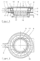
- Figure 1 shows a vertical section through a mixing head according to the invention.
- FIG. 2 shows a top view of the mixing head according to FIG. 1.
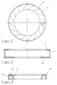
- Figure 3 shows a plan view of a nozzle ring of the mixing head.
- Figure 4 shows a vertical section through the base body of the mixing head.
- Figure 5 shows a vertical section through a simplified intermediate ring of the Mixing head.
- Figure 6 shows a top view of another nozzle ring.
- FIG. 7 shows a vertical section through the nozzle ring according to FIG. 6.
- FIG. 8 shows a plan view of a further nozzle ring.
- Figure 9 shows a vertical section through another nozzle ring.
- FIG. 10 shows a top view of the nozzle ring according to FIG. 9.
- Figure 11 shows a vertical section through a further nozzle ring.
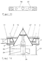
- Figure 12 shows a vertical section through a further mixing head.
- Figure 1 shows an annular mixing head 1, which is only indicated conical lower part 2 of a not shown Mixing container is attached.
- the mixing container belongs to the state of the art. He has essentially the obvious from the aforementioned DE-AS 14 32 0 30 Form and therefore needs no further description.
- the mixing head 1 has an annular pressure chamber 3 with a rectangular cross section, which in the installed state via a connection 4 or more evenly over such connections distributed around the circumference in connection with a compressed air source stands. It is enclosed by walls in the manner of a torus, by one Bottom ring 5, an outer wall 6, a cover ring 7 and a wall close to the axis 8.
- the outer wall 6 consists of a cylindrical sheet metal jacket, the lower Edge with the outer edge of the bottom ring 5 and its upper edge with the outer edge of the cover ring 7 is welded. It forms together with the Bottom ring 5 and the cover ring 7 shown separately in Figure 4 Basic body.
- the wall 8 near the axis is constructed in layers.
- a flat nozzle ring 9 On an inner zone of the Bottom ring 5 is a flat nozzle ring 9. It encloses a circular one Opening which is congruent with the opening of the bottom ring 5.
- the Nozzle ring 9 has flat end faces.
- An intermediate ring 10 sits on the nozzle ring 9, whose profile is similar to an inverted U. Its wall shell 11 close to the axis is conical. The cone angle coincides with the cone angle of the lower part 2.
- the Wall shell 11 of the intermediate ring 10 open at the bottom lies with its lower edge on the edge of the nozzle ring 9 near the axis.
- the outer, the pressure chamber 3 Adjacent wall shell 12 of the intermediate ring 10 is cylindrical and has the same outer diameter as the nozzle ring 9.
- the outer edge of the bridge part 13 is on the inner diameter of the cover ring 7 adapted so that the intermediate ring 10 in the cover ring 7 by positive locking is centered.
- annular seal 15 made of elastic Material.
- the cover ring 7 is connected to the flange 14 by screws.
- the Nozzle ring 9 and the intermediate ring 10 are between the base plate 5 and the Flange 14 clamped. You will be alone by the tension and the Form-fit held together and fixed.
- FIG. 5 shows a further intermediate ring 10 in which the wall shell close to the axis 11, the wall shell 12 remote from the axis and the bridge part 13 manufactured separately and are welded together.
- a flat slide 16 is attached, with which the Open the opening of the bottom ring 5 or block it.
- the nozzle ring 9 illustrated separately in FIG. 3 is made of strong sheet metal manufactured. Its thickness is approximately 1: 2 to the height of the pressure chamber 3 to 1: 5. On its underside, which lies tightly on the bottom ring 5, it is with provided several evenly distributed milled grooves 17, which differ from the outer envelope surface of the nozzle ring 9 up to its near-axis envelope surface extend.
- the grooves 17 are in the installed state through the end face of the Bottom ring 5, on which the nozzle ring 9 rests, covered and form on this Way closed channels all around. They have one along their entire length constant rectangular cross-section. They run straight and close with an associated radial line - as illustrated in Figure 3 - a pointed Angle ⁇ on.
- the direction of the grooves 17 therefore has a radial one Component also a tangential component that is the same size for all grooves 17 and has the same direction of rotation with respect to the axis of the mixing head 1.
- the nozzle ring 9 can also consist of a flat, smooth sheet metal ring and several separately manufactured sector-like disks exist in the manner on the Sheet metal ring are attached so that there is a groove between every two adjacent disks 17 is located. If the grooves are very close together, the sector-like disks should be so narrow that they tend to be ribs or spokes too are designated.
- the nozzle ring 9a illustrated in FIG. 6 and FIG. 7 has in comparison to that The embodiment described above has a smaller number of grooves 17a. They are wider than the grooves 17.
- the bottom of the groove is near the mouth, that means beveled near the inner envelope surface of the nozzle ring 9a, so that the cross section of the groove 17a near the mouth towards the Mouth widened like a wedge.
- Tube 18 clamped the actual in this embodiment Form nozzle channels.
- the tube 18 is cylindrical on the outside and has the inside typical shape of a Laval nozzle. From the inflow opening near the Envelope surface of the nozzle ring 9b remote from the axis is up to a constriction which is approximately at a fifth to a third of the length, the clear cross section narrows, so that the inflow area is reminiscent of a trumpet.
- the cone angle is 10 ° to 14 °.
- the Contour of the rotationally symmetrical inner surface is by dashed lines 19 illustrated.
- the axes of the tubes 18 close, similar to the grooves 17 in Figure 3- an acute angle with associated radial lines.
- Figure 9 and Figure 10 illustrate a nozzle ring 9c especially for Mixing heads that are used when mixing abrasive goods.
- He is on the Provide underside with grooves 20, the arrangement of which is approximately the same as in FIG Figure 6 corresponds to the illustrated arrangement of the grooves 17a.
- the cross section of the Groove 20 is tunnel-shaped.
- a tube 21 is clamped in each groove 20.
- the too Gussets remaining on both sides under the tube 21 are preferred open. They form additional channels for air flows, which are used to whirl up the contribute to ground-level mix.
- the gusset can of course also through Deposits or fillers must be sealed. It is also possible to gusset too avoid by matching the cross section of the tube 21 to the cross section of the Adjust groove 20.
- such a tube 21 is of simplicity and For the sake of clarity, only one groove 20 has been drawn.
- the Tube 21 has a straight, circular cylindrical section which sits in the groove 20, and a curved mouth part, which from the near-axis envelope surface of the Nozzle ring 9c protrudes. This ensures that the blowing direction of the Axial direction of the cylindrical section is angled. In the position according to Figure 9 and Figure 10 has the blowing direction an upward component.
- By rotating the tube 21 about the axis of the cylindrical portion also achieve a tangential component. With optimal setting minimizes wear on the container wall when mixing abrasive goods become.
- the tube 21 can be easily replaced when the Muzzle shows wear.
- the grooves 20 can also be arranged radially.
- the indispensable tangential component of the blowing direction can be determined only by the reach curved mouth portion of the tube 21, which is the actual Nozzle channel forms.
- FIG. 11 there is a nozzle ring 9d with bores 22 provided, which is between the distal and near-axis envelope surface of the Extend nozzle ring 9d.
- this corresponds to Arrangement of the bores 22 essentially the arrangement of the grooves that are made Figure 10 can be seen.
- the holes are oblique to a horizontal plane arranged so that it from the envelope surface remote from the axis towards the axis Slightly increase envelope surface.
- Suitable tubes are, for example, those shown in FIG. 8 Tube 18 or tube 21 according to Figures 9 and 10. In the latter Trap the required tangential component of the blowing direction itself adjust when the holes - different from Figure 12 - are radially aligned are.
- the mixing head according to the invention has compared to comparable mixing heads that belong to the prior art, not only the advantage that it is very simple to manufacture and is therefore much cheaper.
- Another advantage is that it can be replaced by replacing the nozzle ring can be easily adapted to different mixes.
- the grooves or bores can be much denser on the circumference are arranged as the nozzles of comparable mixing heads. This allows the required volume flow can be achieved at much lower pressure. This will at least with small mixers or with mixers that are used for mixing are determined by very fine-grained, powdery material, which so far the compressor required to generate the compressed air can be dispensed with. It is enough that Connect the air reservoir to a compressed air line.
- the fear that the blowing direction is horizontal in some exemplary embodiments can be negative compared to the well-known, upward-blowing mixing heads Has an impact on the function or the mixing result numerous attempts proved to be unfounded.
- the mixing head according to FIG. 12 also has an important advantage, which is the Invention is due. Since the mouth openings directly on the bottom ring 5 are arranged, a locking cone can be used, which in the closed position engages the lower inner edge of the bottom ring 5. The remaining little gusset between the closing cone 27 and the bottom ring 5 is swept free with every pressure surge. The Closing body 27 can easily be removed from below in the event of a blockage become.
Landscapes
- Chemical & Material Sciences (AREA)
- Chemical Kinetics & Catalysis (AREA)
- Engineering & Computer Science (AREA)
- Mechanical Engineering (AREA)
- Processing And Handling Of Plastics And Other Materials For Molding In General (AREA)
- Transition And Organic Metals Composition Catalysts For Addition Polymerization (AREA)
- Coating Apparatus (AREA)
Abstract
Description
Claims (17)
- Mischkopf für einen pneumatischen Mischerdadurch gekennzeichnet,mit einer ringförmigen, nach Art eines Torus von Wänden umschlossenen, an eine Druckluftquelle anschließbaren Druckkammerund mit mehreren in regelmäßigen Winkelabständen angeordneten, von der Druckkammer ausgehenden, die achsnahe Wand durchdringenden Düsenkanälen, die zumindest im Bereich ihrer Mündung eine tangentiale, bei allen Düsenkanälen in Bezug auf die Achse im gleichen Drehsinn gerichtete Richtungskomponente haben,daß in der achsnahen Wand (8) der Druckkammer (3) ein getrennt hergestellter Düsenring (9, 9a,) schichtartig zwischen zwei anderen ringförmigen Bauteilen (5, 10) sitztund daß eine Stirnfläche des Düsenringes (9, 9a) mit Nuten (17, 17a) versehen ist, welche -abgedeckt durch eine an dieser Stirnfläche anliegende Gegenfläche eines anderen Bauteils (5)- die Düsenkanäle bilden.
- Mischkopf für einen pneumatischen Mischerdadurch gekennzeichnet,mit einer ringförmigen, nach Art eines Torus von Wänden umschlossenen, an eine Druckluftquelle anschließbaren Druckkammerund mit mehreren in regelmäßigen Winkelabständen angeordneten, von der Druckkammer ausgehenden, die achsnahe Wand durchdringenden Düsenkanälen, die zumindest im Bereich ihrer Mündung eine tangentiale, bei allen Düsenkanälen in Bezug auf die Achse im gleichen Drehsinn gerichtete Richtungskomponente haben,daß in der achsnahen Wand (8) der Druckkammer (3) ein getrennt hergestellter Düsenring (9d) schichtartig zwischen zwei anderen ringförmigen Bauteilen (5, 10) sitztund daß der Düsenring (9d) mit Bohrungen (22) versehen ist, welche sich zwischen der achsfernen und der achsnahen Hüllfläche erstreckenund daß die Bohrungen (22) die Düsenkanäle bilden.
- Mischkopf für einen pneumatischen Mischerdadurch gekennzeichnet,mit einer ringförmigen, nach Art eines Torus von Wänden umschlossenen, an eine Druckluftquelle anschließbaren Druckkammerund mit mehreren in regelmäßigen Winkelabständen angeordneten, von der Druckkammer ausgehenden, die achsnahe Wand durchdringenden Düsenkanälen, die zumindest im Bereich ihrer Mündung eine tangentiale, bei allen Düsenkanälen in Bezug auf die Achse im gleichen Drehsinn gerichtete Richtungskomponente haben,daß in der achsnahen Wand (8) der Druckkammer (3) ein getrennt hergestellter Düsenring (9c) schichtartig zwischen zwei anderen ringförmigen Bauteilen (5, 10) sitztund daß in Nuten (20), die in eine Stirnfläche des Düsenringes (9c) eingearbeitet sind, Röhrchen (21) sitzen, welche die Düsenkanäle bilden.
- Mischkopf für einen pneumatischen Mischerdadurch gekennzeichnet,mit einer ringförmigen, nach Art eines Torus von Wänden umschlossenen, an eine Druckluftquelle anschließbaren Druckkammerund mit mehreren in regelmäßigen Winkelabständen angeordneten, von der Druckkammer ausgehenden, die achsnahe Wand durchdringenden Düsenkanälen, die zumindest im Bereich ihrer Mündung eine tangentiale, bei allen Düsenkanälen in Bezug auf die Achse im gleichen Drehsinn gerichtete Richtungskomponente haben,daß in der achsnahen Wand (8) der Druckkammer (3) ein getrennt hergestellter Düsenring (9b) schichtartig zwischen zwei anderen ringförmigen Bauteilen (5, 10) sitztdaß in Bohrungen, welche sich zwischen der achsfernen und der achsnahen Hüllfläche des Düsenringes (9b) erstrecken, Röhrchen (18) sitzen, welche die Düsenkanäle bilden.
- Mischkopf nach Anspruch 1 oder 3,
dadurch gekennzeichnet,
daß der Düsenring (9, 9a, 9c) einstückig aus Stahlblech hergestellt ist und daß eine Stirnfläche mit eingefrästen Nuten (17, 17a, 20) versehen ist. - Mischkopf nach Anspruch 1 oder 3,
dadurch gekennzeichnet,
daß der Düsenring (9, 9a) aus Stahlblech hergestellt ist, daß auf einer Stirnfläche mehrere sektorartige Scheiben oder Rippen befestigt sind und daß sich zwischen je zwei benachbarten Scheiben oder Rippen eine Nut (17, 17a) befindet. - Mischkopf nach Anspruch 1,
dadurch gekennzeichnet,
daß die Nut (17a) durch eine Abschrägung des Nutengrundes zumindest in der Nähe der Mündung keilartig erweitert ist. - Mischkopf nach Anspruch 3,
dadurch gekennzeichnet,
daß die Nut (20) einen tunnelförmigen Querschnitt hat. - Mischkopf nach Anspruch 2 oder 4,
dadurch gekennzeichnet,
daß die Bohrung (22) von der achsfernen Hüllfläche des Düsenringes (9d) in Richtung auf die achsnahe Hüllfläche ansteigt. - Mischkopf nach Anspruch 3 oder 4,
dadurch gekennzeichnet,
daß die Innenfläche (19) des Röhrchens (18) nach Art einer Lavaldüse geformt ist. - Mischkopf nach Anspruch 3 oder 4,
dadurch gekennzeichnet,
daß das Röhrchen (21) einen gekrümmten Mündungsteil aufweist, der aus der achsnahen Hüllfläche des Düsenringes (9c) herausragt, und daß die Blasrichtung an der Mündung eine tangentiale und/oder eine nach oben gerichtete Komponente aufweist. - Mischkopf nach einem der Ansprüche 1 bis 11,
dadurch gekennzeichnet,
daß ein zylindrischer Blechmantel (6), dessen unterer Rand mit dem Bodenring (5) und dessen oberer Rand mit einem Abdeckring (7) verschweißt ist, die Außenwand der Druckkammer (3) bildet. - Mischkopf nach Anspruch 12,
dadurch gekennzeichnet,
daß die Höhe des Blechmantels (6) größer ist als die Dicke des Düsenringes (9, 9a, 9b, 9c, 9d) und daß auf dem Düsenring ein Zwischenring (10) sitzt, der den oberen Teil der achsnahen Wand (8) der Druckkammer (3) bildet. - Mischkopf nach Anspruch 13,
dadurch gekennzeichnet,
daß der Zwischenring (10) in der Öffnung des Abdeckringes (7) formschlüssig zentriert ist und durch formschlüssigen Eingriff in eine Ausnehmung des Düsenringes (9, 9a, 9b, 9c, 9d) diesen zentriert. - Mischkopf nach Anspruch 13 oder 14,
dadurch gekennzeichnet,
daß der Düsenring (9, 9a, 9b, 9c, 9d) und der Zwischenring (10) zwischen dem Bodenring (5) und einem Flansch (14) eingespannt sind, an dessen Unterseite der Abdeckring (7) angeschraubt ist. - Mischkopf nach einem der Ansprüche 1 bis 15,
gekennzeichnet durch einen an der Unterseite des Bodenringes (5) angebrachten Flachschieber (16). - Mischkopf nach einem der Ansprüche 1 bis 15,
dadurch gekennzeichnet,
daß an der Unterseite des Bodenringes (5) eine Tragvorrichtung (23, 24) eines heb- und senkbaren Schließkegels (27) angebracht ist, der in der angehobenen Stellung am unteren Innenrand des Bodenringes (5) dicht anliegt.
Applications Claiming Priority (2)
| Application Number | Priority Date | Filing Date | Title |
|---|---|---|---|
| DE10007718 | 2000-02-19 | ||
| DE10007718A DE10007718C1 (de) | 2000-02-19 | 2000-02-19 | Mischkopf für einen pneumatischen Mischer |
Publications (3)
| Publication Number | Publication Date |
|---|---|
| EP1125628A2 true EP1125628A2 (de) | 2001-08-22 |
| EP1125628A3 EP1125628A3 (de) | 2003-07-30 |
| EP1125628B1 EP1125628B1 (de) | 2006-06-21 |
Family
ID=7631623
Family Applications (1)
| Application Number | Title | Priority Date | Filing Date |
|---|---|---|---|
| EP01102298A Expired - Lifetime EP1125628B1 (de) | 2000-02-19 | 2001-02-01 | Pneumatischer Mischer |
Country Status (3)
| Country | Link |
|---|---|
| EP (1) | EP1125628B1 (de) |
| AT (1) | ATE330701T1 (de) |
| DE (2) | DE10007718C1 (de) |
Cited By (3)
| Publication number | Priority date | Publication date | Assignee | Title |
|---|---|---|---|---|
| WO2002055743A3 (de) * | 2001-01-12 | 2002-11-07 | Babcock Bsh Gmbh | Anlage zur herstellung von puderzucker aus kristallzucker oder invertiertem zucker |
| WO2008017875A1 (en) * | 2006-08-11 | 2008-02-14 | Maelgwyn Mineral Services Limited | A device for dispersing a gas into a liquid |
| RU214953U1 (ru) * | 2022-05-27 | 2022-11-22 | Федеральное государственное автономное образовательное учреждение высшего образования "Сибирский федеральный университет" | Активатор жидких сред |
Families Citing this family (2)
| Publication number | Priority date | Publication date | Assignee | Title |
|---|---|---|---|---|
| DE102012208717A1 (de) | 2012-05-24 | 2013-11-28 | Coperion Gmbh | Behandlungsvorrichtung sowie Behandlungsanlage für Schüttgut |
| CN111672367A (zh) * | 2020-07-22 | 2020-09-18 | 湖南广盛源医药科技有限公司 | 一种用于消毒液生产的分散剪切装置及其使用方法 |
Family Cites Families (11)
| Publication number | Priority date | Publication date | Assignee | Title |
|---|---|---|---|---|
| DE1152877B (de) * | 1960-03-19 | 1963-08-14 | Oberhessische Muehlenbauanstal | Vorrichtung zum Mischen und Behandeln von pulverfoermigen oder koernigen Stoffen |
| DE1172934B (de) * | 1962-04-12 | 1964-06-25 | Gustav Gruen | Pneumatischer Mischer fuer in Pulverform oder als Granulat vorliegende Mischstoffe |
| LU41580A1 (de) * | 1962-04-19 | 1962-06-19 | ||
| DE1432030A1 (de) * | 1963-06-08 | 1969-06-19 | Gruen Geb Kg Maschf | Verfahren und Vorrichtung zum Mischen von in Pulverform oder als Granulat vorliegenden Stoffen |
| DE2121636C3 (de) * | 1971-05-03 | 1974-07-04 | Buettner-Schilde-Haas Ag, 4150 Krefeld | Pneumatischer Mischer für Pulver oder Granulate |
| DE2522088C2 (de) * | 1975-05-17 | 1986-02-06 | Dynamic Air Inc., St. Paul, Minn. | Vorrichtung zur Mischung von Granulaten durch Einblasen eines gasförmigen Mediums, insbesondere von Druckluft in einen Behälter |
| DE2850271C3 (de) * | 1978-11-20 | 1981-10-01 | Degussa Ag, 6000 Frankfurt | Vorrichtung zur intensiven Mischung von Flüssigkeiten |
| IT1150650B (it) * | 1982-03-10 | 1986-12-17 | Montedison Spa | Reattore a letto fluido |
| US5004484A (en) * | 1988-08-31 | 1991-04-02 | Barrett, Haentjens & Co. | Air stripping of liquids using high intensity turbulent mixer |
| US5131757A (en) * | 1991-03-07 | 1992-07-21 | Hazleton Environmental Products Inc. | Mixing apparatus and system |
| DE19650559C1 (de) * | 1996-12-05 | 1998-03-26 | Mtu Friedrichshafen Gmbh | Anschlußelement zum Einleiten von Brennstoff und einem zweiten Fluid in ein Einspritzventil |
-
2000
- 2000-02-19 DE DE10007718A patent/DE10007718C1/de not_active Expired - Fee Related
-
2001
- 2001-02-01 AT AT01102298T patent/ATE330701T1/de not_active IP Right Cessation
- 2001-02-01 DE DE50110195T patent/DE50110195D1/de not_active Expired - Lifetime
- 2001-02-01 EP EP01102298A patent/EP1125628B1/de not_active Expired - Lifetime
Cited By (4)
| Publication number | Priority date | Publication date | Assignee | Title |
|---|---|---|---|---|
| WO2002055743A3 (de) * | 2001-01-12 | 2002-11-07 | Babcock Bsh Gmbh | Anlage zur herstellung von puderzucker aus kristallzucker oder invertiertem zucker |
| WO2008017875A1 (en) * | 2006-08-11 | 2008-02-14 | Maelgwyn Mineral Services Limited | A device for dispersing a gas into a liquid |
| EA014013B1 (ru) * | 2006-08-11 | 2010-08-30 | Мэилгвин Минерал Сервисиз Лимитед | Устройство для диспергирования газа в жидкости |
| RU214953U1 (ru) * | 2022-05-27 | 2022-11-22 | Федеральное государственное автономное образовательное учреждение высшего образования "Сибирский федеральный университет" | Активатор жидких сред |
Also Published As
| Publication number | Publication date |
|---|---|
| EP1125628A3 (de) | 2003-07-30 |
| DE50110195D1 (de) | 2006-08-03 |
| EP1125628B1 (de) | 2006-06-21 |
| DE10007718C1 (de) | 2001-07-05 |
| ATE330701T1 (de) | 2006-07-15 |
Similar Documents
| Publication | Publication Date | Title |
|---|---|---|
| EP1395358B1 (de) | Vorrichtung zum behandeln von partikelförmigem gut | |
| EP1232003A2 (de) | Vorrichtung zum beschichten von partikeln | |
| WO1984001113A1 (fr) | Appareillage de lit fluidise | |
| EP0544125A2 (de) | Luftdurchlass | |
| DE2425727B2 (de) | Vorrichtung zum Behandeln von Stoffen, insbesondere zum Mischen von körnigen, pulverförmigen, pastenförmigen und/oder flüssigen Massen | |
| DE102008006558A1 (de) | Inertgasschleuse zur Befüllung eines Behälters mit Schüttgut | |
| DE69018288T2 (de) | Vorrichtung zum Mischen und Austragen von körnigem Feststoff aus einem Behälter. | |
| DE4108048C2 (de) | ||
| DE1223237B (de) | Strahlmuehle mit flachzylindrischer Mahlkammer | |
| DE10007718C1 (de) | Mischkopf für einen pneumatischen Mischer | |
| DE3107959C2 (de) | ||
| DE615771C (de) | Vorrichtung zum Mischen von mehlfoermigem oder staubartigem Gut | |
| EP0170080A1 (de) | Vorrichtung zum Verteilen von Schüttgut in einem Behälter | |
| DE3640282C1 (de) | Vorrichtung und Verfahren zur Steuerung eines Schleusvorganges fuer ein Haufwerk von Schuettgutpartikeln | |
| DE3125110C2 (de) | Schüttgutbunker-Austragvorrichtung | |
| DE1297447B (de) | Mischvorrichtung fuer pulverfoermige, faserige oder koernige Schuettgueter | |
| DE3334749C2 (de) | ||
| EP1017859B1 (de) | Verfahren zur erzeugung von eisenschwamm | |
| DE3829263A1 (de) | Vorrichtung zum verteilen eines stroemenden fluessigkeits-gas-gemisches in mehrere teilstroeme | |
| CH369346A (de) | Verfahren und Vorrichtung zum Mischen von pulverförmigen oder feinkörnigen Stoffen miteinander oder mit einer Flüssigkeit | |
| DE4410568C1 (de) | Dosiervorrichtung | |
| WO2009037159A1 (de) | Schwingmühle | |
| DE202019104874U1 (de) | Mischmaschine | |
| DE1081906B (de) | Verfahren und Vorrichtung zum Betrieb eines Hochofens | |
| DE2111760A1 (de) | Vorrichtung zum Entladen einer Bodenfraktion in einem Wirbelabscheider |
Legal Events
| Date | Code | Title | Description |
|---|---|---|---|
| PUAI | Public reference made under article 153(3) epc to a published international application that has entered the european phase |
Free format text: ORIGINAL CODE: 0009012 |
|
| AK | Designated contracting states |
Kind code of ref document: A2 Designated state(s): AT BE CH CY DE DK ES FI FR GB GR IE IT LI LU MC NL PT SE TR |
|
| AX | Request for extension of the european patent |
Free format text: AL;LT;LV;MK;RO;SI |
|
| RAP1 | Party data changed (applicant data changed or rights of an application transferred) |
Owner name: GRENZEBACH BSH GMBH |
|
| PUAL | Search report despatched |
Free format text: ORIGINAL CODE: 0009013 |
|
| AK | Designated contracting states |
Designated state(s): AT BE CH CY DE DK ES FI FR GB GR IE IT LI LU MC NL PT SE TR |
|
| AX | Request for extension of the european patent |
Extension state: AL LT LV MK RO SI |
|
| 17P | Request for examination filed |
Effective date: 20040130 |
|
| AKX | Designation fees paid |
Designated state(s): AT BE CH CY DE DK ES FI FR GB GR IE IT LI LU MC NL PT SE TR |
|
| 17Q | First examination report despatched |
Effective date: 20040706 |
|
| GRAP | Despatch of communication of intention to grant a patent |
Free format text: ORIGINAL CODE: EPIDOSNIGR1 |
|
| RTI1 | Title (correction) |
Free format text: PNEUMATIC MIXER |
|
| GRAS | Grant fee paid |
Free format text: ORIGINAL CODE: EPIDOSNIGR3 |
|
| GRAA | (expected) grant |
Free format text: ORIGINAL CODE: 0009210 |
|
| AK | Designated contracting states |
Kind code of ref document: B1 Designated state(s): AT BE CH CY DE DK ES FI FR GB GR IE IT LI LU MC NL PT SE TR |
|
| PG25 | Lapsed in a contracting state [announced via postgrant information from national office to epo] |
Ref country code: IT Free format text: LAPSE BECAUSE OF FAILURE TO SUBMIT A TRANSLATION OF THE DESCRIPTION OR TO PAY THE FEE WITHIN THE PRESCRIBED TIME-LIMIT;WARNING: LAPSES OF ITALIAN PATENTS WITH EFFECTIVE DATE BEFORE 2007 MAY HAVE OCCURRED AT ANY TIME BEFORE 2007. THE CORRECT EFFECTIVE DATE MAY BE DIFFERENT FROM THE ONE RECORDED. Effective date: 20060621 Ref country code: IE Free format text: LAPSE BECAUSE OF FAILURE TO SUBMIT A TRANSLATION OF THE DESCRIPTION OR TO PAY THE FEE WITHIN THE PRESCRIBED TIME-LIMIT Effective date: 20060621 Ref country code: NL Free format text: LAPSE BECAUSE OF FAILURE TO SUBMIT A TRANSLATION OF THE DESCRIPTION OR TO PAY THE FEE WITHIN THE PRESCRIBED TIME-LIMIT Effective date: 20060621 Ref country code: FI Free format text: LAPSE BECAUSE OF FAILURE TO SUBMIT A TRANSLATION OF THE DESCRIPTION OR TO PAY THE FEE WITHIN THE PRESCRIBED TIME-LIMIT Effective date: 20060621 |
|
| REG | Reference to a national code |
Ref country code: GB Ref legal event code: FG4D Free format text: NOT ENGLISH |
|
| REG | Reference to a national code |
Ref country code: CH Ref legal event code: EP |
|
| REG | Reference to a national code |
Ref country code: IE Ref legal event code: FG4D Free format text: LANGUAGE OF EP DOCUMENT: GERMAN |
|
| REF | Corresponds to: |
Ref document number: 50110195 Country of ref document: DE Date of ref document: 20060803 Kind code of ref document: P |
|
| PG25 | Lapsed in a contracting state [announced via postgrant information from national office to epo] |
Ref country code: DK Free format text: LAPSE BECAUSE OF FAILURE TO SUBMIT A TRANSLATION OF THE DESCRIPTION OR TO PAY THE FEE WITHIN THE PRESCRIBED TIME-LIMIT Effective date: 20060921 Ref country code: SE Free format text: LAPSE BECAUSE OF FAILURE TO SUBMIT A TRANSLATION OF THE DESCRIPTION OR TO PAY THE FEE WITHIN THE PRESCRIBED TIME-LIMIT Effective date: 20060921 |
|
| PG25 | Lapsed in a contracting state [announced via postgrant information from national office to epo] |
Ref country code: ES Free format text: LAPSE BECAUSE OF FAILURE TO SUBMIT A TRANSLATION OF THE DESCRIPTION OR TO PAY THE FEE WITHIN THE PRESCRIBED TIME-LIMIT Effective date: 20061002 |
|
| GBT | Gb: translation of ep patent filed (gb section 77(6)(a)/1977) |
Effective date: 20060924 |
|
| PG25 | Lapsed in a contracting state [announced via postgrant information from national office to epo] |
Ref country code: PT Free format text: LAPSE BECAUSE OF FAILURE TO SUBMIT A TRANSLATION OF THE DESCRIPTION OR TO PAY THE FEE WITHIN THE PRESCRIBED TIME-LIMIT Effective date: 20061121 |
|
| NLV1 | Nl: lapsed or annulled due to failure to fulfill the requirements of art. 29p and 29m of the patents act | ||
| REG | Reference to a national code |
Ref country code: IE Ref legal event code: FD4D |
|
| PG25 | Lapsed in a contracting state [announced via postgrant information from national office to epo] |
Ref country code: LI Free format text: LAPSE BECAUSE OF NON-PAYMENT OF DUE FEES Effective date: 20070228 Ref country code: MC Free format text: LAPSE BECAUSE OF NON-PAYMENT OF DUE FEES Effective date: 20070228 Ref country code: CH Free format text: LAPSE BECAUSE OF NON-PAYMENT OF DUE FEES Effective date: 20070228 |
|
| PLBE | No opposition filed within time limit |
Free format text: ORIGINAL CODE: 0009261 |
|
| STAA | Information on the status of an ep patent application or granted ep patent |
Free format text: STATUS: NO OPPOSITION FILED WITHIN TIME LIMIT |
|
| EN | Fr: translation not filed | ||
| 26N | No opposition filed |
Effective date: 20070322 |
|
| REG | Reference to a national code |
Ref country code: CH Ref legal event code: PL |
|
| BERE | Be: lapsed |
Owner name: GRENZEBACH BSH G.M.B.H. Effective date: 20070228 |
|
| PG25 | Lapsed in a contracting state [announced via postgrant information from national office to epo] |
Ref country code: BE Free format text: LAPSE BECAUSE OF NON-PAYMENT OF DUE FEES Effective date: 20070228 |
|
| PG25 | Lapsed in a contracting state [announced via postgrant information from national office to epo] |
Ref country code: GR Free format text: LAPSE BECAUSE OF FAILURE TO SUBMIT A TRANSLATION OF THE DESCRIPTION OR TO PAY THE FEE WITHIN THE PRESCRIBED TIME-LIMIT Effective date: 20060922 Ref country code: FR Free format text: LAPSE BECAUSE OF FAILURE TO SUBMIT A TRANSLATION OF THE DESCRIPTION OR TO PAY THE FEE WITHIN THE PRESCRIBED TIME-LIMIT Effective date: 20070309 |
|
| PG25 | Lapsed in a contracting state [announced via postgrant information from national office to epo] |
Ref country code: AT Free format text: LAPSE BECAUSE OF NON-PAYMENT OF DUE FEES Effective date: 20070201 |
|
| PG25 | Lapsed in a contracting state [announced via postgrant information from national office to epo] |
Ref country code: FR Free format text: LAPSE BECAUSE OF FAILURE TO SUBMIT A TRANSLATION OF THE DESCRIPTION OR TO PAY THE FEE WITHIN THE PRESCRIBED TIME-LIMIT Effective date: 20060621 |
|
| PG25 | Lapsed in a contracting state [announced via postgrant information from national office to epo] |
Ref country code: LU Free format text: LAPSE BECAUSE OF NON-PAYMENT OF DUE FEES Effective date: 20070201 Ref country code: CY Free format text: LAPSE BECAUSE OF FAILURE TO SUBMIT A TRANSLATION OF THE DESCRIPTION OR TO PAY THE FEE WITHIN THE PRESCRIBED TIME-LIMIT Effective date: 20060621 |
|
| PG25 | Lapsed in a contracting state [announced via postgrant information from national office to epo] |
Ref country code: TR Free format text: LAPSE BECAUSE OF FAILURE TO SUBMIT A TRANSLATION OF THE DESCRIPTION OR TO PAY THE FEE WITHIN THE PRESCRIBED TIME-LIMIT Effective date: 20060621 |
|
| PGFP | Annual fee paid to national office [announced via postgrant information from national office to epo] |
Ref country code: GB Payment date: 20110221 Year of fee payment: 11 Ref country code: DE Payment date: 20110419 Year of fee payment: 11 |
|
| GBPC | Gb: european patent ceased through non-payment of renewal fee |
Effective date: 20120201 |
|
| REG | Reference to a national code |
Ref country code: DE Ref legal event code: R119 Ref document number: 50110195 Country of ref document: DE Effective date: 20120901 |
|
| PG25 | Lapsed in a contracting state [announced via postgrant information from national office to epo] |
Ref country code: GB Free format text: LAPSE BECAUSE OF NON-PAYMENT OF DUE FEES Effective date: 20120201 |
|
| PG25 | Lapsed in a contracting state [announced via postgrant information from national office to epo] |
Ref country code: DE Free format text: LAPSE BECAUSE OF NON-PAYMENT OF DUE FEES Effective date: 20120901 |