EP1125645A2 - Séparateur pour la séparation à sec de poudres - Google Patents
Séparateur pour la séparation à sec de poudres Download PDFInfo
- Publication number
- EP1125645A2 EP1125645A2 EP01400419A EP01400419A EP1125645A2 EP 1125645 A2 EP1125645 A2 EP 1125645A2 EP 01400419 A EP01400419 A EP 01400419A EP 01400419 A EP01400419 A EP 01400419A EP 1125645 A2 EP1125645 A2 EP 1125645A2
- Authority
- EP
- European Patent Office
- Prior art keywords
- cavity
- powder
- disk
- feeding
- cavity surface
- Prior art date
- Legal status (The legal status is an assumption and is not a legal conclusion. Google has not performed a legal analysis and makes no representation as to the accuracy of the status listed.)
- Withdrawn
Links
Images


Classifications
-
- B—PERFORMING OPERATIONS; TRANSPORTING
- B07—SEPARATING SOLIDS FROM SOLIDS; SORTING
- B07B—SEPARATING SOLIDS FROM SOLIDS BY SIEVING, SCREENING, SIFTING OR BY USING GAS CURRENTS; SEPARATING BY OTHER DRY METHODS APPLICABLE TO BULK MATERIAL, e.g. LOOSE ARTICLES FIT TO BE HANDLED LIKE BULK MATERIAL
- B07B13/00—Grading or sorting solid materials by dry methods, not otherwise provided for; Sorting articles otherwise than by indirectly controlled devices
- B07B13/10—Grading or sorting solid materials by dry methods, not otherwise provided for; Sorting articles otherwise than by indirectly controlled devices using momentum effects
- B07B13/11—Grading or sorting solid materials by dry methods, not otherwise provided for; Sorting articles otherwise than by indirectly controlled devices using momentum effects involving travel of particles over surfaces which separate by centrifugal force or by relative friction between particles and such surfaces, e.g. helical sorters
-
- B—PERFORMING OPERATIONS; TRANSPORTING
- B07—SEPARATING SOLIDS FROM SOLIDS; SORTING
- B07B—SEPARATING SOLIDS FROM SOLIDS BY SIEVING, SCREENING, SIFTING OR BY USING GAS CURRENTS; SEPARATING BY OTHER DRY METHODS APPLICABLE TO BULK MATERIAL, e.g. LOOSE ARTICLES FIT TO BE HANDLED LIKE BULK MATERIAL
- B07B13/00—Grading or sorting solid materials by dry methods, not otherwise provided for; Sorting articles otherwise than by indirectly controlled devices
-
- Y—GENERAL TAGGING OF NEW TECHNOLOGICAL DEVELOPMENTS; GENERAL TAGGING OF CROSS-SECTIONAL TECHNOLOGIES SPANNING OVER SEVERAL SECTIONS OF THE IPC; TECHNICAL SUBJECTS COVERED BY FORMER USPC CROSS-REFERENCE ART COLLECTIONS [XRACs] AND DIGESTS
- Y10—TECHNICAL SUBJECTS COVERED BY FORMER USPC
- Y10S—TECHNICAL SUBJECTS COVERED BY FORMER USPC CROSS-REFERENCE ART COLLECTIONS [XRACs] AND DIGESTS
- Y10S209/00—Classifying, separating, and assorting solids
- Y10S209/919—Rotary feed conveyor
Definitions
- the present invention relates to separation of dry powders, more particularly it relates to a centrifugal separator for continuous separation of dry powders.
- air separation separation is realized by air jets, which remove fine particles out of powder flow and transfer them to a hopper, and heavy particles, which are not carried out by an air jet, fall into another hopper.
- U.S. Patent No. 5,934,483 to KOLACZ discloses an apparatus of the forced air vortex type for classification of particulate material into a fine portion and a coarse portion, the apparatus comprises a truncated cone shaped upper section having a separating wheel rotating about a substantially vertical axis, a vertically arranged inlet pipe for supplying a particulate material dispersed in an air flow, a conical feed distributor having a tip end directed downwards and arranged concentrically with the inlet pipe and the separating wheel, and a spiral shaped outlet for removal of classified fine material dispersed in air, and a substantially truncated cone shaped lower section, the upper section of which exhibit a secondary air inlet arranged tangentially to the circumference of the lower housing to supply secondary air in a direction concurrently with the direction of rotation of the separating wheel and a second outlet for classified coarse particulate material.
- U.S. Patent No. 4,869,786 to HANKE discloses a process and an air classifier for the separation of classifying material into coarse material and fine material.
- Known air classifiers suffer from considerable deficiencies with regards to the throughput and the separation efficiency.
- the device provides for the performance of a separate reclassification, which takes place in the same way as the pre-classification, whilst incorporating mechanical centrifugal rejection of coarse material particles, particularly through the impact ledges of a centrifuge basket.
- U.S. Patent No. 3,941,687 to PETERSON discloses a solids separation system designed for pneumatic separation of pieces of scrap particularly metallic scrap, into light and heavy fractions.
- the mixture of pieces of scrap is fed into an enclosed separation vessel wherein they fall by gravity into a horizontally directed stream of air blown into and across the separator vessel, whereby the heaviest pieces fall through the air stream into a heavy solids hopper and the lighter materials are carried downstream by the force of the horizontal air stream into a second hopper.
- a gas outlet port is provided at the top of the vessel thereby imparting an upward velocity vector to the gas. The horizontal velocity of the gas being reduced by expansion, light metal pieces fall out of the influence of the gas stream into the light solids hopper.
- Means are provided for adjusting the air flow path from the first into the second hopper comprising a pivoted angularly disposed baffle plate defining the rear wall of the first hopper, the surface of which plate also serves to direct solids intercepted thereby into the first hopper.
- U.S. Patent No. 3,932,442 to SALMON discloses a process for screening materials as a function of particle size differences by feeding the materials onto one side of a substantially planar screen and vibrating the screen by producing a translational screen oscillation in directions normal to the screen plane and a torsional screen oscillation about an axis normal to the screen plane so that each point of the screen moves in a helical path. Screened material is collected at the other side of the screen and screened retentate is transported by the torsional screen oscillation to an exit port at a location spaced from the axis of torsional oscillation.
- the process is particularly applicable to shipboard or other mobile use, since the spring stiffness provides good structural support under tilt or side acceleration conditions.
- Vibro-gravitational separation consists in a motion of particles of different sizes, densities or shapes under the action of vibration along different paths over an inclined concave. Sometimes numerous holes are made in the concave for the passage of compressed air supply, in order to increase the amplitude of particle jumps. This method has proved to be rather efficient for separating seeds and coarse-grain powders. However, its efficiency for powders with a medium particle size below I 00 pm is rather low.
- a separator proposed in this application operates cyclically.
- the powder is fed to the center of horizontal rotating disk, which spreads it along the entire Internal wall of a rotating cup. Dry powder is separated into two fractions on the internal wall of a rotating cup under the action of friction force and centrifugal force on each particle. Larger particles are allowed to pass over the upper edge of the cup, whereas smaller ones remain on the cup wall. However, to make particles fall down from the cup wall, it is necessary to stop the cup.
- the present invention therefore provides a centrifugal separator for dry separation of powders having a high efficiency and a low power consumption due to its continuous operation.
- the feeding of powder to be separated and the removal of coarse and fine powder fractions after separation take place simultaneously and continuously.
- Powder separation occurs on a wall of a cavity of a rotating body.
- the body rotates around a vertical axis and has a centrally symmetrical cavity open from above and from below.
- the cavity symmetry axis coincides with the body rotation axis, and the cavity surface is a surface of revolution with circular upper and lower edge's of this cavity, the diameter of the upper circumference being greater that the diameter of the lower circumference.
- Powder is fed to a certain zone which is designated a feeding zone and which is positioned adjacent to a lower portion of the cavity surface.
- the length of this zone is designed to be much less (at least by an order of magnitude) than the length of a separation zone, with the length of the separation zone being approximately 1s,
- the length (in meters) of the separation zone is determined by the relationship is ⁇ 1gxV/Vg, where 1g is the distance (in meters) between the lower edge of the feeding zone to the upper edge of the cavity surface along the generatrix of the surface of revolution, V is the linear velocity (in meters/second) of the upper edge of cavity surface, and Vg is the velocity (in meters/second) of the coarse powder fraction motion upwards along the generatrix of the surface of revolution.
- the velocity V depends on the material characteristics of the bowl, such as roughness, diameter, and shape.
- the following data correspond to the following bowl characteristics: the diameter of the upper edge of the bowl is 0.4 meters; the angle of the bowl surface is 40 degrees relative to the vertical bowl axis; and the surface roughness of the bowl surface is 2-3 microns, where 1 micron equals 10 -6 meters.
- the diameter of coarse fraction particles can be designated as di > d, where d is the diameter of particles (in microns) according to which particles are separated into two fractions.
- the discharge zone where a discharge facility or discharge device discharges the powder particles remaining on the cavity surface.
- this device is arranged along the entire generatrix of the surface of revolution.
- Separation proceeds as follows.
- the powder falls on a rotating surface of a cavity having a certain roughness (for example, a roughness of 2-3 microns is adequate for separating fly ash and graphite in a manner depicted in figures 10 and 11) Since the resultant of all the forces acting on powder particles is different for large and small particles, the larger particles move upward and, during the passage of the separation zone from the feeding zone to the discharge zone, pass over the upper edge of the cavity surface and fall into one of hoppers. The smaller particles remain on the cavity surface until they reach the discharge device, which discharges them into a respective hopper.
- a certain roughness for example, a roughness of 2-3 microns is adequate for separating fly ash and graphite in a manner depicted in figures 10 and 11
- a further increase in the facility efficiency can be achieved by arranging several feeding zones and, respectively, separation zones and discharge zones along the cavity surface
- one of the fractions which is obtained in one of separation zones can be fed to another separation zone, which will improve the separation quality.
- powder can be fed to the feeding zone by an appropriately oriented pipe having a nozzle or by utilizing a plurality of rotating disks or rings, or else by a conveyer.
- These various rotating disks or rings can have a rotation axis which either does or does not coincide with the cavity rotation axis. Further, they can be driven by the same drive as the body or have an independent drive, each of which is independently controllable. Additionally, these disks or rings can be located in a plane perpendicular to the cavity rotation axis, or in some other plane. Moreover, they may be located in the same plane or one under another.
- the powder is fed by a pipe to the periphery of the rotating disk or ring and thrown into the feeding zone under the action of the centrifugal force.
- One or more discharge devices may be in the form of a flat or round brush adjoining the rotating cavity surface.
- the brushes can be adjustably fixed or movable in longitudinal or transverse direction, or may be adapted to rotate around their axes.
- the discharge device can comprise one brush or several brushes located at various distances form one another.
- the discharge device can even represent a flexible elastic strip with one of end faces adjoining the cavity surface.
- the discharge device also can represent a pipe with a suction nozzle at the end, with the nozzle being arranged along the generatrix of the surface of revolution, and rarefaction is created in the pipe and in the nozzle. Air flow sucked in by the nozzle tears powder particles off the cavity surface in the discharge zone and directs them into the nozzle and further, by the pipe, into a hopper.
- a system for dry separation of powders into at least two fractions including a powder to be separated and a separator comprising a hollow body rotating around a vertical axis, the cavity of the body being often from above and from below and the surface of the cavity represents a surface of revolution with the central axis coinciding with the rotation axis of the body, the upper edge of the cavity having a greater diameter than the lower edge, a system controlling the rotation of the body, at least one feeder continuously feeding dry powder into a feeding zone adjacent to the cavity surface near its lower edge, the length of the zone being at least an order of magnitude less than the circumference of the cavity surface in its lower portion, at least one discharge device continuously discharging powder from the cavity surface, which represents a prolonged body arranged along the entire length of the generatrix (the generatrix being a generating line for a body of revolution.
- the slope of the generatrix of the surface of revolution with respect to the vertical may be within the limits from approximately 10° to 45°, and the roughness of the cavity surface may be within approximately 0.01d to 0.2d, where d is the diameter of particles, by which the powder is separated into fractions so that particles with diameters d ⁇ d are found in one fraction, and particles with diameters di ⁇ d - in another.
- n pairs of feeder/discharging device may be uniformly arranged over the cavity surface so that the following relationship is valid: L ⁇ n(1f+1s+1u), where L is the circumference length of the lower edge of the cavity surface, 1f is the feeding zone length, Is is the separation zone length, lu is the discharging zone length, the separation zone length being 1s ⁇ 1gxV/Vg, where 1g is the distance between the lower edge of the feeding zone to the upper edge of the cavity surface, V is the linear velocity of the upper edge of cavity surface, Vg is the mean velocity of the rise of coarse powder fraction particles along the generatrix of the surface of revolution.
- the feeder may consist of a rotating disk and a pipe for feeding powder to this disk, the disk being disposed inside the cavity of the rotating body in the plane perpendicular to the rotation axis of the rotating body, and the outlet of the feeding pipe located above the disk on its periphery.
- the disk rotation axis may coincide with cavity rotation axis, and the disk has the same drive as the rotating body.
- the disk rotation axis may coincide with cavity rotation axis, and the disk has an independent drive.
- Two or more outlet or feeding pipes may be uniformly arranged above the surface of the disk near its periphery along the its circumference length.
- the feeder may consist of a rotating flat ring and a pipe for feeding powder to this ring, the ring being disposed inside the cavity of the rotating body in the plane perpendicular to the rotation axis of the cavity, and the rotation axis of the ring coincides with the rotation axis of the cavity, the outlet of the feeding pipe being located above the plane of the ring.
- At least two such flat rings may be located one above another. At least one such flat ring may be located above the flat disk.
- the disk rotation axis may not coincide with the cavity rotation rate, the disk having an independent drive, and there is one outlet of the feeding pipe above its periphery.
- Two or more the disks may be uniformly arranged along the cavity surface.
- the disks may be arranged at various heights with respect to the lower edge of the cavity surface.
- the feeder may consist of a rotating disk and a pipe for feeding powder to this disk, the disk being disposed inside the cavity of the rotating body, and the rotation axis of the disk does not coincide with the rotation axis of the cavity and is not parallel to it, the angle between the rotation plane of the disk and the rotation axis of the cavity being within the interval from approximately 45° to 90°, and the disk has an independent drive, and the-re is one outlet of the feeding pipe over its periphery.
- the feeder may represent a feeding pipe with an outlet fitted with a nozzle feeding powder to the feeding zone.
- Two or more nozzles may be uniformly arranged along the cavity surface.
- the feeder may comprise a feeding pipe and a conveyer arranged in the cavity of the rotating body so that the powder on the conveyer moves along the straight line connecting the rotation axis of the rotating body with the cavity surface, and the outlet of the feeding pipe is located above the conveyer near its end which is nearer to the rotation axis.
- the plane of powder motion on the conveyor may be perpendicular to the rotation axis of the cavity.
- the angle between the plane of powder motion on the conveyer and the rotation ax-is of the cavity may be within the range of approximately 45° to 90°.
- the space in front of the discharge device in the sense of rotation may be surrounded along the entire length of the discharge device by a shell - powder concentrator, which does not adjoin the cavity surface.
- the discharge device may represent at least one flexible elastic strip adjoining the cavity surface with the end face of its longer side and arranged along the entire length of the generatrix of the surface of revolution at an angle from approximately 0° to 30° to the latter.
- the discharge device may represent at least one flat brush arranged along the entire length of the generatrix of the surface of revolution at an angle from approximately 0° to 30° to the generatrix.
- Several the brushes may be assembled into a battery and arranged parallel to one another with an interval equal or exceeding the width of one brush.
- the discharge device may represent at least one rotating circular brush having an independent drive and arranged along the entire length of the generatrix of the surface of revolution at an angle to the generatrix. The angle may be within the interval from approximately 0° to ⁇ 30°.
- the discharge device may represent a conveyer (belt, apron or flight conveyor) with external surfaces of conveying planes made in the form of a brush, which is arranged along the entire length of the generatrix of the surface of revolution.
- the separator may be fitted with an additional rotating disk whose rotating axis coincides with the rotation axis of the cavity and which is located under the lower level of the surface of revolution.
- a system for the dry separation of powders into at least two fractions including a powder to be separated and a separator comprising, a hollow body rotating about a vertical axis, the cavity of the body being open from above and from below and the surface of the cavity representing a surface of revolution with the central axis coinciding with the rotation axis of the body, the upper edge of the cavity having a greater diameter than its lower edge, a system controlling the rotation of the body, at least one feeder continuously feeding dry powder into a feeding zone adjacent to the cavity surface near its lower edge, the length of the zone being at least an order of magnitude less than the circumference of the cavity surface in its lower portion, at least one discharge device continuously removing powder from the cavity surface, which represents an air suction nozzle arranged along the entire generatrix of the surface of revolution, and at least two hoppers, one of which is intended for powder fraction consisting of powder particles passing over the upper edge of the cavity surface in the course of separation, and the second is intended for powder fraction remaining on
- a system for dry separation of powders into at least two fractions including a powder to be separated and a separator comprising, a hollow body rotating about an axis and defining a cavity having a powder engaging surface, the surfacc of the cavity being a surface of revolution which rotates about the axis, an upper edge of the cavity having a greater diameter than a lower edge, a system controlling the rotation of the body, at least one feeder continuously feeding dry powder into a feeding zone adjacent to the cavity surface near the lower edge, the length of the feeding zone being at least an order of magnitude less than a circumference of the cavity surface of the lower edge, at least one discharge device continuously discharging the powder from the cavity surface, the at least one discharge device comprising a body arranged along substantially the entire length of the generatrix of the cavity surface and located immediately in front of the feeding zone aligned with the rotation of the cavity surface, a first hopper for collecting a powder fraction consisting of powder particles passing over the upper edge of the cavity surface, and a
- the present invention relates to a combination of the separator as disclosed herein, in combination with a mixture of dry powders to be separated.
- the invention provides system for dry separation of powders into at least two fractions comprising:
- the discharge device can comprise an elongated body arranged along a length of the generatrix of the surface defining the cavity and located immediately in front of the feeding zone.
- the slope of the generatrix of the surface defining the cavity with respect to the vertical may be within the limits from about 10° to about 45°, and the roughness of the cavity surface is within about 0.01d to about 0.2d, where d is the diameter of particles, by which the powder is separated into fractions so that particles with diameters di ⁇ d are found in one fraction, and particles with diameters di ⁇ d - in another.
- n pairs feeder/discharging device are uniformly arranged over the cavity surface so that the following relationship is valid: L ⁇ n(1f+1s+1u), where L is the circumference length of the lower edge of the surface, 1f is the feeding zone length, 1s is the separation zone length, lu is the unloading zone length, the separation zone length being 1s ⁇ 1gxV/Vg, where 1g is the distance between the lower edge of the feeding zone to the upper edge of the cavity surface, V Is the linear velocity of the upper edge of cavity surface, Vg is the mean velocity of the rise of coarse powder fraction particles along the generatrix of the surface of revolution
- the feeder comprises a rotating disk and a pipe for feeding powder to the disk, the disk being disposed inside the cavity of the rotating body in a plane perpendicular to the rotation axis of the rotating body, and the outlet of the feeding pipe located above the disk on its periphery.
- a disk rotation axis coincides with rotation axis of the surface defining the cavity, and the disk has the same drive as the rotating body.
- a disk rotation axis coincides with surface defining the cavity, and the disk has an independent drive.
- two or more outlets of feeding pipes are uniformly arranged above a surface of the disk near its periphery along the its circumference length.
- the feeder comprises a rotating flat ring and a pipe for feeding powder to this ring, the ring being disposed inside the cavity of the rotating body in the plane perpendicular to the rotation axis of the cavity, and the rotation axis of the ring coincides with the rotation axis of the cavity, the outlet of the feeding pipe being located above the plane of the ring.
- At least two flat rings are located one above another. At least one such flat ring may be located above the flat disk.
- the disk rotation axis does not coincide with the cavity rotation rate, the disk having an independent drive, and there is one outlet of the feeding pipe above its periphery.
- two or more disks are uniformly arranged along a cavity surface.
- the disks may be arranged at various heights with respect to the lower edge of the cavity surface.
- the feeder may comprise a rotating disk and a pipe for feeding powder to the disk, the disk being disposed inside the cavity of the rotating body, and the rotation axis of the disk does not coincide with the rotation axis of the cavity and is not parallel to it, the angle between the rotation plane of the disk and the rotation axis of the cavity being within the interval from about 45° to about 90°, and the disk has an independent drive, and the feeding pipe comprises outlet.
- Two or more disks may be uniformly arranged along a cavity surface.
- the feeder may comprise feeding pipe with an outlet fitted with a nozzle feeding powder to the feeding zone.
- Two or more nozzles may be uniformly arranged along the cavity surface.
- the feeder may comprise a feeding pipe and a conveyer arranged in the cavity of the rotating body so that the powder on the conveyer moves along the straight line connecting the rotation axis of the rotating body with the cavity surface, and the outlet of the feeding pipe is located above the conveyer near its end which is nearer to the rotation axis.
- the powder may be caused to move in a plane of powder motion on the conveyor is perpendicular to the rotation axis of the cavity.
- the angle between the plane of powder motion on the conveyer and the axis of rotation of the cavity may be within a range from about 45° to about 90°.
- a space in front of the discharge device with respect to a direction of relative rotation is surrounded substantially along the entire length of the discharge device by a shell/powder concentrator, which does not adjoin the cavity surface.
- the discharge device may comprise at least one flexible elastic strip adjoining the cavity surface with the end face of its longer side and arranged along the entire length of the generatrix of the surface of revolution at an angle from about 0° to about 30° to the generatrix.
- the discharge device may comprise at least one flat brush arranged along the entire length of the generatrix of the surface of revolution at an angle from 0° to 30° to the generatrix.
- the brushes may be assembled into a battery and arranged parallel to one another with an interval equal or exceeding the width of one brush.
- the discharge device may comprise at least one rotating circular brush having an independent drive and arranged along the entire length of the generatrix of the surface of revolution at an angle to the generatrix and the angle is within the interval from about 0° to ⁇ about 30°.
- the discharge device can comprise a member selected from a conveyer, a belt, an apron or flight conveyor or combinations thereof comprising external surfaces of conveying planes in the form of a brush, which is arranged along essentially the entire length of the generatrix of the surface of revolution.
- the separator can comprise a rotating disk whose rotating axis coincides with the rotation axis of the surface defining the cavity and which is located under the lower level of the surface of revolution.
- the invention also provides a system for dry separation of powders into at least two fractions including a powder to be separated and a separator comprising:
- the invention provides a system for dry separation of powders into at least two fractions including the system comprising a powder to be separated and a separator comprising:
- Fig. 1 shows one embodiment of a separator for dry separation of powders
- Fig. 2a shows a partial cross-section view of an embodiment of a separator similar to that shown in fig. 1 except that it utilizes a curved bowl;
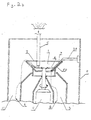
- Fig. 2b shows a partial cross-section view of an embodiment of a separator similar to that shown in fig. 1 using a conical bowl;
- Fig. 3a shows an interaction between a separating surface and two different types of powder particles designated by geometry and/or shape
- Fig. 3b shows an interaction between a separating surface and two different types of powder particles designated by diameter d (by size).
- Fig. 4a shows a side view of another embodiment of a separator for dry separation of powders
- Fig. 4b shows a top view of the embodiment shown in fig. 4a;
- Figs. 5a-5b shows partial views of the discharge device interacting with the rotating surface
- Fig. 5c-5d shows end views of the discharge device in the form of an elastic strip or a brush, and shows the location of a shell, in the form of a powder concentrator, with respect to the discharge device, the discharge device is also shown in the form of a battery of brushes;
- Fig. 6a shows a side view of another embodiment of a separator for dry separation of powders which utilizes separate drive of the feeder disk;
- Fig. 6b shows a side view of one of many possible disk embodiments which utilizes a feeder in the form of a rotating ring;
- Fig. 7 shows a side view of another embodiment of a separator for dry separation of powders utilizing feeding disks (rings) arranged at various levels;
- Fig. 8a shows a side view of another embodiment of a separator for dry separation of powders in which the feeding disks are arranged on an axes which do not coincide with the surface of rotation axis;
- Fig. 8b shows a side view of one of many possible disk embodiments with feeding disks arranged at various levels
- Fig. 8c shows a side view of one of many possible disk embodiments with the axes of feeding disks arranged at an angle to the axis of the surface of revolution;
- Fig. 9a shows a side view of another embodiment of a separator for dry separation of powders with feeding by a nozzle and discharge using a rotating brush;
- Fig. 9b shows a top view of the embodiment shown in fig. 9a;
- Fig. 10a shows a graphite powder distribution in particle size before the separation
- Fig. 10b shows a graphite powder distribution in particle size coarse fraction after separation with particle diameter di ⁇ 10 ⁇ m.
- Fig. 11a shows a fly ash powder distribution in particle size before the separation
- Fig, 11b shows a fly ash powder distribution in particle size fine fraction after separation with particle diameter di ⁇ 40 ⁇ m
- Fig. 12 shows a side view of one of many possible feeding embodiments, here in the form of a feeding conveyer
- Fig. 13a shows a side view of still another embodiment of a discharge device in the form of a pipe with a suction nozzle at the end;
- Fig. 13b shows a front view of the embodiment shown in Fig. 13a.
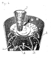
- Fig. 1 shows a simple embodiment of a separator for dry separation of powders.
- a powder representing a mixture of spherical particles (“A" type particles) and cylindrical particles (“B” type particles) is poured, fed, or otherwise delivered etc., through feeding pipe or conduit 5 into the separator.
- the particles e.g., mixture of A and B particles
- the separator provides that disk 6 is rotating when the powder is fed onto its throwing surface.
- the disk 6 rotation at a specific or desired velocity the powder mixture is caused to be thrown outwards against surface 1 of rotating bowl 50.
- the velocity of the outer edge of disk 6 may be in the range of 2Vs > V disk ⁇ Vs, where Vs is the velocity of surface 1 near the feeding zone.
- a zone 54 (see Fig. 3a) is herein designated as a feeding zone and which is located above the rotating bowl surface 1, i.e., zone 54 represents the zone between where the powder leaves the disk 6 and where it contacts surface 1.
- the powder or mixture contacts surface 1 which is rotating (i.e., since bowl 50 is rotating) and due to the frictional engagement or interaction between the powder and the suiface 1, the powder is caused to rotate in the same direction as the bowl 50.
- the spherical particles A are caused to be thrown up and over the edge 2 of bowl 50 or surface 1.
- the roughness of surface 1 should be such that the friction coefficient of the fine/elongated particles (B particles) will be high enough so as to be retained on the surface 1.
- the friction coefficient of the coarse/spherical particles (A particles) is sufficiently low so as to allow them to not be retained by surface 1 such that they roll over the edge 2.
- the bowl is preferably made of stainless steel and surface 1 may preferably comprise coating. This coating may, for example, be a hard surface layer of Aluminum Oxide (Al 2 O 3 ) or other ceramic coatings.
- a zone designated as zone 56 represents a separation zone where the spherical particles ("A" particles) leave the surface 1 after initially contacting the surface 1.
- This zone is the zone where separation takes place and extends from the feeding zone 54 to the discharge zone 58. As discussed above, this length may be 1s (see for example, figure 3b).
- the cylindrical particles B which remain on surface 1 rotate with the bowl 50 on surface 1 and remain thereon until they contact or interact with the discharge device 7.
- the separator includes a discharge device having a bracket end 20 attached to a static or stationary part of the separator, here the outer wall or body 9.
- Discharge device 7 also has a holder end 19 (see Figs. 5b-d).
- Holder end 19 is held rigid by bracket 20 and has a brush 17 or strip 15.
- This brush 17 or strip 15 is designed to rub against surface 1 and acts to sweep surface 1.
- the force of gravity causes the cylindrical particles B to move inwards towards the center axis of the rotating bowl.
- the cylindrical particles pass through this open area to an inner enclosure, channel, or hopper 13. Again, as with the channel or hopper 11 above, the particles may then be conveyed away for further processing.
- Discharge device 7 should extend across substantially the entire surface 1 of rotating bowl 50.
- the discharge device includes brush 17 and extends between rotating disk 6 and rotating bowl 50 via surface 1.
- a zone designated as zone 58 represents a discharge zone where the cylindrical particles are swept off the surface 1 after traveling with surface 1
- the designation of the powder particles as spherical A type particles and cylindrical B type particles is used merely to illustrate the basic operation of the device. That is, a true designation of the different particles is one where the device separates two different types of particles based upon their characteristic ability to frictionally engage the surface 1.
- the particles need not be spherical and/or cylindrical. Rather, they are distinguished by their different frictional interaction with the surface 1 based upon, for example, their shape, size, and density.
- the importance of the invention lies in the separation of at least one type of particle from a mixture of two or more types of particles.
- this distinguishing characteristic may be on the basis of particle diameter when the mixture is essentially one powdered substance which is made up of different size particles of the same substance.
- the invention provides for the distinguishing or the separation of "fine fraction” particles which would act in a manner similar to that shown with respect to the cylindrical B particles (i.e., they are not thrown off the surface, but remain thereon until being brushed off), and "coarse fraction” particles which would act in a manner similar to that shown with respect to the spherical A particles (i.e., get thrown over edge 2).
- the discharge device 7 may be a brush 17 which is static and has brush ends engaging the surface 1 in a sweeping action (based upon relative movement between the brush and the bowl).
- Brush 17 operates in discharge zone 58 (see Fig. 3a) where it sweeps off the fine fraction particles.
- the brush may be oriented at an angle (see Fig. 1) such that a top portion of the brush which engages surface 1 contacts particles traveling on surface 1 before a bottom portion the brush 17. This angle can be optimized to improve the efficiency of the sweeping action on surface 1.
- Fig. 2a shows one embodiment of the separator which operates in a similar manner to that discussed with respect to Fig. 1.
- the separator includes a drive 4 in the form of a motor which can be any conventional motor, and is preferably an electric motor.
- motor 4 rotates a shaft connected to each of the bowl 50 and disk 6.
- motor 4 may rotate the disk 6 and bowl 50 independently so that each of their rotation speeds may be controlled and varied. This can be accomplished, for example, using a transmission attached to the motor or by the use of two motors.
- Disk 6 may take on a variety of configurations for efficiently delivering or feed in the powder to the surface 1, as will be seen in later embodiments.
- disk 6 includes an upper surface which deflects the powder outwards against surface 1.
- disk 6 includes deflection projections which are inwardly disposed to prevent the powder from settling centrally.
- Disk 6 also has a raised deflection outer edge which causes the powder to follow a sloping upward course toward the surface 1. The size and shape of this edge may be varied in an effort to optimize the even distribution of the powder onto surface 1.
- Various internal deflection walls may also be provided to help guide the separated particles into the desired hoppers. This aspect of the invention will be further described later on in other embodiments.
- both the bowl 50 and the disk 6 are connected to the shaft extending from the motor 4. As can be seen by a arrow around the shaft connecting the motor 4 to the disk 6 and bowl 50, the bowl 50 and disk 6 will rotate together. However, body 9, bracket 20, and discharge device 7 do not rotate, but instead are static.
- the invention also contemplates bowls which are essentially flat (i.e., conical as in see Fig. 2b & 4a, for example).
- the discharge device may also be flat so that it has essentially the same profile shape of surface 1.
- other bowl configurations are contemplated such as those which have a wavy or sinusoidal profile (not shown).
- Fig. 2a shows a bowl profile which is essentially concave, however, a convex profile is also contemplated.
- Fig. 3a shows the interaction of the particles with the zones 54, 56, and 58. It should be understood, that the brush 17 does not interact with either zones 54 and 56.
- Zone 54 as described above, represents the space between rotating disk 6 and where the initial powder is fed onto surface 1.
- Zone 56 is a zone which is some distance from where the A particles leave the surface 1 over upper edge 2, these particles being separated from the remaining B particles.
- L represents a distance (in meters) which is traveled by the particles from an initial point when the powder is fed to surface 1 to a point where the B particles get swept off the surface 1.
- the B particles remain on surface 1 and/or continue to interact with surface 1 for a greater distance. As a result they are conveyed with moving surface 1 towards the discharge device 7.
- the point where these B particles contact the discharge device 7 is designated as zone 58.
- zone 58 The point where these B particles contact the discharge device 7 is designated as zone 58.
- the B particles will collide with the discharge device and as a result they are caused to separate from moving surface 1.
- the B particles are swept off moving surface 1 because they collide with the brush 17 and are not allowed to continue to move with surface 1.
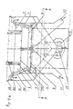
- Figs. 4a and 4b shows another embodiment of a separator in which like components have like reference numbers.
- the separator has rotating body 50 with a cavity 52 open from above and from below with a surface 1 of the cavity 52 being a surface of revolution, namely, a surface of a truncated cone.
- a diameter of the upper edge 2 of the surface 1 is preferably approximately 1000 mm or 1 meter, with the diameter of the lower edge 3 being approximately 800 mm.
- the separator includes a drive 4 with may preferably have a power of approximately 1.5 kW.
- This embodiment uses for example, two feeders, each of them having the form of a powder feeding pipe 5 similar to those described above.
- Each pipe 5 has an outlet end which is located above a peripheral portion of rotating disk 6.
- the outlets of feeding pipes 5 are preferably located along the diameter of the disk 6 at its opposite ends (see Fig. 4b).
- this embodiment utilizes two discharge devices 7 which may similarly be located opposite one another.
- Disk 8 may have a similar design to disk 6 in regards to using centrally disposed deflection protrusions. However, the outer edge deflection would not be required as the B particles are to be conveyed essentially horizontally.
- each of disk 6, disk 8 and bowl 50 may be rotated on a single shaft or arbor. Alternatively, each may be individually rotated by telescoping shafts which are each rotated at different speeds, and which are preferably individually controllable. Again, this may be accomplished with a transmission unit and/or with separate motors and controls.
- the separator preferably is a self contained separating system in the form of a seal enclosure to prevent the escape of powder.
- it preferably has a body portion in the form of an enclosure shell body 9 and includes a lid 10 which is removable or which can be open easily to facilitate maintaining the separator and/or for cleaning the separator.
- the body 9 preferably includes symmetrically arranged hoppers 11 and 12 for collecting the fraction (for example, B particles) discharged by discharge devices 7 from the surface 1.
- hoppers 11 and 12 may be arranged on opposite sides of the separator.
- separator may utilize symmetrically arranged hoppers 13 and 14 for the fraction passing over the upper edge 2 of the surface 1 (for example, A particles) in separation zones 56 in the process of separation.
- While preferred embodiments of the invention employ a brush, other discharge devices could be employed. These include, an elastic strip(s) or wiper blade(s). Additionally, a scraper type device may be employed. The scraper could be made of a hard material which extends across the entire generatrix of surface 1 and located a small distance from it, e.g., approximately 10 to 20 d.
- the discharge device 7 can be in the form of a flat brush 17 (or one having a profile similar to the profile of surface 1) fixed in a holder portion 19 so that the ends of the brush bristles adjoin, contact, sweep, and/or otherwise engage the rotating conical surface 1.
- an elastic strip 15, or a plurality of elastic strips can be fixed in the same position. These may resemble a wiper type device in design (as for example is used on car windshields).
- the strips may be made, for instance, of a fluoropolymer sheet and have an approximate thickness of 0.8 mm. In such a design, an edge of the one or more strips would rub against surface 1 with the end face of its longer side 16.
- These strips may be in the form of blades which are made from flexible material which can deflect somewhat when placed in contact with surface 1 and should have good wear characteristics so that they last a long time since they are held with some pressure continuously against the surface 1.
- the brush 17 or the strip 15 is preferably arranged along the entire length of the generatrix of the surface 1 of revolution and at an angle ⁇ of approximately 15° to the latter.
- elastic strip(s) 15 or brush(s) 17 can be assembled and/or oriented in batteries of several strips (brushes) which are arranged parallel to each other as shown in Figs. 5c-d.
- Strips 15 or brushes 17 may be arranged close to each other (e.g., tight spacing, Fig. 5c) or with an interval or space 18 between the brushes 17 or strips 15 (e.g., loose spacing, Fig. 5d).
- the strips 15 or brushes 17 may be fixed in a holder 19 which is mounted on the body 9 by a bracket 20.
- the discharge device 7 may include a shell 21 which defines an interior space 24 in front of the discharge device 7.
- Shell 21 is preferably attached to the holder 19 at a convenient surface (see Fig. 5c) and extends the entire length of the brush or strip.
- shell 21 functions as a powder concentrator and does not adjoin or contact the surface 1. Instead it has an edge which is separated from surface 1 by a distance 23, this distance being great enough to allow, for example, the B particles to reach the brush 17 or the strip 15.
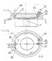
- Figs. 3b illustrates the operation of the separator shown in Figs. 4a-b.
- Fig. 3b is shown a development of a half of the surface 1 of the cavity 52.
- a powder particle(s) 22 is fed by feeding pipe(s) 5 to the periphery of a rotating disk 6 which may be located at a distance of approximately 150 mm below the upper edge 2 of the rotating surface 1.
- the gap between the disk 6 edge and the surface 1 is preferably in the range of approximately 40-45 mm.
- the feeding zone 54 may be, for example, approximately 200 mm long.
- Fine fraction particles have diameters di ⁇ d and therefore remain on the rough surface 1 due to frictional engagement with surface 1, until they reach, together with the surface 1, the discharge zones 58, where discharge devices 7 (e.g., flat brush 17 or strip 15) discharge them so that they fall onto an additional rotating disk 8, which then directs these particles into hoppers 11 and 12 through appropriate through openings between ribs 26 connecting the additional disk 8 with the body 50.
- discharge devices 7 e.g., flat brush 17 or strip 15
- the space in front of the flat brush 17 and above it is surrounded by shell or powder concentrator 21 with a lid 25.
- the powder particles that have passed through the gap 23 become concentrated in the zone 24 (e.g., the brush 17 causes the particles to quickly build up inside shell 21). Thereafter, they travel downwards inside zone 24 and inwards in the direction of the center of the separator, and eventually fall down onto the additional disk 8.
- Figs. 10a-b the results were obtained for graphite powder with the intention of removing a fraction or particle type having a particle size below 10 ⁇ m.
- Fig. 10a shows a size distribution of graphite particles in the initial powder prior to separation.
- Fig. 10b shows a size distribution of particles in the coarse fraction after the separation according to the criterion di ⁇ approximately 10 ⁇ m.
- the device had a process efficiency of about 2 tons per hour.
- the device has the capacity of producing 150 Kg per hour of coarse particles.
- the device can separate 2-8 tons per hour of either graphite or fly ash subject to bowl diameter.
- the initial powder was successfully separated into two fractions, i.e., one with di ⁇ approximately 40 ⁇ m and di ⁇ approximately 40 ⁇ m (wherein di is the separation criteria which is in the domain of the largest particle diameters of the fine fraction and in the domain of the smallest particle diameters of the coarse fraction).
- Fig.11a shows a size distribution of particles in the initial powder
- Fig. 10b shows a size distribution of particles in the fine fraction.
- the process efficiency was about 2 tons per hour.
- Fig. 6a shows another embodiment of the separator.
- the disk 6 utilizes an independent drive 27 which is located above the disk 6. This design allows independent and precise control of the rotation rate of the feeding disk 6.
- the surface 1 is rotated with bottom drive 4 while the disk 6 is independently rotated by top drive 27.
- Fig. 6b shows another embodiment of the invention, which provides for the use of a ring 28 in place of the feeding disk 6.
- disk 6 has a diameter which extends across almost to surface 1.
- the disk has to have sufficient thickness to withstand significant deflection due to gravity and the force of the particles which contact it after leaving feeding pipe 5. This thickness, of course, increases the mass of the disk 6 which places a greater load on the drive 4 and/or 27.
- the design shown in Fig. 6b allows this disk mass to be reduced.
- the disk 6 can be substituted with ring 28, which is fastened to the axle 30 (axle can be driven from a top drive as shown in Fig. 6a or from a bottom drive as shown in Fig. 4a). Between the axle and the ring 28 are a plurality of connecting spokes or ribs 29, their size and quality being sufficient to withstand significant deflection so that the ring 28 remains essentially perpendicular to a center axis of the rotating surface 1.
- Fig. 7 shows still another embodiment of a disk design.
- disk 31 includes a ring 32 which is arranged above the disk 31.
- each of the two feeding pipes 5' direct the powder to either disk 31 or ring 32.
- ring 32 is supported above disk 31 by a plurality of support posts 33.
- This design allows powder exiting from feeding pipe 5 on the right to be feed to a higher section of surface 1 since the powder from this pipe is directed only onto ring 32.
- Feeding pipe 5 on the left directs the powder only onto disk 31 which feeds the powder to a lower section of surface 1.
- powder is fed onto the periphery of the disk 31 by a pipe 5' with a curved end. Simultaneously, more powder is fed to the ring 32 from a straight pipe 5.
- the feeding zone of surface 1 into which powder 22 is thrown from the disk 31 is located below the feeding zone into which powder 22 is thrown from the ring 32.
- the separation conditions for powders thrown from the disk 31 and the ring 32 are different. This makes it possible to improve the separation quality if, for instance, one of fractions obtained after the separation of powder thrown by the disk 31 is used as an initial material fed to the ring 32 for another separation at a higher linear velocity.
- Such a system of arranging the disk 31 and the ring 32 can also be used to separate a powder into a large number of fractions, or alternatively, for the separation of two different powder types.
- the rotation axis of the feeding system disk need not coincide with the rotation axis of the surface 1.
- the invention contemplates another embodiment in which one, two, or several feeding disks 34, each having its own drive 35, can be arranged along the surface 1. In this design, driving the one or more disks from above is preferred.
- Fig. 8a shows an embodiment of the separator with two such disks 34.
- Each disk 34 rotates about a shaft or axle via independent drives 35. Again, as with the previous embodiments, these drives should be separately controllable for speed.
- each is position with respect to feeding pipe 36.
- each disk 34 is also made adjustable not only as to its speed but also as to its vertical position as will be more specifically described herein,
- such disks can be arranged at various heights as shown in Fig. 8b. Additionally, and/or alternatively these disks 34 may also be adjustably arranged at various angles, such as from approximately 45° to 90°, to the rotation axis of the surface 1. Moreover, the powder feeding pipe 36 should be positioned adjacent the periphery of each disk 34 from the side nearest to the surface 1. In yet another embodiment, this design may also utilize the ring design of Fig. 6b in place of one or more disks 34.
- Figs. 9a-b show yet another separator embodiment, wherein the feeding system is in the form of a power feeding pipe 38 having a powder directing nozzle 37.
- the powder enters the feeding zone 54 directly from the nozzle 37.
- Fig. 9a illustrates that more than one pipe may be utilized.
- two feeding pipes 38 with nozzles 37 are oppositely arranged along the surface 1.
- the discharge devices 7 are replaced by cylindrical brushes 38 rotating around their axes via drives 40.
- Each of the brushes 38 again has an independent drive 40 which is separately controllable and movingly adjustable.
- the brush 38 is preferably adjustably mounted at an angle of approximately 20° to the generatrix of the surface of revolution and functions to remove particles of the fine fraction upwards, to the hopper 39.
- the brush 38 is mounted at the same angle to the generatrix of the surface of revolution sloping to the opposite side.
- the rotation direction of the brush 38 can also be made opposite to the rotation direction of surface 1, so that it will discharge fine fraction particles downwards to the additional disk 8 (not shown).
- the cylindrical brush 38 is located inside a shell similar to that shown in figure 5c which at least partially surrounds the brush and acts as a powder concentrator 41.
- Fig, 12 shows still another embodiment of a feeding device in the form of a conveyer 42.
- the powder is fed from the pipe 5 onto a conveying surface which moves the powder towards the surface 1.
- a conveying surface which moves the powder towards the surface 1.
- one of more of these device may be employed to deliver powder from each pipe 5 to surface 1.
- the speed and the drive for this conveyor should be separately adjustable and controllable.
- Fig. 13 shows still another embodiment of a discharge device also can represent a pipe with a suction nozzle 60 at the end, with the nozzle being arranged along the generatrix of the surface of revolution, and rarefaction is created in the pipe and in the nozzle. Air flow sucked in by the nozzle tears powder particles off the cavity surface in the discharge zone and directs them into the nozzle and further, by the pipe, into a hopper.
- the powder separation occurs on a wall of a cavity of a rotating body.
- the body rotates around a vertical axis and has a centrally symmetrical cavity open from above and from below.
- the cavity symmetry axis coincides with the body rotation axis, and the cavity surface is a surface of revolution with circular upper and lower edge's of this cavity, the diameter of the upper circumference being greater that the diameter of the lower circumference.
- powder is fed to a certain zone which is called a feeding zone and which is adjacent to the lower portion of the cavity surface.
- the length of this zone is much less than the length of the separation zone is (preferably 5-9 times smaller than 1s).
- the length of the separation zone is determined by the relationship 1s ⁇ 1gxV/Vg, where 1g is the distance between the lower edge of the feeding zone to the upper edge of the cavity surface along the generatrix of the surface of revolution, and V is the linear velocity of the upper edge 2 of cavity surface 1, and Vg is the velocity of the coarse powder fraction motion upwards along the generatrix of the surface of revolution.
- the diameter of coarse fraction particles can be determined by di ⁇ d, where d is the diameter of particles according to which particles are separated into two fractions. It should be noted that the use of the term "diameter” as used herein, is not to be construed to limit the invention to spherical particles. Rather, it is used to describe the size of the particles.
- the discharge zone Behind the separation zone in the sense of the body rotation, is the discharge zone, where a discharge device facilitates the discharging the powder remaining on the cavity surface. This zone is arranged along the entire generatrix of the surface of revolution.
- the separation proceeds as follows: the powder falls on the rotating surface of a cavity having a certain roughness. Since the resultant of all the forces acting on powder particles is different for large size and small size particles, the larger particles move upward and, during the passage of the separation zone from the feeding zone to the discharge zone, pass up over the upper edge of the cavity surface, and thereafter fall into one of hoppers for collection. The smaller particles on the other hand, remain on the cavity surface by virtue of their interaction with the surface until they reach the discharge device, which at this point discharges them into a respective hopper.
- the powder can be fed to the feeding zone by an appropriately oriented pipe with a nozzle or by a number of rotating disks or rings, or else by a conveyer.
- the rotating disks or rings can have a rotation axis which can either coincide with or be different from the cavity rotation axis.
- each of the rotating surface 1 or the disks/rings can be driven by the same drive or have an independent drives. Additionally, these disks may be located in a plane perpendicular to the cavity rotation axis, or in some other plane. These disks may also be located in the same plane or positioned one under another.
- powder is fed by a pipe to the periphery of the rotating disk or ring and thrown into the feeding zone under the action of the centrifugal force.
- the discharge device represent a flat or round brush adjoining the rotating, cavity surface.
- the brushes can be adjustably fixed so as to be movable in longitudinal or transverse direction and can be either static or adapted to rotate around their axes.
- the discharge device can comprise one brush or several brushes located at various distances form one another.
- the discharge device can represent a flexible elastic strip with one of end faces adjoining the cavity surface.
- the discharge device also can represent a pipe with a suction nozzle at the end; the nozzle is arranged along the generatrix of the surface of revolution, and rarefaction is created in the pipe and in the nozzle. Air flow sucked in by the nozzle tears powder particles off the cavity surface in the discharge zone and directs them into the nozzle and further, by the pipe, into a hopper.
Landscapes
- Combined Means For Separation Of Solids (AREA)
Applications Claiming Priority (2)
| Application Number | Priority Date | Filing Date | Title |
|---|---|---|---|
| US506275 | 1983-06-21 | ||
| US09/506,275 US6439394B1 (en) | 2000-02-17 | 2000-02-17 | Separator for dry separation of powders |
Publications (2)
| Publication Number | Publication Date |
|---|---|
| EP1125645A2 true EP1125645A2 (fr) | 2001-08-22 |
| EP1125645A3 EP1125645A3 (fr) | 2002-12-11 |
Family
ID=24013917
Family Applications (1)
| Application Number | Title | Priority Date | Filing Date |
|---|---|---|---|
| EP01400419A Withdrawn EP1125645A3 (fr) | 2000-02-17 | 2001-02-16 | Séparateur pour la séparation à sec de poudres |
Country Status (2)
| Country | Link |
|---|---|
| US (1) | US6439394B1 (fr) |
| EP (1) | EP1125645A3 (fr) |
Cited By (3)
| Publication number | Priority date | Publication date | Assignee | Title |
|---|---|---|---|---|
| US7708145B2 (en) | 2003-05-18 | 2010-05-04 | Tangshan Shenzhou Machinery Co., Ltd. | Dry separating table, a separator and equipment for the compound dry separation with this table |
| CN108339753A (zh) * | 2018-03-24 | 2018-07-31 | 新乡市振英机械设备有限公司 | 一种利于环保的生活垃圾处理用重轻物质分离器 |
| CN111842317A (zh) * | 2020-07-20 | 2020-10-30 | 温州大学 | 自动清洗式采茶容纳装置 |
Families Citing this family (13)
| Publication number | Priority date | Publication date | Assignee | Title |
|---|---|---|---|---|
| US6726026B1 (en) * | 2001-08-20 | 2004-04-27 | Lawrence Edwin Wilkerson | Seed husk separator |
| US20040231566A1 (en) * | 2003-05-20 | 2004-11-25 | Cemex Inc. | Process for Fly Ash Beneficiation |
| WO2011143776A1 (fr) * | 2010-05-20 | 2011-11-24 | Kayden Industries Inc. | Séparateur centrifuge à axe vertical |
| FR3003778B1 (fr) * | 2013-03-27 | 2015-03-27 | Heraeus Materials Tech Gmbh | Procede et dispositif de tri de billes |
| US10407607B2 (en) * | 2015-04-08 | 2019-09-10 | Gumpro Drilling Fluid PVT. LTD | Solid invert emulsion drilling fluid additives, methods of preparation and use in oil-based drilling fluids |
| US11162009B2 (en) | 2015-04-08 | 2021-11-02 | Gumpro Drilling Fluid Pvt. Ltd. | Lubricant additives for water based drilling fluid |
| CN106238391B (zh) * | 2016-08-16 | 2018-09-21 | 柳州市旭邦科技有限公司 | 一种清洗分选机控制系统 |
| CN106269635B (zh) * | 2016-08-16 | 2018-09-21 | 柳州市旭邦科技有限公司 | 一种清洗分选机 |
| CN108526023B (zh) * | 2018-05-07 | 2023-12-19 | 成都安好精工机械股份有限公司 | 一种弹簧分离装置 |
| CN110508492B (zh) * | 2019-08-30 | 2024-05-14 | 东北大学 | 一种圆盘选矿机 |
| CN113941508B (zh) * | 2021-10-15 | 2023-06-02 | 四川德胜集团钒钛有限公司 | 一种矿石分筛机 |
| CN115090507B (zh) * | 2022-07-14 | 2022-11-15 | 中节能(达州)新材料有限公司 | 一种玻璃微珠圆度筛选平台 |
| CN117181460A (zh) * | 2023-09-18 | 2023-12-08 | 青岛华腾石墨科技有限公司 | 一种粉体收集过滤装置 |
Family Cites Families (42)
| Publication number | Priority date | Publication date | Assignee | Title |
|---|---|---|---|---|
| US379133A (en) | 1888-03-06 | Charles d | ||
| US489101A (en) | 1893-01-03 | Ieaxsforand process of separating metals from ores | ||
| US621306A (en) | 1899-03-14 | l kneeland | ||
| US471614A (en) | 1892-03-29 | Centrifugal starch refining and separating machine | ||
| US1322139A (en) | 1919-11-18 | Centrifugal concentrator | ||
| US556567A (en) | 1896-03-17 | John b | ||
| US736976A (en) | 1900-09-21 | 1903-08-25 | Henry B Keiper | Centrifugal creamer. |
| US726948A (en) | 1902-03-26 | 1903-05-05 | O H P Baxter | Centrifugal ore-separator. |
| US1283846A (en) | 1916-02-18 | 1918-11-05 | Allen M Mark | Centrifugal separator. |
| US1216118A (en) | 1916-07-06 | 1917-02-13 | George Hering | Ore-separator. |
| US1473421A (en) | 1919-04-05 | 1923-11-06 | Centrifugal Nat Concentrator C | Centrifugal separator |
| US1599502A (en) | 1924-05-27 | 1926-09-14 | Thomassen Hermanus | Centrifugal separator |
| US1594501A (en) | 1925-04-02 | 1926-08-03 | Earle S Eccleston | Centrifugal separator |
| US1712184A (en) | 1926-10-07 | 1929-05-07 | Reinhold M Wendel | Centrifugal concentrator |
| US1684870A (en) | 1927-10-17 | 1928-09-18 | Frank D Lewis | Centrifugal concentrating and amalgamating apparatus of the vertical type |
| US1750860A (en) | 1929-06-08 | 1930-03-18 | Edmond M Beus | Gold separator |
| US1896180A (en) | 1930-03-22 | 1933-02-07 | Centrifugal Engineering And Pa | Multiple centrifugal separator |
| US1935547A (en) | 1932-09-07 | 1933-11-14 | Samucl J Dryhurst | Ore separator |
| US1988500A (en) | 1933-04-27 | 1935-01-22 | Lack Sydney Walter | Machine for concentrating ores and amalgamating gold ores |
| US2056888A (en) | 1934-04-12 | 1936-10-06 | American Centrifugal Corp | Centrifugal separating machine |
| US2112099A (en) | 1935-11-01 | 1938-03-22 | Ballou John Mck | Ore concentrator |
| US2230013A (en) | 1936-05-04 | 1941-01-28 | American Centrifugal Corp | Centrifugal separating equipment |
| US2415210A (en) | 1944-06-20 | 1947-02-04 | Hoefling Eugene | Centrifuge for separating molten metals from slag |
| US2472475A (en) | 1946-06-21 | 1949-06-07 | Hamilton Tolbert | Centrifugal amalgamator |
| US2692832A (en) | 1952-02-15 | 1954-10-26 | Swift & Co | Cheese curd mechanical processing |
| GB757994A (en) * | 1953-04-01 | 1956-09-26 | Albert Brice | Improved apparatus for sorting weeds, stones and the like from potatoes or other crops or vegetables |
| US3256993A (en) | 1963-10-17 | 1966-06-21 | Hein Lehmann & Co A G | Centrifuge |
| DE1226793B (de) | 1965-04-09 | 1966-10-13 | Richard Steimel | Zentrifuge zum kontinuierlichen Entoelen von Metallspaenen |
| US3485360A (en) * | 1967-08-11 | 1969-12-23 | Atomic Energy Commission | Particle separator |
| FR1459673A (fr) | 1968-12-19 | 1966-11-18 | Combustion Eng | Procédé et appareil pour la mise en contact d'un liquide et d'un gaz |
| US3672646A (en) * | 1971-04-15 | 1972-06-27 | Detroit Tool & Eng Co | Pneumatic cement gun machine |
| US3932442A (en) | 1973-08-27 | 1976-01-13 | Lundy Electronics & Systems, Inc. | Process for screening materials with vibrating screens |
| US3941687A (en) | 1974-09-26 | 1976-03-02 | Air Products And Chemicals, Inc. | Solids separation |
| US4072266A (en) | 1975-06-19 | 1978-02-07 | Braunschweigische Maschinenbauanstalt | Centrifuge, especially for the sugar industry |
| US4608040A (en) | 1983-07-05 | 1986-08-26 | Knelson Benjamin V | Centrifugal separator |
| DE3621221A1 (de) | 1986-06-25 | 1988-01-14 | Pfeiffer Fa Christian | Verfahren zur windsichtung und windsichter |
| DE3933136A1 (de) | 1989-10-04 | 1991-04-18 | Krupp Buckau Maschinenbau Gmbh | Verfahren und vorrichtung zum schleudern eines hochviskosen schleudergutes |
| US5222933A (en) | 1992-03-20 | 1993-06-29 | Benjamin V. Knelson | Centrifual discharge of concentrate |
| NO300257B1 (no) | 1995-04-07 | 1997-05-05 | Sinvent As | Apparat for sortering av partikkelformig materiale |
| US5895345A (en) | 1996-12-09 | 1999-04-20 | Knelson; Benjamin | Centrifugal separator with a reduced number of fluidized recesses |
| US6095965A (en) * | 1997-08-06 | 2000-08-01 | Sortech Separation Technologies Ltd. | Centrifugal separator for dry components |
| US6244446B1 (en) * | 1999-10-08 | 2001-06-12 | Richard L. Schmittel | Method and apparatus for continuously separating a more dense fraction from a less dense fraction of a pulp material |
-
2000
- 2000-02-17 US US09/506,275 patent/US6439394B1/en not_active Expired - Fee Related
-
2001
- 2001-02-16 EP EP01400419A patent/EP1125645A3/fr not_active Withdrawn
Cited By (4)
| Publication number | Priority date | Publication date | Assignee | Title |
|---|---|---|---|---|
| US7708145B2 (en) | 2003-05-18 | 2010-05-04 | Tangshan Shenzhou Machinery Co., Ltd. | Dry separating table, a separator and equipment for the compound dry separation with this table |
| CN108339753A (zh) * | 2018-03-24 | 2018-07-31 | 新乡市振英机械设备有限公司 | 一种利于环保的生活垃圾处理用重轻物质分离器 |
| CN111842317A (zh) * | 2020-07-20 | 2020-10-30 | 温州大学 | 自动清洗式采茶容纳装置 |
| CN111842317B (zh) * | 2020-07-20 | 2021-08-17 | 温州大学 | 自动清洗式采茶容纳装置 |
Also Published As
| Publication number | Publication date |
|---|---|
| US6439394B1 (en) | 2002-08-27 |
| EP1125645A3 (fr) | 2002-12-11 |
Similar Documents
| Publication | Publication Date | Title |
|---|---|---|
| US6439394B1 (en) | Separator for dry separation of powders | |
| CN100457282C (zh) | 高压静电分选器和分离器及相关方法 | |
| US4528091A (en) | Particle classifier | |
| CN1083545A (zh) | 把粉末镀到工件上的方法和设备 | |
| JP2013537475A (ja) | コロナ放電による電子分離法 | |
| US4059189A (en) | Classification of particles | |
| AU674011B2 (en) | Coal pulverizer purifier classifier | |
| US20050224613A1 (en) | Grinder | |
| EP0262124B1 (fr) | Separateur rotatif | |
| US5195640A (en) | Method and apparatus for cleaning abrasive blast media | |
| CN201061774Y (zh) | 塑料静电分检系统 | |
| CN112934376B (zh) | 一种具有粒序分级功能的稀土电机型磨煤机 | |
| US4931173A (en) | Apparatus and method for removing debris from granular material | |
| JP4058706B2 (ja) | 粉状原料の分級方法および円筒スクリーン分級機 | |
| KR19980701206A (ko) | 분급 장치(Classifier) | |
| CN210159963U (zh) | 节能气流选粉机 | |
| US6383263B1 (en) | Device intended for mechanical separation of high-temperature sand present in a gas stream | |
| RU2142859C1 (ru) | Способ и устройство для пневмообогащения сырья, содержащего тяжелые минералы и металлы | |
| CA2010897A1 (fr) | Crible | |
| JP2831950B2 (ja) | ブラスト加工における研磨材供給方法および装置 | |
| US11897000B2 (en) | Device for sorting powder particles | |
| JPH0829265B2 (ja) | 粒体選別装置 | |
| US919291A (en) | Apparatus for grading granular substances. | |
| CN222642227U (zh) | 一种双分离且同时回收细粉的装置 | |
| RU2278020C1 (ru) | Устройство для регенерации абразивной среды при абразивно-струйной обработке |
Legal Events
| Date | Code | Title | Description |
|---|---|---|---|
| PUAI | Public reference made under article 153(3) epc to a published international application that has entered the european phase |
Free format text: ORIGINAL CODE: 0009012 |
|
| AK | Designated contracting states |
Kind code of ref document: A2 Designated state(s): AT BE CH CY DE DK ES FI FR GB GR IE IT LI LU MC NL PT SE TR |
|
| AX | Request for extension of the european patent |
Free format text: AL;LT;LV;MK;RO;SI |
|
| PUAL | Search report despatched |
Free format text: ORIGINAL CODE: 0009013 |
|
| AK | Designated contracting states |
Kind code of ref document: A3 Designated state(s): AT BE CH CY DE DK ES FI FR GB GR IE IT LI LU MC NL PT SE TR |
|
| AX | Request for extension of the european patent |
Free format text: AL;LT;LV;MK;RO;SI |
|
| 17P | Request for examination filed |
Effective date: 20030526 |
|
| AKX | Designation fees paid |
Designated state(s): AT BE CH CY DE DK ES FI FR GB GR IE IT LI LU MC NL PT SE TR |
|
| 17Q | First examination report despatched |
Effective date: 20040401 |
|
| STAA | Information on the status of an ep patent application or granted ep patent |
Free format text: STATUS: THE APPLICATION IS DEEMED TO BE WITHDRAWN |
|
| 18D | Application deemed to be withdrawn |
Effective date: 20040812 |