EP1125657A2 - Verfahren und Anlage zum Giessen von Vorprodukten in einer Stranggiessanlage - Google Patents
Verfahren und Anlage zum Giessen von Vorprodukten in einer Stranggiessanlage Download PDFInfo
- Publication number
- EP1125657A2 EP1125657A2 EP01103849A EP01103849A EP1125657A2 EP 1125657 A2 EP1125657 A2 EP 1125657A2 EP 01103849 A EP01103849 A EP 01103849A EP 01103849 A EP01103849 A EP 01103849A EP 1125657 A2 EP1125657 A2 EP 1125657A2
- Authority
- EP
- European Patent Office
- Prior art keywords
- speed
- drive
- casting
- rollers
- torque
- Prior art date
- Legal status (The legal status is an assumption and is not a legal conclusion. Google has not performed a legal analysis and makes no representation as to the accuracy of the status listed.)
- Granted
Links
Images


Classifications
-
- B—PERFORMING OPERATIONS; TRANSPORTING
- B22—CASTING; POWDER METALLURGY
- B22D—CASTING OF METALS; CASTING OF OTHER SUBSTANCES BY THE SAME PROCESSES OR DEVICES
- B22D11/00—Continuous casting of metals, i.e. casting in indefinite lengths
- B22D11/04—Continuous casting of metals, i.e. casting in indefinite lengths into open-ended moulds
- B22D11/0405—Rotating moulds
Definitions
- the invention relates to a method for casting primary products, in particular from steel materials such as slabs, blooms, beam blanks or the like in a continuous caster, with one downstream of the casting mold, if necessary in segments divided strand guide, consisting of pairs opposite each other Roles for supporting and promoting the solidifying cast strand, whereby at least one of these roles with a drive, the drive role, for transmission of both executives and strand conveyors working together with dragged rollers pressed against the cast strand with a defined contact force becomes.
- the invention also relates to a plant for carrying out the method.
- driven Rollers It is known to ensure the frictional connection between driven Rollers and a strand of hydraulically or mechanically adjustable lifting beams to use. These are often used, especially to avoid quality degradation on the cast end product, applied with a force below the compressive force that can be generated by the strand itself according to its hydraulic Height (ferrostatic pressure). This is to avoid strand deformations become.
- the driven rollers are also rigid in the support frame built in or integrated.
- EP 0 908 256 A1 describes a method and an installation for generating of slabs in a continuous caster, with one downstream of the casting mold, strand guide formed from two-part segments, in which the cast strand by rolling from the vertical casting direction into the horizontal rolling direction is promoted and supported.
- those for the transfer of the Conveying forces required adjusting forces for the drive rollers in general Hydraulic cylinders applied.
- the hydraulic is proposed Clamping cylinder, which the two segment frame parts against spacers with each other braced to be replaced by segment adjusting cylinders, reducing the adjusting forces for the drive roller to the segment inlet or outlet and the forces for the strand conveyance are also applied by the segment actuating cylinders become.
- strand guide scaffolds in segment design such as a z. B. in DE 19th 63 146 C1 described arch system, which the cast strand from the vertical
- the upper and lower frames are the casting direction in the horizontal rolling direction the segments by four arranged at the corners outside the cast strand, hydraulic cylinders connecting the frames braced against each other.
- Different strand thicknesses are set using spacers, against which the frame parts are pressed. A change in the roller spacing this construction is not possible during the casting process.
- DE 43 06 853 C2 proposes between the spacers and to arrange a hydraulic plunger cylinder for the respective side frame part, and the ring piston to be dimensioned so that he in the pressure-relieved state Segment parts fixed on the distance of the rolls, the desired strand thickness corresponds.
- This measure does indeed lead to an adjustment of the leadership role possible on different strand thicknesses, but this design requires that at least one of the rollers, the drive roller, through its own hydraulic jack cylinders (usually two per drive roller) with the required force for the transmission of the strand conveying forces is pressed against the cast strand.
- the object of the invention based, a guide of the cast strand, preferably from the vertical casting direction in the horizontal rolling direction, to improve that one at gradual wear and tear on the rollers over the course of the operating time the transferable pull-out force can be foresightedly recognized by timely initiation of preventive maintenance an operational accident, For example, to avoid the strand getting stuck in the casting machine.
- the achievement of the object is in the preamble of claim 1 method called the measure that all drives to a predetermined Speed are regulated so that their peripheral speeds are the same within the limits of a proposed casting speed and the associated motor torques (motor torques) relative to the load capacity the strand shell at a level that is as uniform as possible below one permissible limit torque are maintained, and that to determine the permissible Limit torque initially on a single drive of the system, while all other drives regulate the specified target casting speed, that Drive torque, starting at zero, increases steadily while the speed of the Drive roller monitored, and with a disproportionate increase in speed A the limit torque B is determined and the process is terminated.
- the measured immediately before the speed increase A Limit torque B with associated speed (slip torque and slip speed) taking into account boundary conditions such as steel quality, casting speed, Casting format, spray schedule or the like in relation to the measured Role is stored in a memory for later evaluation.
- an embodiment of the method according to the invention provides that the determined memory data are entered into an evaluation module, which includes the determined parameters for slip torque and slip speed the pouring boundary conditions linear or square, e.g. B. by the method the least squares of errors, correlated, and a trend curve that can be created with it with a curve determined from experiments or theoretical considerations for the adhesion limit, the trend curve being compared with the limit curve Y is brought to the intersection and the intersection position the remaining time until designated to reach the functional limit of the drive rollers, and being planned Operating programs such as maintenance times etc. are taken into account. there the prediction accuracy increases when an approximation is as far as possible to the permissible limit, and the evaluation preferably in one Process computer of the system with automatic data transmission.
- the speed control of a strand guide of the type mentioned with subordinate torque control (load balancing control), with the primary all drives are regulated to one speed so that their peripheral roll speed are the same within the permitted limits, but at the same time also the motor currents (motor torques), relative to the load capacity of the strand shell be kept at the same level as possible within the facility.
- a system for the casting of preliminary products, in particular from steel materials of the type mentioned in the preamble of claim 1, for performing the method according to the invention comprises means for storing and transmitting measurement data, in particular the drivable roles and, if applicable, the ones that can be assigned to them Segments, on a data acquisition system of the plant.
- the data acquisition system include an algorithm unit for linking the average wear of towed rollers with that of the driven ones Roles comprises, the algorithm unit with an information unit for Operating data, e.g. from operational tests or from theoretical calculations is technically linked based on the state of the art.
- FIG. 1 shows a strand guide 10 of a continuous casting plant, for example for thin slabs, comprising a number of roller segments 14, 14 ', by means of which a Cast strand 12 emerging from the mold 11 by means of opposing one another Rollers 13, in an arc shape from the casting direction in the horizontal rolling direction 15 guided and conveyed by means of drive rollers 13 '.
- roller segments 14, 14 ' one of the rollers 13, for example in the Segment 3 and 4, formed as a drive roller 13 'with drive means and on the Arranged inside the bow of the strand guide 10. With subsequent Roll segments 5 to 8 are two opposite each other in the middle of the segment Drive rollers 13 'are provided which support and promote the strand.
- roller segments 10, 11, 12 In the subsequent horizontal runout of the strand 12 are the roller segments 10, 11, 12 also with opposing driven roller pairs 13 'provided.
- FIG. 2 shows a roller segment 14 designed according to the prior art, 14 'with a drive roller 13', driven by the motor 21 via the gear 22 and the drive shaft 23.
- the roller segment 14, 14 ' consists of a segment upper frame 16, which pressed against the segment subframe 18 by means of hydraulic clamping cylinders 17 becomes. Spacers 19 are provided for a constant distance the frame parts 16, 18 care for each other.
- the one in the middle of the segment 14, 14 'in the upper segment frame 16 arranged drive roller 13' applies the strand 12, according to the graph in Figure 3, the required Strand conveying forces 26 ', whereas the other rollers 13 of the segment frame 16, 18 the clamping forces 26 required for segment bracing, apply so that the rollers 13, which are supported in the segment frame parts 16, 18, 13 'their functions as supporting and conveying elements for transporting the cast strand 12 in the conveying direction 15 can meet.
- Figures 4 and 5 show a segment 14, 14 ', also of a type according to State of the art.
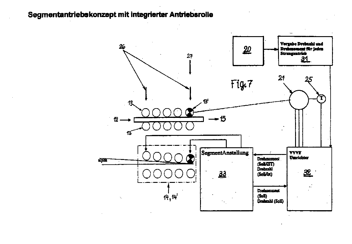
- a segment drive concept with integrated drive roller 13 'and means for Implementation of the invention can be seen in the overview of FIGS. 6 to 8.
- the diagram in FIG. 8 first shows the normal operating case constant speed and constant torque, until the end of the horizontal Course at the intersection with the vertical line Y. In the subsequent, initially steady increase in an acceleration curve with approximately quadratic Rise, the intersection A with the vertical line G at the Limit speed reached.
- This limit speed is characteristic in that it corresponds to it Limit torque, then at the intersection B with the limit line G disproportionately falls off.
- the data acquisition system 20 of the installation is a first Computing unit 31 for specifying the speed and torque for each strand drive owns, and at least one with the engine 21 via a drive roller 30 'coupled second computing unit 32 with means for the TARGET / ACTUAL comparison of speed and torque in cooperation with a third arithmetic unit 33 for regulating the required segment settings through the adjusting cylinders 17, 17 ', both for the basic functions, namely employment 26 for temperature shrinkage and soft reduction of the roller segment 14, 14 ', and also according to arrow 27 for the additional functions according to the invention such as slip diagnosis and maximizing the drive torque.
- a temperature sensor 25 is connected.
Landscapes
- Engineering & Computer Science (AREA)
- Mechanical Engineering (AREA)
- Continuous Casting (AREA)
- Moulding By Coating Moulds (AREA)
- Organic Low-Molecular-Weight Compounds And Preparation Thereof (AREA)
Abstract
Description
- Figur 1
- Die Strangführung einer Stranggießanlage mit Rollensegmenten nach dem Stand der Technik;
- Figur 2
- einen Schnitt durch ein Rollensegment nach dem Stand der Technik mit dargestelltem Antrieb;
- Figur 3
- eine graphische Darstellung der aufzubringenden Kräfte auf ein Rollensegment entsprechend Figur 2;
- Figur 4
- einen Schnitt durch ein Rollensegment mit in die Segmentanstellung durch endständige Anstellzylinder integrierter Antriebsrolle;
- Figur 5
- eine graphische Darstellung der aufzubringenden Kräfte auf ein Rollensegment entsprechend Figur 4;
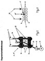
- Figur 6
- einen Schnitt durch ein Rollensegment gemäß Erfindung mit endständig angetriebener integrierter Antriebsrolle;
- Figur 7
- eine graphische Darstellung zur Ermittlung vom Grenzmoment mit zugehöriger Drehzahl (Schlupfmoment und Schlupfdrehzah);
- Figur 8
- eine graphische Darstellung einer erfindungsgemäßen Antriebsmomentendiagnose für normalen Betriebsfall bzw. für Drehzahlerhöhung bis zur Grenzdrehzahl bzw. Grenzmoment.
- unvorhergesehene Ausförderprobleme des Stranges aufgrund des Verschleißes von angetriebenen Rollen zu vermeiden,
- auf einen prophylaktischen Austausch von Rollen bzw. ihren Traggerüsten oder Segmenten ganz zu verzichten und Wartung nur dann vorzunehmen, wenn sie physikalisch erforderlich ist oder
- das zu vergießende Produktionsprogramm auf die aktuellen Ausziehkraftreserve anzupassen,
- langfristig Erfahrungen über die Verschleißhistorie der Gießmaschine zu sammeln
und damit
- einerseits die im Verfahren erforderlichen Grenzkriterien und
- andererseits beispielsweise auch die eingesetzten Rollenwerkstoffe oder
- das Betriebsprogramm der Anlage
- den Einsatz von nicht angestellten Antriebsrollen für den Betreiber einschätzbar und infolgedessen sicher zu machen und damit die Investition sowie Betriebskosten zu senken,
- bei maschinenzugeordeten Speichermedien gleichzeitig noch weitere Informationen über den Lebenszyklus der Einrichtung zu erhalten und die damit die vorausschauende Wartung treffsicherer zu machen;
- bei Einsatz von nicht angestellten Antriebsrollen die maximal mögliche Antriebsleitung durch Veränderung des Anstellwinkels kurzzeitig (bei Ausförderproblemen) zur Verfügung zu stellen. Hierbei kann das Prinzip der Anti-Schlupf-Regelung ergänzend zur Anwendung gebracht werden.
- 10
- Strangführung
- 11
- Kokille
- 12
- Gussstrang
- 13
- Rollen
- 13'
- Rollen mit Antrieb
- 14
- Rollensegment
- 15
- Förderrichtung
- 16
- Segmentoberrahmen
- 17
- Hydraulikklemmzylinder
- 17'
- Segmentanstellzylinder
- 18
- Segmentunterrahmen
- 19
- Distanzstück
- 20
- Datenerfassungssystem
- 21
- Motor
- 22
- Getriebe
- 23
- Gelenkwelle
- 24
- Speicherchips
- 25
- Temperatursensor
- 26
- Anstellkräfte
- 26'
- Strangförderkräfte
- 27
- Strangförderkraft
- 31
- Recheneinheit
- 32
- Recheneinheit
- 33
- Recheneinheit
Claims (9)
- Verfahren zum Gießen von Vorprodukten insbesondere aus Stahlwerkstoffen wie Brammen, Vorblöcken, Beam Blanks oder dgl., in einer Stranggießanlage mit einer der Gießkokille (11) nachgeordneten, ggfs. in Segmente (14, 14') unterteilten Strangführung (10), bestehend aus paarweise einander gegenüberliegende Rollen (13, 13') zur Stützung und Förderung des erstarrenden Gussstranges (12), wobei mindestens eine dieser Rollen (13, 13') mit einem Antrieb, die Antriebsrolle (13'), zur Übertragung von sowohl Führungs-, als auch Strangförderkräften im Zusammenwirken mit geschleppten Rollen mit definierter Anstellkraft gegen den Gussstrang (12) gedrückt wird,
dadurch gekennzeichnet,
dass alle Antriebe (21 - 23) bzw. Antriebsrollen (13') auf eine vorgegebene Drehzahl derart geregelt werden, dass ihre Rollenumfangsgeschwindigkeit innerhalb der Grenzen einer vorgesehenen Gießgeschwindigkeit gleich sind und die zugehörigen motorischen Drehmomente (Motormomente) relativ zur Belastbarkeit der Strangschale auf möglichst gleichmäßigem Niveau unterhalb eines zulässigen Grenzmomentes gehalten werden, und dass zur Ermittlung des zulässigen Grenzmomentes, zunächst an einem einzelnen Antrieb der Anlage, während alle anderen Antriebe die vorgegebene SOLL-Giessgeschwindigkeit ausregeln, das Antriebsmoment, beginnend bei Null, stetig gesteigert und dabei die Drehzahl der Rolle (13') überwacht, und bei einer überproportionalen Steigerung der Drehzahl (A) das Grenzmoment (B) festgestellt und der Vorgang abgebrochen wird. - Verfahren nach Anspruch 1,
dadurch gekennzeichnet,
dass das unmittelbar vor der Drehzahlsteigerung (A) gemessene Grenzmoment (B) mit zugehöriger Drehzahl (Schlupfmoment und Schlupfdrehzahl) unter Berücksichtigung von Randbedingungen wie Stahlqualität, Gießgeschwindigkeit, Gießformat und Spritzplan oder dgl. in Bezug auf die vermessene Rolle (13') in einem Speicher (24) für spätere Auswertung abgelegt wird. - Verfahren nach einem der Ansprüche 1 oder 2,
dadurch gekennzeichnet,
dass die Messung der Grenzdrehzahl (A) sowie des Grenzmomentes (B) und deren Abspeicherung sukzessive für alle angetriebenen Rollen der Anlage durchgeführt und die Messungen entweder manuell oder nach Programm durchgeführt werden, wobei die Messungen sequentiell wiederholt und wenigstens je einmal nach einer ausreichend langen Einlaufzeit der Anlage bei abgesenkter Gießgeschwindigkeit auf einem durcherstarrten Bereich des Gussstranges (12) durchgeführt werden. - Verfahren nach Anspruch 3,
dadurch gekennzeichnet,
dass die vorgenannten Messungen in jeder Sequenz, zwischen Anguss und Gießende, oder je einmal innerhalb eines festzulegenden Zeitraumes, längstens jedoch mit Monatsabständen, durchgeführt werden. - Verfahren nach einem oder mehreren der Ansprüche 1 bis 4,
dadurch gekennzeichnet,
dass die Speicherdaten einem Auswertemodul eingegeben werden, dass die ermittelten Parameter für Schlupfmoment und Schlupfdrehzahl einschließlich der Gießrandbedingungen linear oder quadratisch, z. B. nach der Methode der kleinsten Fehlerquadrate, korreliert, und eine damit erstellbare Trendkurve mit einer aus Versuchen oder theoretischen Überlegungen ermittelten Kurve für die Haftgrenze verglichen wird, wobei die Trendkurve mit der Grenzkurve (Y) zum Schnitt gebracht wird, und deren Schnittpunkte die noch verbleibende Zeit bis zum Erreichen der Funktionsgrenze der Antriebsrollen (13') bezeichnen, wobei geplante Betriebsprogramme, Wartungszeiten etc. berücksichtigt werden. - Anlage zum Gießen von Vorprodukten, insbesondere aus Stahlwerkstoffen der im Oberbegriff von Anspruch 1 genannten Art, zur Durchführung des Verfahrens nach der Erfindung, umfassend Mittel zum Speichern und Übertragen von Messdaten, insbesondere der antreibbaren Rollen (13') auf ein Datenerfassungssystem (20) der Anlage,
dadurch gekennzeichnet,
dass das Datenerfassungssystem (20) eine Algorithmuseinheit zur Verknüpfung des mittleren Verschleisses geschleppter Rollen mit dem der angetriebenen Rollen (13') umfasst, wobei die Algorithmuseinheit mit einer Informationseinheit für Betriebsdaten bspw. aus Betriebsversuchen, oder aus theoretischen Berechnungen auf Basis des Standes der Technik, datentechnisch verknüpft ist. - Anlage nach Anspruch 6,
dadurch gekennzeichnet,
dass der Prozessrechner (20) eine erste Einheit (31) zur Lastenausgleichsregelung durch Vorgabe von Drehzahl und Drehmoment an alle Rollenantriebe (13') besitzt, die mit einer zweiten Einheit (32) mit Mitteln zum SOLL/IST-Vergleich von Drehzahl und Drehmoment gekoppelt ist und die mit dem Motor (21) zumindest über eine Antriebsrolle (13') verbunden ist, wobei die zweite Einheit (32) mit einer dritten Einheit (33) zur Regelung einer erforderlichen Segment-Anstellung durch Anstell-Zylinder (17, 17') sowohl für die Anstellung (26) für Temperaturschrumpf und Softreduktion, als auch für die Anstellung (27) für die Schlupfdiagnose des Antriebsmomentes, zusammenwirkt. - Anlage nach einem oder mehreren der Ansprüche 6 oder 7,
dadurch gekennzeichnet,
dass der zweiten Einheit (32) des Prozeßrechners (20) ein Temperatursensor (25) aufgeschaltet ist. - Anlage nach einem oder mehreren der Ansprüche 6 bis 8,
dadurch gekennzeichnet,
dass jedem mit einer Antriebsrolle (13') zur Antriebsmomentdiagnose versehenen Rollensegment (14, 14') ein individueller Datenspeicherchip (24) zugeordnet ist.
Applications Claiming Priority (2)
| Application Number | Priority Date | Filing Date | Title |
|---|---|---|---|
| DE10007706 | 2000-02-19 | ||
| DE10007706A DE10007706A1 (de) | 2000-02-19 | 2000-02-19 | Verfahren und Anlage zum Gießen von Vorprodukten in einer Stranggießanlage |
Publications (3)
| Publication Number | Publication Date |
|---|---|
| EP1125657A2 true EP1125657A2 (de) | 2001-08-22 |
| EP1125657A3 EP1125657A3 (de) | 2003-09-10 |
| EP1125657B1 EP1125657B1 (de) | 2005-01-19 |
Family
ID=7631615
Family Applications (1)
| Application Number | Title | Priority Date | Filing Date |
|---|---|---|---|
| EP01103849A Expired - Lifetime EP1125657B1 (de) | 2000-02-19 | 2001-02-16 | Verfahren und Anlage zum Giessen von Vorprodukten in einer Stranggiessanlage |
Country Status (7)
| Country | Link |
|---|---|
| US (2) | US6371197B2 (de) |
| EP (1) | EP1125657B1 (de) |
| JP (1) | JP4842444B2 (de) |
| AT (1) | ATE287304T1 (de) |
| CA (1) | CA2337451C (de) |
| DE (2) | DE10007706A1 (de) |
| MX (1) | MXPA01001831A (de) |
Cited By (3)
| Publication number | Priority date | Publication date | Assignee | Title |
|---|---|---|---|---|
| EP1249288A3 (de) * | 2001-04-11 | 2002-12-18 | SMS Demag AG | Verfahren und Vorrichtung zur Kontrolle der Antriebskräfte bei Stranggiessanlagen |
| US9336179B2 (en) | 2011-06-24 | 2016-05-10 | Huawei Technologies Co., Ltd. | Computer subsystem and computer system with composite nodes in an interconnection structure |
| CN113523214A (zh) * | 2021-06-18 | 2021-10-22 | 首钢集团有限公司 | 一种连铸大压下工艺的板坯拉坯力分配方法 |
Families Citing this family (14)
| Publication number | Priority date | Publication date | Assignee | Title |
|---|---|---|---|---|
| JP2001219309A (ja) * | 2000-02-07 | 2001-08-14 | Howa Mach Ltd | チャック |
| DE10007706A1 (de) * | 2000-02-19 | 2001-08-23 | Sms Demag Ag | Verfahren und Anlage zum Gießen von Vorprodukten in einer Stranggießanlage |
| DE10042079A1 (de) * | 2000-08-26 | 2002-04-25 | Sms Demag Ag | Stranggießanlage mit Soft-Reduction-Strecke |
| DE10236367A1 (de) | 2002-08-08 | 2004-02-19 | Sms Demag Ag | Verfahren und Vorrichtung zum dynamischen Anstellen von einen Giessstrang aus Metall, insbesondere aus Stahl, beidseitig stützenden und/oder führenden Rollensegmenten |
| DE102004002783A1 (de) * | 2004-01-20 | 2005-08-04 | Sms Demag Ag | Verfahren und Einrichtung zum Bestimmen der Lage der Sumpfspitze im Gießstrang beim Stranggießen von flüssigen Metallen, insbesondere von flüssigen Stahlwerkstoffen |
| US7639353B2 (en) * | 2006-08-09 | 2009-12-29 | Research In Motion Limited | Method, device and system for evaluating a lens for an electronic device |
| DE102006048511A1 (de) * | 2006-10-13 | 2008-04-17 | Sms Demag Ag | Strangführungsvorrichtung und Verfahren für deren Betrieb |
| US8006744B2 (en) * | 2007-09-18 | 2011-08-30 | Sturm, Ruger & Company, Inc. | Method and system for drying casting molds |
| DE102008009136A1 (de) * | 2008-02-14 | 2009-10-15 | Sms Siemag Aktiengesellschaft | Strangführung, insbesondere für eine Stahlbrammen-Stranggießanlage |
| AT506976B1 (de) * | 2008-05-21 | 2012-10-15 | Siemens Vai Metals Tech Gmbh | Verfahren zum stranggiessen eines metallstrangs |
| DE102008025548A1 (de) * | 2008-05-28 | 2009-12-03 | Sms Siemag Aktiengesellschaft | Strangführung, insbesondere für eine Stahlbrammen-Stranggießanlage |
| DE102010062355A1 (de) | 2010-12-02 | 2012-06-06 | Sms Siemag Ag | Verfahren zum Gießen eines Metallstrangs in einer Stranggießanlage und Stranggießanlage |
| KR102020897B1 (ko) * | 2017-12-12 | 2019-09-11 | 주식회사 포스코 | 연속 주조설비의 세그먼트 장치 |
| CN116252386B (zh) * | 2023-02-07 | 2023-09-15 | 广东恒业水泥制品有限公司 | 一种基于物联网的水泥杆构件机组移动生产线及生产方法 |
Family Cites Families (13)
| Publication number | Priority date | Publication date | Assignee | Title |
|---|---|---|---|---|
| DE1963146C3 (de) | 1969-12-17 | 1974-02-28 | Demag Ag, 4100 Duisburg | Segmentrahmen für die Stütz- bzw. Transportwalzen einer Metall-, insbesondere Stahlstranggießanlage |
| JPS601108B2 (ja) * | 1981-07-28 | 1985-01-11 | 新日本製鐵株式会社 | 鋼の連続鋳造方法 |
| JPS5820360A (ja) * | 1981-07-28 | 1983-02-05 | Nippon Kokan Kk <Nkk> | 鋼の連続鋳造方法 |
| JPS63154252A (ja) * | 1986-12-17 | 1988-06-27 | Kobe Steel Ltd | ピンチロ−ルの圧着検出方法 |
| JPH03254344A (ja) * | 1990-03-02 | 1991-11-13 | Nisshin Steel Co Ltd | 鋼の連続鋳造時における鋳片の反りの矯正方法 |
| DE4138740A1 (de) * | 1991-11-26 | 1993-05-27 | Schloemann Siemag Ag | Verfahren und vorrichtung zum stranggiessen von brammen oder bloecken |
| DE4306853C2 (de) | 1993-02-26 | 1996-03-21 | Mannesmann Ag | Strangführungsgerüst |
| JPH0724560A (ja) * | 1993-07-09 | 1995-01-27 | Nippon Steel Corp | ピンチロール駆動異常監視装置 |
| JPH0740021A (ja) * | 1993-08-03 | 1995-02-10 | Nippon Steel Corp | 連続鋳造設備におけるピンチロール異常監視方法及び装置 |
| JPH07185765A (ja) * | 1993-11-18 | 1995-07-25 | Kobe Steel Ltd | 連続鋳造設備における鋳片引抜ロールのトルクバランス制御方法及びスリップ検出方法並びにトルクバランス制御装置 |
| DE19745056A1 (de) | 1997-10-11 | 1999-04-15 | Schloemann Siemag Ag | Verfahren und Anlage zur Erzeugung von Brammen in einer Stranggießanlage |
| JPH11277205A (ja) * | 1998-03-26 | 1999-10-12 | Kawasaki Steel Corp | 連続鋳造装置のガイドロール回転検出装置 |
| DE10007706A1 (de) * | 2000-02-19 | 2001-08-23 | Sms Demag Ag | Verfahren und Anlage zum Gießen von Vorprodukten in einer Stranggießanlage |
-
2000
- 2000-02-19 DE DE10007706A patent/DE10007706A1/de not_active Withdrawn
-
2001
- 2001-02-14 US US09/784,318 patent/US6371197B2/en not_active Expired - Fee Related
- 2001-02-15 JP JP2001038809A patent/JP4842444B2/ja not_active Expired - Fee Related
- 2001-02-16 DE DE50105091T patent/DE50105091D1/de not_active Expired - Lifetime
- 2001-02-16 EP EP01103849A patent/EP1125657B1/de not_active Expired - Lifetime
- 2001-02-16 AT AT01103849T patent/ATE287304T1/de active
- 2001-02-16 CA CA002337451A patent/CA2337451C/en not_active Expired - Fee Related
- 2001-02-19 MX MXPA01001831A patent/MXPA01001831A/es active IP Right Grant
-
2002
- 2002-02-14 US US10/075,350 patent/US6609556B2/en not_active Expired - Fee Related
Cited By (6)
| Publication number | Priority date | Publication date | Assignee | Title |
|---|---|---|---|---|
| EP1249288A3 (de) * | 2001-04-11 | 2002-12-18 | SMS Demag AG | Verfahren und Vorrichtung zur Kontrolle der Antriebskräfte bei Stranggiessanlagen |
| US9336179B2 (en) | 2011-06-24 | 2016-05-10 | Huawei Technologies Co., Ltd. | Computer subsystem and computer system with composite nodes in an interconnection structure |
| US9880972B2 (en) | 2011-06-24 | 2018-01-30 | Huawei Technologies Co., Ltd. | Computer subsystem and computer system with composite nodes in an interconnection structure |
| US10409766B2 (en) | 2011-06-24 | 2019-09-10 | Huawei Technologies Co., Ltd. | Computer subsystem and computer system with composite nodes in an interconnection structure |
| CN113523214A (zh) * | 2021-06-18 | 2021-10-22 | 首钢集团有限公司 | 一种连铸大压下工艺的板坯拉坯力分配方法 |
| CN113523214B (zh) * | 2021-06-18 | 2022-09-09 | 首钢集团有限公司 | 一种连铸大压下工艺的板坯拉坯力分配方法 |
Also Published As
| Publication number | Publication date |
|---|---|
| US6371197B2 (en) | 2002-04-16 |
| JP4842444B2 (ja) | 2011-12-21 |
| US6609556B2 (en) | 2003-08-26 |
| CA2337451A1 (en) | 2001-08-19 |
| CA2337451C (en) | 2008-09-16 |
| DE50105091D1 (de) | 2005-02-24 |
| DE10007706A1 (de) | 2001-08-23 |
| ATE287304T1 (de) | 2005-02-15 |
| US20010035278A1 (en) | 2001-11-01 |
| EP1125657A3 (de) | 2003-09-10 |
| US20020070000A1 (en) | 2002-06-13 |
| JP2001259813A (ja) | 2001-09-25 |
| MXPA01001831A (es) | 2003-08-20 |
| EP1125657B1 (de) | 2005-01-19 |
Similar Documents
| Publication | Publication Date | Title |
|---|---|---|
| EP1125657A2 (de) | Verfahren und Anlage zum Giessen von Vorprodukten in einer Stranggiessanlage | |
| EP0545104B1 (de) | Verfahren und Vorrichtung zum Stranggiessen von Brammen oder Blöcken | |
| DE2501956C2 (de) | Vorrichtung zum Stützen, Führen, Biegen bzw. Richten und Verformen eines breiten Gußstranges | |
| DE2133144A1 (de) | Verfahren und vorrichtung zum ausfoerdern und richten eines stranges in einer stranggiessanlage | |
| AT506603A1 (de) | Verfahren und vorrichtung für eine giess-walz-verbundanlage | |
| DE69517924T2 (de) | Einrichtung zur Stützung einer Seitenwand für eine Zweirollenstranggiessanlage zum Giessen von Metallbändern | |
| DE19916173A1 (de) | Verfahren und Vorrichtung zum Einstellen des Brammenprofils einer stranggegossenen Bramme, insbesondere einer Dünnbramme | |
| EP0908256B1 (de) | Verfahren und Anlage zur Erzeugung von Brammen in einer Stranggiessanlage | |
| EP3016762B1 (de) | Giesswalzanlage und verfahren zum herstellen von metallischem walzgut | |
| DE3331055C2 (de) | Walzgerüst mit axial verschieblichen Arbeitswalzen | |
| EP2111314A1 (de) | Verfahren zur führung eines giessguts aus einem giessbehälter einer giessanlage und giessanlage zum giessen eines giessguts | |
| DE102010007660B4 (de) | Stranggießmaschine | |
| EP3256276B1 (de) | Giessanlage | |
| EP2869945B1 (de) | Kontinuierlich arbeitende bandgiess- und walzanlage | |
| DE10057160A1 (de) | Verfahren und Vorrichtung zum Herstellen von Dünnbrammen | |
| EP1050355B1 (de) | Verfahren zum Herstellen von stranggegossenen Stahlerzeugnissen | |
| EP1720669B1 (de) | Verfahren und einrichtung zum antreiben von stützrollen einer stranggiessmaschine für flüssige metalle, insbesondere für flüssige stahlwerkstoffe | |
| DE3120321A1 (de) | Verfahren und vorrichtung zum entgraten und putzen von gusseisernen rohrmuffen | |
| EP1385656A1 (de) | Verfahren und vorrichtung zum stranggie en von blöcken, brammen oder dünnbrammen | |
| DE102004057427A1 (de) | Vorrichtung und Verfahren zum Stranggießen | |
| AT341129B (de) | Stranggiessanlage | |
| EP1917115B2 (de) | Verfahren und vorrichtung zum anstellen von mindestens einem rollensegment einer strangführungseinrichtung an einen strang | |
| EP0416356B1 (de) | Anlage zur Herstellung von Stahlband | |
| DE2200639A1 (de) | Einlauf-Fuehrungsvorrichtung fuer ein Walzwerk | |
| EP0064238A1 (de) | Verfahren und Vorrichtung zum Biegen eines Stranges in einer Stahlstranggiessanlage |
Legal Events
| Date | Code | Title | Description |
|---|---|---|---|
| PUAI | Public reference made under article 153(3) epc to a published international application that has entered the european phase |
Free format text: ORIGINAL CODE: 0009012 |
|
| 17P | Request for examination filed |
Effective date: 20010308 |
|
| AK | Designated contracting states |
Kind code of ref document: A2 Designated state(s): AT BE CH CY DE DK ES FI FR GB GR IE IT LI LU MC NL PT SE TR |
|
| AX | Request for extension of the european patent |
Free format text: AL;LT;LV;MK;RO;SI |
|
| PUAL | Search report despatched |
Free format text: ORIGINAL CODE: 0009013 |
|
| AK | Designated contracting states |
Kind code of ref document: A3 Designated state(s): AT BE CH CY DE DK ES FI FR GB GR IE IT LI LU MC NL PT SE TR |
|
| AX | Request for extension of the european patent |
Extension state: AL LT LV MK RO SI |
|
| RIC1 | Information provided on ipc code assigned before grant |
Ipc: 7B 22D 11/20 B Ipc: 7B 22D 11/16 B Ipc: 7B 22D 11/128 A |
|
| AKX | Designation fees paid |
Designated state(s): AT BE CH CY DE DK ES FI FR GB GR IE IT LI LU MC NL PT SE TR |
|
| GRAP | Despatch of communication of intention to grant a patent |
Free format text: ORIGINAL CODE: EPIDOSNIGR1 |
|
| GRAS | Grant fee paid |
Free format text: ORIGINAL CODE: EPIDOSNIGR3 |
|
| GRAA | (expected) grant |
Free format text: ORIGINAL CODE: 0009210 |
|
| AK | Designated contracting states |
Kind code of ref document: B1 Designated state(s): AT BE CH CY DE DK ES FI FR GB GR IE IT LI LU MC NL PT SE TR |
|
| PG25 | Lapsed in a contracting state [announced via postgrant information from national office to epo] |
Ref country code: NL Free format text: LAPSE BECAUSE OF FAILURE TO SUBMIT A TRANSLATION OF THE DESCRIPTION OR TO PAY THE FEE WITHIN THE PRESCRIBED TIME-LIMIT Effective date: 20050119 Ref country code: FR Free format text: LAPSE BECAUSE OF NON-PAYMENT OF DUE FEES Effective date: 20050119 Ref country code: ES Free format text: LAPSE BECAUSE OF FAILURE TO SUBMIT A TRANSLATION OF THE DESCRIPTION OR TO PAY THE FEE WITHIN THE PRESCRIBED TIME-LIMIT Effective date: 20050119 Ref country code: TR Free format text: LAPSE BECAUSE OF FAILURE TO SUBMIT A TRANSLATION OF THE DESCRIPTION OR TO PAY THE FEE WITHIN THE PRESCRIBED TIME-LIMIT Effective date: 20050119 Ref country code: FI Free format text: LAPSE BECAUSE OF FAILURE TO SUBMIT A TRANSLATION OF THE DESCRIPTION OR TO PAY THE FEE WITHIN THE PRESCRIBED TIME-LIMIT Effective date: 20050119 Ref country code: IE Free format text: LAPSE BECAUSE OF FAILURE TO SUBMIT A TRANSLATION OF THE DESCRIPTION OR TO PAY THE FEE WITHIN THE PRESCRIBED TIME-LIMIT Effective date: 20050119 |
|
| REG | Reference to a national code |
Ref country code: GB Ref legal event code: FG4D Free format text: NOT ENGLISH |
|
| REG | Reference to a national code |
Ref country code: CH Ref legal event code: EP |
|
| PG25 | Lapsed in a contracting state [announced via postgrant information from national office to epo] |
Ref country code: LU Free format text: LAPSE BECAUSE OF NON-PAYMENT OF DUE FEES Effective date: 20050216 Ref country code: CY Free format text: LAPSE BECAUSE OF FAILURE TO SUBMIT A TRANSLATION OF THE DESCRIPTION OR TO PAY THE FEE WITHIN THE PRESCRIBED TIME-LIMIT Effective date: 20050216 |
|
| REG | Reference to a national code |
Ref country code: IE Ref legal event code: FG4D Free format text: GERMAN |
|
| REF | Corresponds to: |
Ref document number: 50105091 Country of ref document: DE Date of ref document: 20050224 Kind code of ref document: P |
|
| PG25 | Lapsed in a contracting state [announced via postgrant information from national office to epo] |
Ref country code: BE Free format text: LAPSE BECAUSE OF NON-PAYMENT OF DUE FEES Effective date: 20050228 Ref country code: CH Free format text: LAPSE BECAUSE OF NON-PAYMENT OF DUE FEES Effective date: 20050228 Ref country code: MC Free format text: LAPSE BECAUSE OF NON-PAYMENT OF DUE FEES Effective date: 20050228 Ref country code: LI Free format text: LAPSE BECAUSE OF NON-PAYMENT OF DUE FEES Effective date: 20050228 |
|
| PG25 | Lapsed in a contracting state [announced via postgrant information from national office to epo] |
Ref country code: DK Free format text: LAPSE BECAUSE OF FAILURE TO SUBMIT A TRANSLATION OF THE DESCRIPTION OR TO PAY THE FEE WITHIN THE PRESCRIBED TIME-LIMIT Effective date: 20050419 Ref country code: SE Free format text: LAPSE BECAUSE OF FAILURE TO SUBMIT A TRANSLATION OF THE DESCRIPTION OR TO PAY THE FEE WITHIN THE PRESCRIBED TIME-LIMIT Effective date: 20050419 Ref country code: GR Free format text: LAPSE BECAUSE OF FAILURE TO SUBMIT A TRANSLATION OF THE DESCRIPTION OR TO PAY THE FEE WITHIN THE PRESCRIBED TIME-LIMIT Effective date: 20050419 |
|
| GBT | Gb: translation of ep patent filed (gb section 77(6)(a)/1977) |
Effective date: 20050414 |
|
| NLV1 | Nl: lapsed or annulled due to failure to fulfill the requirements of art. 29p and 29m of the patents act | ||
| REG | Reference to a national code |
Ref country code: IE Ref legal event code: FD4D |
|
| BERE | Be: lapsed |
Owner name: SMS DEMAG AG Effective date: 20050228 |
|
| REG | Reference to a national code |
Ref country code: CH Ref legal event code: PL |
|
| PLBE | No opposition filed within time limit |
Free format text: ORIGINAL CODE: 0009261 |
|
| STAA | Information on the status of an ep patent application or granted ep patent |
Free format text: STATUS: NO OPPOSITION FILED WITHIN TIME LIMIT |
|
| 26N | No opposition filed |
Effective date: 20051020 |
|
| EN | Fr: translation not filed | ||
| BERE | Be: lapsed |
Owner name: SMS DEMAG AG Effective date: 20050228 |
|
| PG25 | Lapsed in a contracting state [announced via postgrant information from national office to epo] |
Ref country code: PT Free format text: LAPSE BECAUSE OF NON-PAYMENT OF DUE FEES Effective date: 20050619 |
|
| PGFP | Annual fee paid to national office [announced via postgrant information from national office to epo] |
Ref country code: IT Payment date: 20120223 Year of fee payment: 12 |
|
| PGFP | Annual fee paid to national office [announced via postgrant information from national office to epo] |
Ref country code: GB Payment date: 20130218 Year of fee payment: 13 Ref country code: DE Payment date: 20130219 Year of fee payment: 13 |
|
| PGFP | Annual fee paid to national office [announced via postgrant information from national office to epo] |
Ref country code: AT Payment date: 20130213 Year of fee payment: 13 |
|
| REG | Reference to a national code |
Ref country code: DE Ref legal event code: R119 Ref document number: 50105091 Country of ref document: DE |
|
| REG | Reference to a national code |
Ref country code: AT Ref legal event code: MM01 Ref document number: 287304 Country of ref document: AT Kind code of ref document: T Effective date: 20140216 |
|
| GBPC | Gb: european patent ceased through non-payment of renewal fee |
Effective date: 20140216 |
|
| PG25 | Lapsed in a contracting state [announced via postgrant information from national office to epo] |
Ref country code: AT Free format text: LAPSE BECAUSE OF NON-PAYMENT OF DUE FEES Effective date: 20140216 |
|
| REG | Reference to a national code |
Ref country code: DE Ref legal event code: R119 Ref document number: 50105091 Country of ref document: DE Effective date: 20140902 |
|
| PG25 | Lapsed in a contracting state [announced via postgrant information from national office to epo] |
Ref country code: GB Free format text: LAPSE BECAUSE OF NON-PAYMENT OF DUE FEES Effective date: 20140216 Ref country code: DE Free format text: LAPSE BECAUSE OF NON-PAYMENT OF DUE FEES Effective date: 20140902 |
|
| PG25 | Lapsed in a contracting state [announced via postgrant information from national office to epo] |
Ref country code: IT Free format text: LAPSE BECAUSE OF NON-PAYMENT OF DUE FEES Effective date: 20140216 |