EP1125660A2 - Plaquette de coupe - Google Patents
Plaquette de coupe Download PDFInfo
- Publication number
- EP1125660A2 EP1125660A2 EP01101033A EP01101033A EP1125660A2 EP 1125660 A2 EP1125660 A2 EP 1125660A2 EP 01101033 A EP01101033 A EP 01101033A EP 01101033 A EP01101033 A EP 01101033A EP 1125660 A2 EP1125660 A2 EP 1125660A2
- Authority
- EP
- European Patent Office
- Prior art keywords
- indexable insert
- cutting edge
- insert according
- indexable
- diagonal
- Prior art date
- Legal status (The legal status is an assumption and is not a legal conclusion. Google has not performed a legal analysis and makes no representation as to the accuracy of the status listed.)
- Granted
Links
Images


Classifications
-
- B—PERFORMING OPERATIONS; TRANSPORTING
- B23—MACHINE TOOLS; METAL-WORKING NOT OTHERWISE PROVIDED FOR
- B23B—TURNING; BORING
- B23B27/00—Tools for turning or boring machines; Tools of a similar kind in general; Accessories therefor
- B23B27/14—Cutting tools of which the bits or tips or cutting inserts are of special material
- B23B27/16—Cutting tools of which the bits or tips or cutting inserts are of special material with exchangeable cutting bits or cutting inserts, e.g. able to be clamped
- B23B27/1644—Cutting tools of which the bits or tips or cutting inserts are of special material with exchangeable cutting bits or cutting inserts, e.g. able to be clamped with plate-like cutting inserts of special shape clamped by a clamping member acting almost perpendicularly on the chip-forming plane and at the same time upon the wall of a hole in the cutting insert
- B23B27/1651—Cutting tools of which the bits or tips or cutting inserts are of special material with exchangeable cutting bits or cutting inserts, e.g. able to be clamped with plate-like cutting inserts of special shape clamped by a clamping member acting almost perpendicularly on the chip-forming plane and at the same time upon the wall of a hole in the cutting insert characterised by having a special shape
-
- B—PERFORMING OPERATIONS; TRANSPORTING
- B23—MACHINE TOOLS; METAL-WORKING NOT OTHERWISE PROVIDED FOR
- B23B—TURNING; BORING
- B23B2200/00—Details of cutting inserts
- B23B2200/08—Rake or top surfaces
- B23B2200/086—Rake or top surfaces with one or more grooves
- B23B2200/087—Rake or top surfaces with one or more grooves for chip breaking
-
- B—PERFORMING OPERATIONS; TRANSPORTING
- B23—MACHINE TOOLS; METAL-WORKING NOT OTHERWISE PROVIDED FOR
- B23B—TURNING; BORING
- B23B2200/00—Details of cutting inserts
- B23B2200/08—Rake or top surfaces
- B23B2200/086—Rake or top surfaces with one or more grooves
- B23B2200/088—Rake or top surfaces with one or more grooves for clamping
-
- Y—GENERAL TAGGING OF NEW TECHNOLOGICAL DEVELOPMENTS; GENERAL TAGGING OF CROSS-SECTIONAL TECHNOLOGIES SPANNING OVER SEVERAL SECTIONS OF THE IPC; TECHNICAL SUBJECTS COVERED BY FORMER USPC CROSS-REFERENCE ART COLLECTIONS [XRACs] AND DIGESTS
- Y10—TECHNICAL SUBJECTS COVERED BY FORMER USPC
- Y10T—TECHNICAL SUBJECTS COVERED BY FORMER US CLASSIFICATION
- Y10T407/00—Cutters, for shaping
- Y10T407/23—Cutters, for shaping including tool having plural alternatively usable cutting edges
- Y10T407/235—Cutters, for shaping including tool having plural alternatively usable cutting edges with integral chip breaker, guide or deflector
-
- Y—GENERAL TAGGING OF NEW TECHNOLOGICAL DEVELOPMENTS; GENERAL TAGGING OF CROSS-SECTIONAL TECHNOLOGIES SPANNING OVER SEVERAL SECTIONS OF THE IPC; TECHNICAL SUBJECTS COVERED BY FORMER USPC CROSS-REFERENCE ART COLLECTIONS [XRACs] AND DIGESTS
- Y10—TECHNICAL SUBJECTS COVERED BY FORMER USPC
- Y10T—TECHNICAL SUBJECTS COVERED BY FORMER US CLASSIFICATION
- Y10T407/00—Cutters, for shaping
- Y10T407/24—Cutters, for shaping with chip breaker, guide or deflector
- Y10T407/245—Cutters, for shaping with chip breaker, guide or deflector comprising concave surface in cutting face of tool
-
- Y—GENERAL TAGGING OF NEW TECHNOLOGICAL DEVELOPMENTS; GENERAL TAGGING OF CROSS-SECTIONAL TECHNOLOGIES SPANNING OVER SEVERAL SECTIONS OF THE IPC; TECHNICAL SUBJECTS COVERED BY FORMER USPC CROSS-REFERENCE ART COLLECTIONS [XRACs] AND DIGESTS
- Y10—TECHNICAL SUBJECTS COVERED BY FORMER USPC
- Y10T—TECHNICAL SUBJECTS COVERED BY FORMER US CLASSIFICATION
- Y10T407/00—Cutters, for shaping
- Y10T407/27—Cutters, for shaping comprising tool of specific chemical composition
Definitions
- the invention relates to an indexable insert made of ceramic for clamping in a Cutting tool for machining cast materials according to the generic term of Claim 1.
- EP 0 075 177 is an indexable insert made of ceramic for clamping in a cutting tool for machining cast materials, in particular cast iron, known.
- the insert contains a star-shaped trough on its top four prongs for engaging a clamping claw or a clamping finger of the Cutting tool, with each corner of the insert an auxiliary cutting edge and has a major cutting edge.
- the cutting tool therefore consists of a clamp holder and one in the Interchangeable insert to be inserted into the clamp holder.
- the insert is the part that engages the workpiece and processes it.
- the Cutting plate must therefore be made of extremely hard material that the Processing of metallic workpieces has the lowest possible abrasion.
- oxide ceramic materials such as for example aluminum oxide or zirconium oxide. Such ceramic materials have a very high hardness and compressive strength, but only a limited one Tensile strenght.
- the invention has for its object an indexable insert after Improve the preamble of claim 1 so that the castings from the Cutting edge are removed and thereby the cutting edge is relieved.
- this object is achieved in that the corners in about 1 ⁇ 4 of diagonally ground, pressed or injected and so one Form triangular surface or chip form step and the triangular surface at least one Inclination.
- the triangular surface is from the minor cutting edge inclined towards the center of the page with an angle ⁇ .
- Triangular area divided by the diagonal into two partial areas and at least one Part of the main cutting edge or minor cutting edge at right angles to one Angle ⁇ is inclined towards the center of symmetry. Both partial areas are advantageous inclined towards the center of symmetry. With the center of symmetry, the intersection is the Understand diagonals of the insert with the hypotenuse of the triangular surface.
- the angle ⁇ is preferably between 3 and 12 °. With a plate thickness d of 5 mm z. B. a preferred maximum reduction x of 1.5 mm.
- the secondary cutting edges are preferably included on their outer edge Provide a flat contact surface, which when turning the insert on the main cutting edge on the other side is relieved.
- the insert as Indexable insert is formed, the secondary cutting and main cutting are arranged offset by 90 ° on both sides, so that a Main cutting edge on one side of a minor cutting edge on the other side opposite and vice versa.
- Flat contact surface preferably extends over the entire length of the Minor cutting edge and has a width of preferably 1 mm.
- Each corner is divided into two triangles by the associated diagonals.
- Top view of a top is seen clockwise in front of the diagonal Main cutting edge and the secondary cutting edge arranged behind the diagonal. this applies for right-hand cutting inserts. This is for left-running inserts vice versa.
- the cutting insert in a preferred embodiment a star-shaped trough with four teeth, the prongs are each aligned with the center of a long side.
- the Trough engages a clamping finger of a clamping claw of the cutting tool so that this is fixed in its position.
- all four corners of an upper side of the cutting plate can be used for Cutting can be used.
- the indexable insert can also be designed in addition to those designed according to the invention Corners have a smooth surface. These inserts are also called smooth Inserts called.
- FIG. 1a shows one side of an indexable insert with a star-shaped recess 1 with four prongs 2a, 2b, 2c, 2d, each aligned with the center 6 of a long side are.
- the trough 1 is shaped such that a clamping finger of a clamping claw Cutting tool in an exciting touch Cutting tool fixed (see Fig. 4).
- the corners of the insert are ground in or pressed in form a chip form in the form and shape of a triangular surface 3.
- the Main cutting edges are designated below with the reference symbols 4a, 4b, 4c, 4d and the minor cutting edges with the reference numerals 5a, 5b, 5c, 5d. It is from a right-handed disk.
- the chip-forming step or triangular surface 3 extends 1 ⁇ 4 of the length of the diagonals D of the insert into the insert (see Fig. 1c).
- the chip form stage 3 forms a triangular surface that is different from the Secondary cutting edge 5a, 5b, 5c, 5d tends towards the center of the side 6 with an angle ⁇ .
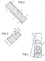
- This angle ⁇ is between 3 and 12 °, preferably between 8 and 12 °. In this In a special case, the angle ⁇ is 11 ° (see also FIG. 3).
- 1c shows the indexable insert according to FIG. 1a from the underside. Compared 1a and 1c that the secondary cutting edges 5a, 5b, 5c, 5d and main cutting edges 4a, 4b, 4c, 4d on both sides of the insert are each offset by 90 °, so that a main cutting edge 4a, 4b, 4c, 4d on one side an auxiliary cutting edge 5a, 5b, 5c, 5d on the other side opposite.
- the secondary cutting edges 5a, 5b, 5c, 5d provided on its outer edge with a flat support surface 7, which on the main edge 4a, 4b, 4c, 4d in the other side of the insert Relieved case.
- FIG. 2 shows a section along the line AA in FIG. 1c.
- Fig. 4 shows the view of a clamp holder with a clamping claw 8, the one inventive insert 9 fixed exciting.
- the rake angle is in this embodiment -8 ° and the angle of inclination -7 °.
- 5a-d show an indexable insert according to the invention in which the triangular surface 3 is divided by the diagonal D into two partial surfaces 3a, 3b.
- the two partial surfaces of the main cutting edge (4a, 4b, 4c, 4d) and the secondary cutting edge (5a, 5b, 5c, 5d) are inclined at right angles by an angle ⁇ to the center of symmetry E.
- 5d shows a corner of the cutting plate enlarged.
- Fig. 5b shows a section along the line AA of Fig. 5a
- Fig. 5c shows a section along the line BB of Fig. 5a.
- the angle ⁇ of the two inclinations is 3 °.
- other angles can also be used if this ensures sufficient chip evacuation.
Landscapes
- Engineering & Computer Science (AREA)
- Mechanical Engineering (AREA)
- Cutting Tools, Boring Holders, And Turrets (AREA)
- Processing Of Stones Or Stones Resemblance Materials (AREA)
- Milling Processes (AREA)
- Polishing Bodies And Polishing Tools (AREA)
Applications Claiming Priority (8)
| Application Number | Priority Date | Filing Date | Title |
|---|---|---|---|
| DE10005268 | 2000-02-05 | ||
| DE10005268 | 2000-02-05 | ||
| DE10022199 | 2000-05-06 | ||
| DE10022199 | 2000-05-06 | ||
| DE10036464 | 2000-07-25 | ||
| DE10036464 | 2000-07-25 | ||
| DE10041023 | 2000-08-22 | ||
| DE10041023A DE10041023A1 (de) | 2000-02-05 | 2000-08-22 | Schneidplatte |
Publications (3)
| Publication Number | Publication Date |
|---|---|
| EP1125660A2 true EP1125660A2 (fr) | 2001-08-22 |
| EP1125660A3 EP1125660A3 (fr) | 2002-06-26 |
| EP1125660B1 EP1125660B1 (fr) | 2006-11-08 |
Family
ID=27437766
Family Applications (1)
| Application Number | Title | Priority Date | Filing Date |
|---|---|---|---|
| EP01101033A Expired - Lifetime EP1125660B1 (fr) | 2000-02-05 | 2001-01-18 | Plaquette de coupe |
Country Status (5)
| Country | Link |
|---|---|
| US (1) | US6695550B2 (fr) |
| EP (1) | EP1125660B1 (fr) |
| AT (1) | ATE344705T1 (fr) |
| DE (1) | DE50111396D1 (fr) |
| ES (1) | ES2276719T3 (fr) |
Families Citing this family (5)
| Publication number | Priority date | Publication date | Assignee | Title |
|---|---|---|---|---|
| EP2446989B1 (fr) * | 2010-10-29 | 2016-12-14 | Seco Tools Ab | Insert de coupe de plongée axiale, outil de coupe de plongée axiale et méthode de coupe en plongée axiale |
| CN102744431B (zh) * | 2012-07-24 | 2014-01-22 | 哈尔滨理工大学 | 一种极端超重载条件下握型车铣复合专用刀片 |
| WO2020028663A1 (fr) * | 2018-08-02 | 2020-02-06 | Us Synthetic Corporation | Outil de coupe à inserts de diamant polycristallin, systèmes les incorporant et procédés associés |
| US11453065B2 (en) * | 2019-05-24 | 2022-09-27 | Iscar, Ltd. | Cutting insert having lower anti-slip recess, insert holder and cutting tool |
| JP6919824B2 (ja) * | 2020-01-15 | 2021-08-18 | 株式会社タンガロイ | 切削インサート及び該切削インサートを用いた旋削工具 |
Family Cites Families (11)
| Publication number | Priority date | Publication date | Assignee | Title |
|---|---|---|---|---|
| IL47571A (en) * | 1974-11-29 | 1978-12-17 | Kennametal Inc | Molded cutting insert |
| DE3136549A1 (de) * | 1981-09-15 | 1983-03-31 | Feldmühle AG, 4000 Düsseldorf | Schneidwerkzeug |
| GB2116082A (en) * | 1982-02-26 | 1983-09-21 | Gen Electric | Inserts for cutting tools |
| DE3303263C2 (de) * | 1983-02-01 | 1985-12-19 | Fried. Krupp Gmbh, 4300 Essen | Neuneckige Wendeschneidplatte |
| US4606679A (en) * | 1983-08-29 | 1986-08-19 | Gte Valeron Corporation | Cutting insert with chip control |
| US5032050A (en) * | 1987-09-04 | 1991-07-16 | Kennametal Inc. | On-edge cutting insert with chip control |
| DE4411475A1 (de) * | 1994-04-01 | 1995-10-05 | Walter Ag | Schneidplatte, insbesondere Wendeschneidplatte |
| DE4415425A1 (de) * | 1994-05-03 | 1995-11-09 | Krupp Widia Gmbh | Spanendes Werkzeug |
| SE509219C2 (sv) * | 1994-10-21 | 1998-12-21 | Sandvik Ab | Frässkär |
| DE19627990C5 (de) * | 1996-07-11 | 2004-07-01 | MAPAL Fabrik für Präzisionswerkzeuge Dr. Kress KG | Als Vieleck ausgebildete Schneidplatte |
| SE512253C2 (sv) * | 1997-06-30 | 2000-02-21 | Sandvik Ab | Vändskär |
-
2001
- 2001-01-18 ES ES01101033T patent/ES2276719T3/es not_active Expired - Lifetime
- 2001-01-18 EP EP01101033A patent/EP1125660B1/fr not_active Expired - Lifetime
- 2001-01-18 AT AT01101033T patent/ATE344705T1/de not_active IP Right Cessation
- 2001-01-18 DE DE50111396T patent/DE50111396D1/de not_active Expired - Fee Related
- 2001-02-05 US US09/775,661 patent/US6695550B2/en not_active Expired - Fee Related
Also Published As
| Publication number | Publication date |
|---|---|
| ATE344705T1 (de) | 2006-11-15 |
| EP1125660B1 (fr) | 2006-11-08 |
| ES2276719T3 (es) | 2007-07-01 |
| DE50111396D1 (de) | 2006-12-21 |
| EP1125660A3 (fr) | 2002-06-26 |
| US6695550B2 (en) | 2004-02-24 |
| US20020034425A1 (en) | 2002-03-21 |
Similar Documents
| Publication | Publication Date | Title |
|---|---|---|
| DE10085433B4 (de) | Schneideinsatz und Werkzeughaltervorrichtung dafür | |
| EP1536903B1 (fr) | Matrice de decoupage a deux cavites | |
| EP1879714B1 (fr) | Plaquette reversible | |
| DE69011437T2 (de) | Indexierbarer Schneideeinsatz. | |
| DE4324411A1 (de) | Sägeblatt für das Metallschneiden | |
| EP1309418B1 (fr) | Plaquette de coupe | |
| EP1462199A1 (fr) | Plaquette de coupe et outil de fraisage | |
| AT12630U1 (de) | Doppelseitiger schneideinsatz zum fräsen | |
| AT8743U1 (de) | Fräswerkzeug | |
| DE3714533A1 (de) | Fraeser mit schneideinsaetzen | |
| DE112007002652T5 (de) | Multifunktions-Schneidewerkzeug | |
| DE3856325T2 (de) | Schneideinsatz mit Spankontrolle | |
| DE68914163T2 (de) | Schneideinsatz mit spankontrolle. | |
| EP1213080B1 (fr) | Outil de forage | |
| DE2334547C3 (de) | Wendeschneidplatte | |
| DE10305854B4 (de) | Viereckiger Schneideinsatz für Fräser mit negativem Radialwinkel der Schneiden für das dreidimensionale Fräsen aus dem Vollen | |
| EP1125660B1 (fr) | Plaquette de coupe | |
| DE68909556T2 (de) | Fräser mit Schneideeinsätzen. | |
| DE19517311A1 (de) | Schneidplattenanordnung für Bohrwerkzeug | |
| DE3114104A1 (de) | Schneideinsatz zum gewindeschneiden | |
| CH645287A5 (de) | Wendeschneidplattenhalter. | |
| DE60016935T2 (de) | Methode zum spannen eines schneideinsatzes, schneideinsatz und schneidwerkzeug | |
| DE10041023A1 (de) | Schneidplatte | |
| DE2510960A1 (de) | Schneidplatte | |
| EP2420337A1 (fr) | Plaquette réversible servant à chanfreiner au moyen d'une tête de fraisage conique |
Legal Events
| Date | Code | Title | Description |
|---|---|---|---|
| PUAI | Public reference made under article 153(3) epc to a published international application that has entered the european phase |
Free format text: ORIGINAL CODE: 0009012 |
|
| AK | Designated contracting states |
Kind code of ref document: A2 Designated state(s): AT BE CH CY DE DK ES FI FR GB GR IE IT LI LU MC NL PT SE TR |
|
| AX | Request for extension of the european patent |
Free format text: AL;LT;LV;MK;RO;SI |
|
| PUAL | Search report despatched |
Free format text: ORIGINAL CODE: 0009013 |
|
| AK | Designated contracting states |
Kind code of ref document: A3 Designated state(s): AT BE CH CY DE DK ES FI FR GB GR IE IT LI LU MC NL PT SE TR |
|
| AX | Request for extension of the european patent |
Free format text: AL;LT;LV;MK;RO;SI |
|
| 17P | Request for examination filed |
Effective date: 20021227 |
|
| AKX | Designation fees paid |
Designated state(s): AT BE CH CY DE DK ES FI FR GB GR IE IT LI LU MC NL PT SE TR |
|
| GRAP | Despatch of communication of intention to grant a patent |
Free format text: ORIGINAL CODE: EPIDOSNIGR1 |
|
| GRAS | Grant fee paid |
Free format text: ORIGINAL CODE: EPIDOSNIGR3 |
|
| GRAA | (expected) grant |
Free format text: ORIGINAL CODE: 0009210 |
|
| AK | Designated contracting states |
Kind code of ref document: B1 Designated state(s): AT BE CH CY DE DK ES FI FR GB GR IE IT LI LU MC NL PT SE TR |
|
| PG25 | Lapsed in a contracting state [announced via postgrant information from national office to epo] |
Ref country code: NL Free format text: LAPSE BECAUSE OF FAILURE TO SUBMIT A TRANSLATION OF THE DESCRIPTION OR TO PAY THE FEE WITHIN THE PRESCRIBED TIME-LIMIT Effective date: 20061108 Ref country code: IE Free format text: LAPSE BECAUSE OF FAILURE TO SUBMIT A TRANSLATION OF THE DESCRIPTION OR TO PAY THE FEE WITHIN THE PRESCRIBED TIME-LIMIT Effective date: 20061108 Ref country code: FI Free format text: LAPSE BECAUSE OF FAILURE TO SUBMIT A TRANSLATION OF THE DESCRIPTION OR TO PAY THE FEE WITHIN THE PRESCRIBED TIME-LIMIT Effective date: 20061108 |
|
| REG | Reference to a national code |
Ref country code: GB Ref legal event code: FG4D Free format text: NOT ENGLISH |
|
| REG | Reference to a national code |
Ref country code: CH Ref legal event code: EP |
|
| REG | Reference to a national code |
Ref country code: IE Ref legal event code: FG4D Free format text: LANGUAGE OF EP DOCUMENT: GERMAN |
|
| REF | Corresponds to: |
Ref document number: 50111396 Country of ref document: DE Date of ref document: 20061221 Kind code of ref document: P |
|
| PG25 | Lapsed in a contracting state [announced via postgrant information from national office to epo] |
Ref country code: CH Free format text: LAPSE BECAUSE OF NON-PAYMENT OF DUE FEES Effective date: 20070131 Ref country code: MC Free format text: LAPSE BECAUSE OF NON-PAYMENT OF DUE FEES Effective date: 20070131 Ref country code: LI Free format text: LAPSE BECAUSE OF NON-PAYMENT OF DUE FEES Effective date: 20070131 |
|
| PG25 | Lapsed in a contracting state [announced via postgrant information from national office to epo] |
Ref country code: DK Free format text: LAPSE BECAUSE OF FAILURE TO SUBMIT A TRANSLATION OF THE DESCRIPTION OR TO PAY THE FEE WITHIN THE PRESCRIBED TIME-LIMIT Effective date: 20070208 |
|
| REG | Reference to a national code |
Ref country code: SE Ref legal event code: TRGR |
|
| GBT | Gb: translation of ep patent filed (gb section 77(6)(a)/1977) |
Effective date: 20070207 |
|
| PG25 | Lapsed in a contracting state [announced via postgrant information from national office to epo] |
Ref country code: PT Free format text: LAPSE BECAUSE OF FAILURE TO SUBMIT A TRANSLATION OF THE DESCRIPTION OR TO PAY THE FEE WITHIN THE PRESCRIBED TIME-LIMIT Effective date: 20070409 |
|
| NLV1 | Nl: lapsed or annulled due to failure to fulfill the requirements of art. 29p and 29m of the patents act | ||
| ET | Fr: translation filed | ||
| REG | Reference to a national code |
Ref country code: IE Ref legal event code: FD4D |
|
| REG | Reference to a national code |
Ref country code: ES Ref legal event code: FG2A Ref document number: 2276719 Country of ref document: ES Kind code of ref document: T3 |
|
| PLBE | No opposition filed within time limit |
Free format text: ORIGINAL CODE: 0009261 |
|
| REG | Reference to a national code |
Ref country code: CH Ref legal event code: PL |
|
| STAA | Information on the status of an ep patent application or granted ep patent |
Free format text: STATUS: NO OPPOSITION FILED WITHIN TIME LIMIT |
|
| 26N | No opposition filed |
Effective date: 20070809 |
|
| BERE | Be: lapsed |
Owner name: CERAMTEC A.G. INNOVATIVE CERAMIC ENGINEERING Effective date: 20070131 |
|
| PG25 | Lapsed in a contracting state [announced via postgrant information from national office to epo] |
Ref country code: BE Free format text: LAPSE BECAUSE OF NON-PAYMENT OF DUE FEES Effective date: 20070131 |
|
| PG25 | Lapsed in a contracting state [announced via postgrant information from national office to epo] |
Ref country code: GR Free format text: LAPSE BECAUSE OF FAILURE TO SUBMIT A TRANSLATION OF THE DESCRIPTION OR TO PAY THE FEE WITHIN THE PRESCRIBED TIME-LIMIT Effective date: 20070209 |
|
| PGFP | Annual fee paid to national office [announced via postgrant information from national office to epo] |
Ref country code: ES Payment date: 20080130 Year of fee payment: 8 |
|
| PGFP | Annual fee paid to national office [announced via postgrant information from national office to epo] |
Ref country code: GB Payment date: 20080124 Year of fee payment: 8 Ref country code: IT Payment date: 20080123 Year of fee payment: 8 Ref country code: SE Payment date: 20080114 Year of fee payment: 8 |
|
| PG25 | Lapsed in a contracting state [announced via postgrant information from national office to epo] |
Ref country code: AT Free format text: LAPSE BECAUSE OF NON-PAYMENT OF DUE FEES Effective date: 20070118 |
|
| PGFP | Annual fee paid to national office [announced via postgrant information from national office to epo] |
Ref country code: DE Payment date: 20080325 Year of fee payment: 8 Ref country code: FR Payment date: 20080111 Year of fee payment: 8 |
|
| PG25 | Lapsed in a contracting state [announced via postgrant information from national office to epo] |
Ref country code: LU Free format text: LAPSE BECAUSE OF NON-PAYMENT OF DUE FEES Effective date: 20070118 Ref country code: CY Free format text: LAPSE BECAUSE OF FAILURE TO SUBMIT A TRANSLATION OF THE DESCRIPTION OR TO PAY THE FEE WITHIN THE PRESCRIBED TIME-LIMIT Effective date: 20061108 |
|
| EUG | Se: european patent has lapsed | ||
| GBPC | Gb: european patent ceased through non-payment of renewal fee |
Effective date: 20090118 |
|
| PG25 | Lapsed in a contracting state [announced via postgrant information from national office to epo] |
Ref country code: TR Free format text: LAPSE BECAUSE OF FAILURE TO SUBMIT A TRANSLATION OF THE DESCRIPTION OR TO PAY THE FEE WITHIN THE PRESCRIBED TIME-LIMIT Effective date: 20061108 |
|
| PG25 | Lapsed in a contracting state [announced via postgrant information from national office to epo] |
Ref country code: DE Free format text: LAPSE BECAUSE OF NON-PAYMENT OF DUE FEES Effective date: 20090801 |
|
| REG | Reference to a national code |
Ref country code: FR Ref legal event code: ST Effective date: 20091030 |
|
| PG25 | Lapsed in a contracting state [announced via postgrant information from national office to epo] |
Ref country code: GB Free format text: LAPSE BECAUSE OF NON-PAYMENT OF DUE FEES Effective date: 20090118 |
|
| REG | Reference to a national code |
Ref country code: ES Ref legal event code: FD2A Effective date: 20090119 |
|
| PG25 | Lapsed in a contracting state [announced via postgrant information from national office to epo] |
Ref country code: FR Free format text: LAPSE BECAUSE OF NON-PAYMENT OF DUE FEES Effective date: 20090202 Ref country code: ES Free format text: LAPSE BECAUSE OF NON-PAYMENT OF DUE FEES Effective date: 20090119 |
|
| PG25 | Lapsed in a contracting state [announced via postgrant information from national office to epo] |
Ref country code: IT Free format text: LAPSE BECAUSE OF NON-PAYMENT OF DUE FEES Effective date: 20090118 |
|
| PG25 | Lapsed in a contracting state [announced via postgrant information from national office to epo] |
Ref country code: SE Free format text: LAPSE BECAUSE OF NON-PAYMENT OF DUE FEES Effective date: 20090119 |