EP1125660B1 - Plaquette de coupe - Google Patents
Plaquette de coupe Download PDFInfo
- Publication number
- EP1125660B1 EP1125660B1 EP01101033A EP01101033A EP1125660B1 EP 1125660 B1 EP1125660 B1 EP 1125660B1 EP 01101033 A EP01101033 A EP 01101033A EP 01101033 A EP01101033 A EP 01101033A EP 1125660 B1 EP1125660 B1 EP 1125660B1
- Authority
- EP
- European Patent Office
- Prior art keywords
- cutting plate
- reversible
- cutting
- plate according
- cutting edge
- Prior art date
- Legal status (The legal status is an assumption and is not a legal conclusion. Google has not performed a legal analysis and makes no representation as to the accuracy of the status listed.)
- Expired - Lifetime
Links
- 230000002441 reversible effect Effects 0.000 claims abstract description 27
- 239000000463 material Substances 0.000 claims abstract description 7
- 238000003754 machining Methods 0.000 claims abstract description 5
- 229910010293 ceramic material Inorganic materials 0.000 claims abstract description 3
- 210000000078 claw Anatomy 0.000 claims description 5
- 239000000919 ceramic Substances 0.000 description 2
- 229910001018 Cast iron Inorganic materials 0.000 description 1
- 238000005299 abrasion Methods 0.000 description 1
- 238000005266 casting Methods 0.000 description 1
- 229910052574 oxide ceramic Inorganic materials 0.000 description 1
- TWNQGVIAIRXVLR-UHFFFAOYSA-N oxo(oxoalumanyloxy)alumane Chemical compound O=[Al]O[Al]=O TWNQGVIAIRXVLR-UHFFFAOYSA-N 0.000 description 1
- RVTZCBVAJQQJTK-UHFFFAOYSA-N oxygen(2-);zirconium(4+) Chemical compound [O-2].[O-2].[Zr+4] RVTZCBVAJQQJTK-UHFFFAOYSA-N 0.000 description 1
- 229910001928 zirconium oxide Inorganic materials 0.000 description 1
Images

Classifications
-
- B—PERFORMING OPERATIONS; TRANSPORTING
- B23—MACHINE TOOLS; METAL-WORKING NOT OTHERWISE PROVIDED FOR
- B23B—TURNING; BORING
- B23B27/00—Tools for turning or boring machines; Tools of a similar kind in general; Accessories therefor
- B23B27/14—Cutting tools of which the bits or tips or cutting inserts are of special material
- B23B27/16—Cutting tools of which the bits or tips or cutting inserts are of special material with exchangeable cutting bits or cutting inserts, e.g. able to be clamped
- B23B27/1644—Cutting tools of which the bits or tips or cutting inserts are of special material with exchangeable cutting bits or cutting inserts, e.g. able to be clamped with plate-like cutting inserts of special shape clamped by a clamping member acting almost perpendicularly on the chip-forming plane and at the same time upon the wall of a hole in the cutting insert
- B23B27/1651—Cutting tools of which the bits or tips or cutting inserts are of special material with exchangeable cutting bits or cutting inserts, e.g. able to be clamped with plate-like cutting inserts of special shape clamped by a clamping member acting almost perpendicularly on the chip-forming plane and at the same time upon the wall of a hole in the cutting insert characterised by having a special shape
-
- B—PERFORMING OPERATIONS; TRANSPORTING
- B23—MACHINE TOOLS; METAL-WORKING NOT OTHERWISE PROVIDED FOR
- B23B—TURNING; BORING
- B23B2200/00—Details of cutting inserts
- B23B2200/08—Rake or top surfaces
- B23B2200/086—Rake or top surfaces with one or more grooves
- B23B2200/087—Rake or top surfaces with one or more grooves for chip breaking
-
- B—PERFORMING OPERATIONS; TRANSPORTING
- B23—MACHINE TOOLS; METAL-WORKING NOT OTHERWISE PROVIDED FOR
- B23B—TURNING; BORING
- B23B2200/00—Details of cutting inserts
- B23B2200/08—Rake or top surfaces
- B23B2200/086—Rake or top surfaces with one or more grooves
- B23B2200/088—Rake or top surfaces with one or more grooves for clamping
-
- Y—GENERAL TAGGING OF NEW TECHNOLOGICAL DEVELOPMENTS; GENERAL TAGGING OF CROSS-SECTIONAL TECHNOLOGIES SPANNING OVER SEVERAL SECTIONS OF THE IPC; TECHNICAL SUBJECTS COVERED BY FORMER USPC CROSS-REFERENCE ART COLLECTIONS [XRACs] AND DIGESTS
- Y10—TECHNICAL SUBJECTS COVERED BY FORMER USPC
- Y10T—TECHNICAL SUBJECTS COVERED BY FORMER US CLASSIFICATION
- Y10T407/00—Cutters, for shaping
- Y10T407/23—Cutters, for shaping including tool having plural alternatively usable cutting edges
- Y10T407/235—Cutters, for shaping including tool having plural alternatively usable cutting edges with integral chip breaker, guide or deflector
-
- Y—GENERAL TAGGING OF NEW TECHNOLOGICAL DEVELOPMENTS; GENERAL TAGGING OF CROSS-SECTIONAL TECHNOLOGIES SPANNING OVER SEVERAL SECTIONS OF THE IPC; TECHNICAL SUBJECTS COVERED BY FORMER USPC CROSS-REFERENCE ART COLLECTIONS [XRACs] AND DIGESTS
- Y10—TECHNICAL SUBJECTS COVERED BY FORMER USPC
- Y10T—TECHNICAL SUBJECTS COVERED BY FORMER US CLASSIFICATION
- Y10T407/00—Cutters, for shaping
- Y10T407/24—Cutters, for shaping with chip breaker, guide or deflector
- Y10T407/245—Cutters, for shaping with chip breaker, guide or deflector comprising concave surface in cutting face of tool
-
- Y—GENERAL TAGGING OF NEW TECHNOLOGICAL DEVELOPMENTS; GENERAL TAGGING OF CROSS-SECTIONAL TECHNOLOGIES SPANNING OVER SEVERAL SECTIONS OF THE IPC; TECHNICAL SUBJECTS COVERED BY FORMER USPC CROSS-REFERENCE ART COLLECTIONS [XRACs] AND DIGESTS
- Y10—TECHNICAL SUBJECTS COVERED BY FORMER USPC
- Y10T—TECHNICAL SUBJECTS COVERED BY FORMER US CLASSIFICATION
- Y10T407/00—Cutters, for shaping
- Y10T407/27—Cutters, for shaping comprising tool of specific chemical composition
Definitions
- the invention relates to an indexable insert made of ceramic for clamping in a cutting tool for machining cast materials according to the preamble of claim 1.
- a ceramic insert for clamping in a cutting tool for machining cast materials, in particular cast iron is known.
- the cutting plate includes on its upper side a star-shaped trough with four teeth for engagement of a clamping claw or a clamping finger of the cutting tool, wherein each corner of the insert has a minor cutting edge and a main cutting edge.
- the cutting tool consists of a clamping holder and a replaceable insert to be inserted into the clamping holder.
- the cutting plate is the part that engages the workpiece and this machined.
- the cutting plate must therefore be made of extremely hard material, which has the lowest possible abrasion when machining metallic workpieces.
- oxide-ceramic materials such as aluminum oxide or zirconium oxide. Such ceramic materials have a very high hardness and compressive strength, but only a limited tensile strength.
- the invention has for its object to improve an indexable insert according to the preamble of claim 1 so that the cast chips are removed from the cutting edge and thereby the cutting edge is relieved.
- this object is achieved in that the corners are ground in about 1 ⁇ 4 of the diagonal plane, pressed or injected and so on Form triangular surface or chip forming step and the triangular surface has at least one inclination.
- the castings are removed from the cutting edge corner to the center of the insert and thereby relieve the cutting edge. It is created by these measures a positive chip forming stage.
- the triangular surface is inclined by the secondary cutting edge in the direction of the side center at an angle ⁇ .
- An alternative embodiment is characterized in that the triangular surface is divided by the diagonal into two partial surfaces and at least one partial surface of the main cutting edge or the minor cutting edge is inclined at right angles through an angle ⁇ to the symmetry center.
- both partial surfaces are inclined towards the center of symmetry.
- Symmetry center is understood as the intersection of the diagonals of the cutting plate with the hypotenuse of the triangular surface.
- the angle ⁇ is preferably between 3 and 12 °. With a plate thickness d of 5 mm, z. B. a preferred maximum reduction x of 1.5 mm.
- the secondary cutting edges are preferably provided at their outer edge with a flat bearing surface which relieves the main cutting edge located on the other side when turning the cutting plate.
- the cutting plate is formed as an indexable insert, wherein the minor cutting edges and main cutting edges are arranged offset on both sides by 90 °, so that a main cutting edge on one side of a secondary cutting edge on the other side and vice versa , The main cutting edge is thus supported on the other side by the planar contact surface along the minor cutting edge.
- the planar contact surface preferably extends over the entire length of the minor cutting edge and has a width of preferably 1 mm.
- Each corner is divided into two triangles by the corresponding diagonal.
- the main cutting edge When viewed topically on an upper side, the main cutting edge is arranged in the clockwise direction in front of the diagonal and the secondary cutting edge is arranged behind the diagonal. This applies to clockwise cutting inserts. For left-hand cutting inserts this is the reverse case.
- the cutting plate For attachment of the cutting plate in the cutting tool, the cutting plate in a preferred embodiment, a star-shaped trough with four teeth, wherein the tines are each aligned with the center of a longitudinal side. In the trough engages a clamping finger of a clamping claw of the cutting tool so that it is fixed in position.
- all four corners of an upper side of the cutting plate can be used for cutting.
- an identical trough is arranged, so that a total of eight corners are available for cutting.
- a hole for engagement of a clamping bolt of the cutting tool in the cutting plate is arranged instead of the trough.
- the indexable insert can also have a smooth surface except the inventively formed corners. These inserts are also referred to as smooth inserts.
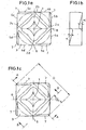
- FIG. 1a shows a side of an indexable insert with a star-shaped depression 1 with four points 2a, 2b, 2c, 2d which are each aligned with the middle 6 of a longitudinal side.
- the trough 1 is shaped such that a clamping finger of a clamping claw of a cutting tool fixes the indexable insert in exciting contact in the cutting tool (see FIG. 4).
- the corners of the indexable insert are respectively ground or pressed and form a chip forming step in the form and shape of a triangular surface 3.
- the main cutting edges are denoted by the reference numerals 4a, 4b, 4c, 4d and the minor cutting edges by the reference numerals 5a, 5b, 5c, 5d. It is assumed here by a clockwise plate.
- the chip forming step or triangular surface 3 extends approximately 1 ⁇ 4 of the length of the diagonal D of the cutting insert into the plate (see FIG. 1c).
- the chip forming stage 3 forms a triangular surface which slopes from the secondary cutting edge 5a, 5b, 5c, 5d in the direction of the center of the side 6 at an angle ⁇ .
- This angle ⁇ is between 3 and 12 °, preferably between 8 and 12 °. In this particular case, the angle ⁇ is 11 ° (see also Fig. 3).
- Fig. 1c shows the indexable insert of FIG. 1a from the bottom.
- the secondary cutting edges 5a, 5b, 5c, 5d and main cutting edges 4a, 4b, 4c, 4d are each offset by 90 ° on the two sides of the indexable insert so that a main cutting edge 4a , 4b, 4c, 4d on the one side a secondary cutting edge 5a, 5b, 5c, 5d on the other side opposite.
- the minor cutting edges 5a, 5b, 5c, 5d are provided at their outer edge with a flat bearing surface 7, which is the main cutting edge 4a, 4b, 4c, 4d located on the other side of the cutting insert relieved.
- Figure 2 shows a section along the line A - A in Fig. 1c.
- Fig. 4 shows the view of a clamping holder with a clamping claw 8, which fixes an indexable insert 9 according to the invention exciting.
- the clamping angle in this embodiment is -8 ° and the inclination angle is -7 °.
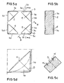
- FIG. 5a-d show an indexable insert according to the invention, in which the triangular surface 3 is divided by the diagonal D into two partial surfaces 3a, 3b.
- the two partial surfaces of the main cutting edge (4a, 4b, 4c, 4d) and the secondary cutting edge (5a, 5b, 5c, 5d) are inclined at right angles by an angle ⁇ to the center of symmetry E.
- Fig. 5d shows a corner of the cutting plate enlarged.
- 5b shows a section along the line AA of FIG. 5a
- FIG. 5c shows a section along the line BB of FIG. 5a.
- the angle ⁇ of the two slopes is in this case at 3 °. However, other angles can be used, if this ensures sufficient chip removal.
Landscapes
- Engineering & Computer Science (AREA)
- Mechanical Engineering (AREA)
- Cutting Tools, Boring Holders, And Turrets (AREA)
- Polishing Bodies And Polishing Tools (AREA)
- Processing Of Stones Or Stones Resemblance Materials (AREA)
- Milling Processes (AREA)
Claims (15)
- Plaquette de coupe amovible (9) en céramique destinée à être serrée dans un outil de coupe, en vue de l'usinage par enlèvement de copeaux de matériaux moulés, chaque angle de la plaquette de coupe amovible (9) présentant une arête de coupe secondaire (5a, 5b, 5c, 5d) et une arête de coupe principale (4a, 4b, 4c, 4d), caractérisée par le fait que les angles de la plaquette de coupe amovible (9) sont réalisés dans environ ¼ du plan diagonal (D), par rectification, compression ou injection, et forment une surface triangulaire (3) et que cette surface triangulaire (3) présente au moins une inclinaison.
- Plaquette de coupe amovible selon la revendication 1, caractérisée par le fait que la surface triangulaire (3) est inclinée sous un angle α, depuis l'arête de coupe secondaire (5a, 5b, 5c, 5d) en direction du milieu de côté (6).
- Plaquette de coupe amovible selon la revendication 1, caractérisée par le fait que la surface triangulaire (3) est divisée en deux surfaces partielles (3a, 3b) par la diagonale (D), et au moins une surface partielle (3a, 3b) est inclinée sous un angle α, perpendiculairement depuis l'arête de coupe principale (4a, 4b, 4c, 4d) ou l'arête de coupe secondaire (5a, 5b, 5c, 5d) en direction du milieu de symétrie (E).
- Plaquette de coupe amovible selon la revendication 3, caractérisée par le fait que les deux surfaces partielles (3a, 3b) sont inclinées en direction du milieu de symétrie (E).
- Plaquette de coupe amovible selon une des revendications 1 à 5, caractérisée par le fait que l'angle α est compris entre 3° et 12°.
- Plaquette de coupe amovible selon une des revendications 1 à 5, caractérisée par le fait que les arêtes de coupe secondaires (5a, 5b, 5c, 5d) et les arêtes de coupe principales (4a, 4b, 4c, 4d) sont décalées de 90° sur les deux faces de la plaquette de coupe amovible (9), de sorte qu'une arête de coupe principale (4a, 4b, 4c, 4d) située sur une face est en vis-à-vis d'une arête de coupe secondaire (5a, 5b, 5c, 5d) située sur l'autre face et inversement.
- Plaquette de coupe amovible selon une des revendications 1 à 6, caractérisée par le fait que les arêtes de coupe secondaires (5a, 5b, 5c, 5d) sont pourvues d'une surface d'appui plane (7) sur leur bord extérieur.
- Plaquette de coupe amovible selon la revendication 7, caractérisée par le fait que la surface d'appui plane (7) s'étend sur toute la longueur de l'arête de coupe secondaire (5a, 5b, 5c, 5d).
- Plaquette de coupe amovible selon la revendication 7 ou 8, caractérisée par le fait que la surface d'appui plane (7) s'étend sur toute la longueur de l'arête de coupe secondaire (5a, 5b, 5c, 5d).
- Plaquette de coupe amovible selon une des revendications 1 à 9, caractérisée par le fait que pour des plaquettes de coupe (9) tournant à gauche, dans une vue de dessus d'une face de la plaquette de coupe amovible (9), dans le sens des aiguilles d'une montre, l'arête de coupe principale (4a, 4b, 4c, 4d) est disposée avant la diagonale (D) et l'arête de coupe secondaire (5a, 5b, 5c, 5d) est disposée après la diagonale (D), et inversement pour des plaquettes de coupe tournant à droite.
- Plaquette de coupe amovible selon une des revendications 1 à 10, caractérisée par le fait qu'un creux (1) est aménagé sur chaque face de la plaquette de coupe amovible (9), en vue de l'entrée en prise d'une griffe de serrage (8).
- Plaquette de coupe amovible selon la revendication 11, caractérisée par le fait que le creux (1) est conformé en étoile à quatre branches (2a, 2b, 2c, 2d).
- Plaquette de coupe amovible selon la revendication 12, caractérisée par le fait que les branches (2a, 2b, 2c, 2d) du creux (1) sont dirigées vers le milieu (6) des côtés.
- Plaquette de coupe amovible selon une des revendications 1 à 10, caractérisée par le fait que la plaquette de coupe amovible (9) comporte un trou pour l'entrée en prise d'une broche de serrage de l'outil de coupe.
- Plaquette de coupe amovible selon une des revendications 1 à 10, caractérisée par le fait qu'en dehors des angles agencés conformément à l'invention, la plaquette de coupe amovible (9) présente une surface lisse.
Applications Claiming Priority (8)
| Application Number | Priority Date | Filing Date | Title |
|---|---|---|---|
| DE10005268 | 2000-02-05 | ||
| DE10005268 | 2000-02-05 | ||
| DE10022199 | 2000-05-06 | ||
| DE10022199 | 2000-05-06 | ||
| DE10036464 | 2000-07-25 | ||
| DE10036464 | 2000-07-25 | ||
| DE10041023A DE10041023A1 (de) | 2000-02-05 | 2000-08-22 | Schneidplatte |
| DE10041023 | 2000-08-22 |
Publications (3)
| Publication Number | Publication Date |
|---|---|
| EP1125660A2 EP1125660A2 (fr) | 2001-08-22 |
| EP1125660A3 EP1125660A3 (fr) | 2002-06-26 |
| EP1125660B1 true EP1125660B1 (fr) | 2006-11-08 |
Family
ID=27437766
Family Applications (1)
| Application Number | Title | Priority Date | Filing Date |
|---|---|---|---|
| EP01101033A Expired - Lifetime EP1125660B1 (fr) | 2000-02-05 | 2001-01-18 | Plaquette de coupe |
Country Status (5)
| Country | Link |
|---|---|
| US (1) | US6695550B2 (fr) |
| EP (1) | EP1125660B1 (fr) |
| AT (1) | ATE344705T1 (fr) |
| DE (1) | DE50111396D1 (fr) |
| ES (1) | ES2276719T3 (fr) |
Families Citing this family (5)
| Publication number | Priority date | Publication date | Assignee | Title |
|---|---|---|---|---|
| EP2446989B1 (fr) * | 2010-10-29 | 2016-12-14 | Seco Tools Ab | Insert de coupe de plongée axiale, outil de coupe de plongée axiale et méthode de coupe en plongée axiale |
| CN102744431B (zh) * | 2012-07-24 | 2014-01-22 | 哈尔滨理工大学 | 一种极端超重载条件下握型车铣复合专用刀片 |
| ES3034079T3 (en) * | 2018-08-02 | 2025-08-12 | Us Synthetic Corp | Cutting tool with pcd inserts, systems incorporating same and related methods |
| US11453065B2 (en) * | 2019-05-24 | 2022-09-27 | Iscar, Ltd. | Cutting insert having lower anti-slip recess, insert holder and cutting tool |
| JP6919824B2 (ja) * | 2020-01-15 | 2021-08-18 | 株式会社タンガロイ | 切削インサート及び該切削インサートを用いた旋削工具 |
Family Cites Families (11)
| Publication number | Priority date | Publication date | Assignee | Title |
|---|---|---|---|---|
| IL47571A (en) * | 1974-11-29 | 1978-12-17 | Kennametal Inc | Molded cutting insert |
| DE3136549A1 (de) * | 1981-09-15 | 1983-03-31 | Feldmühle AG, 4000 Düsseldorf | Schneidwerkzeug |
| GB2116082A (en) * | 1982-02-26 | 1983-09-21 | Gen Electric | Inserts for cutting tools |
| DE3303263C2 (de) * | 1983-02-01 | 1985-12-19 | Fried. Krupp Gmbh, 4300 Essen | Neuneckige Wendeschneidplatte |
| US4606679A (en) * | 1983-08-29 | 1986-08-19 | Gte Valeron Corporation | Cutting insert with chip control |
| US5032050A (en) * | 1987-09-04 | 1991-07-16 | Kennametal Inc. | On-edge cutting insert with chip control |
| DE4411475A1 (de) * | 1994-04-01 | 1995-10-05 | Walter Ag | Schneidplatte, insbesondere Wendeschneidplatte |
| DE4415425A1 (de) * | 1994-05-03 | 1995-11-09 | Krupp Widia Gmbh | Spanendes Werkzeug |
| SE509219C2 (sv) * | 1994-10-21 | 1998-12-21 | Sandvik Ab | Frässkär |
| DE19627990C5 (de) * | 1996-07-11 | 2004-07-01 | MAPAL Fabrik für Präzisionswerkzeuge Dr. Kress KG | Als Vieleck ausgebildete Schneidplatte |
| SE512253C2 (sv) * | 1997-06-30 | 2000-02-21 | Sandvik Ab | Vändskär |
-
2001
- 2001-01-18 AT AT01101033T patent/ATE344705T1/de not_active IP Right Cessation
- 2001-01-18 DE DE50111396T patent/DE50111396D1/de not_active Expired - Fee Related
- 2001-01-18 ES ES01101033T patent/ES2276719T3/es not_active Expired - Lifetime
- 2001-01-18 EP EP01101033A patent/EP1125660B1/fr not_active Expired - Lifetime
- 2001-02-05 US US09/775,661 patent/US6695550B2/en not_active Expired - Fee Related
Also Published As
| Publication number | Publication date |
|---|---|
| ATE344705T1 (de) | 2006-11-15 |
| DE50111396D1 (de) | 2006-12-21 |
| EP1125660A3 (fr) | 2002-06-26 |
| EP1125660A2 (fr) | 2001-08-22 |
| ES2276719T3 (es) | 2007-07-01 |
| US6695550B2 (en) | 2004-02-24 |
| US20020034425A1 (en) | 2002-03-21 |
Similar Documents
| Publication | Publication Date | Title |
|---|---|---|
| DE10085433B4 (de) | Schneideinsatz und Werkzeughaltervorrichtung dafür | |
| DE112015006941B4 (de) | Schneidplatte und Wende-Drehschneidwerkzeug | |
| EP1879714B1 (fr) | Plaquette reversible | |
| EP1536903B1 (fr) | Matrice de decoupage a deux cavites | |
| EP0958085B1 (fr) | Plaquette de coupe et outil de fraisage | |
| EP1599307B1 (fr) | Assemblage d'une tête de fraisage et d'une plaquette indexable servant à chanfreiner | |
| AT12630U1 (de) | Doppelseitiger schneideinsatz zum fräsen | |
| EP1309418B1 (fr) | Plaquette de coupe | |
| DE3714533A1 (de) | Fraeser mit schneideinsaetzen | |
| DE112007002652T5 (de) | Multifunktions-Schneidewerkzeug | |
| DE2734095C2 (de) | Schneidwerkzeug zum Schälen auf einer Drehbank | |
| DE102019128697A1 (de) | Drehwerkzeug | |
| EP1213080B1 (fr) | Outil de forage | |
| DE19517311A1 (de) | Schneidplattenanordnung für Bohrwerkzeug | |
| DE2637757A1 (de) | Prismenfoermige wendeschneidplatte | |
| DE2334547B2 (de) | Wendeschneidplatte | |
| DE1552544A1 (de) | Als Wendeschneidplatte ausgebildetes,vorzugsweise aus Hartmetall bestehendes Schneidelement zur Bestueckung von rundlaufenden,mit Spanneinrichtungen ausgeruesteten Werkzeugen,insbesondere fuer die Metallbearbeitung sowie mit diesen Wendeschneidplatten bestueckte Werkzeuge | |
| DE19704931C1 (de) | Schneideinsatz und Fräswerkzeug | |
| EP0804986B1 (fr) | Elément de coupe | |
| EP1125660A2 (fr) | Plaquette de coupe | |
| DE3114104A1 (de) | Schneideinsatz zum gewindeschneiden | |
| DE60016935T2 (de) | Methode zum spannen eines schneideinsatzes, schneideinsatz und schneidwerkzeug | |
| EP2420337B1 (fr) | Plaquette réversible servant à chanfreiner, et combinaison d'une tête de fraisage conique ou cylindrique et d'une plaquette réversible servant à chanfreiner | |
| DE10041023A1 (de) | Schneidplatte | |
| DE3807165A1 (de) | Umstellbarer schneideinsatz |
Legal Events
| Date | Code | Title | Description |
|---|---|---|---|
| PUAI | Public reference made under article 153(3) epc to a published international application that has entered the european phase |
Free format text: ORIGINAL CODE: 0009012 |
|
| AK | Designated contracting states |
Kind code of ref document: A2 Designated state(s): AT BE CH CY DE DK ES FI FR GB GR IE IT LI LU MC NL PT SE TR |
|
| AX | Request for extension of the european patent |
Free format text: AL;LT;LV;MK;RO;SI |
|
| PUAL | Search report despatched |
Free format text: ORIGINAL CODE: 0009013 |
|
| AK | Designated contracting states |
Kind code of ref document: A3 Designated state(s): AT BE CH CY DE DK ES FI FR GB GR IE IT LI LU MC NL PT SE TR |
|
| AX | Request for extension of the european patent |
Free format text: AL;LT;LV;MK;RO;SI |
|
| 17P | Request for examination filed |
Effective date: 20021227 |
|
| AKX | Designation fees paid |
Designated state(s): AT BE CH CY DE DK ES FI FR GB GR IE IT LI LU MC NL PT SE TR |
|
| GRAP | Despatch of communication of intention to grant a patent |
Free format text: ORIGINAL CODE: EPIDOSNIGR1 |
|
| GRAS | Grant fee paid |
Free format text: ORIGINAL CODE: EPIDOSNIGR3 |
|
| GRAA | (expected) grant |
Free format text: ORIGINAL CODE: 0009210 |
|
| AK | Designated contracting states |
Kind code of ref document: B1 Designated state(s): AT BE CH CY DE DK ES FI FR GB GR IE IT LI LU MC NL PT SE TR |
|
| PG25 | Lapsed in a contracting state [announced via postgrant information from national office to epo] |
Ref country code: NL Free format text: LAPSE BECAUSE OF FAILURE TO SUBMIT A TRANSLATION OF THE DESCRIPTION OR TO PAY THE FEE WITHIN THE PRESCRIBED TIME-LIMIT Effective date: 20061108 Ref country code: IE Free format text: LAPSE BECAUSE OF FAILURE TO SUBMIT A TRANSLATION OF THE DESCRIPTION OR TO PAY THE FEE WITHIN THE PRESCRIBED TIME-LIMIT Effective date: 20061108 Ref country code: FI Free format text: LAPSE BECAUSE OF FAILURE TO SUBMIT A TRANSLATION OF THE DESCRIPTION OR TO PAY THE FEE WITHIN THE PRESCRIBED TIME-LIMIT Effective date: 20061108 |
|
| REG | Reference to a national code |
Ref country code: GB Ref legal event code: FG4D Free format text: NOT ENGLISH |
|
| REG | Reference to a national code |
Ref country code: CH Ref legal event code: EP |
|
| REG | Reference to a national code |
Ref country code: IE Ref legal event code: FG4D Free format text: LANGUAGE OF EP DOCUMENT: GERMAN |
|
| REF | Corresponds to: |
Ref document number: 50111396 Country of ref document: DE Date of ref document: 20061221 Kind code of ref document: P |
|
| PG25 | Lapsed in a contracting state [announced via postgrant information from national office to epo] |
Ref country code: CH Free format text: LAPSE BECAUSE OF NON-PAYMENT OF DUE FEES Effective date: 20070131 Ref country code: MC Free format text: LAPSE BECAUSE OF NON-PAYMENT OF DUE FEES Effective date: 20070131 Ref country code: LI Free format text: LAPSE BECAUSE OF NON-PAYMENT OF DUE FEES Effective date: 20070131 |
|
| PG25 | Lapsed in a contracting state [announced via postgrant information from national office to epo] |
Ref country code: DK Free format text: LAPSE BECAUSE OF FAILURE TO SUBMIT A TRANSLATION OF THE DESCRIPTION OR TO PAY THE FEE WITHIN THE PRESCRIBED TIME-LIMIT Effective date: 20070208 |
|
| REG | Reference to a national code |
Ref country code: SE Ref legal event code: TRGR |
|
| GBT | Gb: translation of ep patent filed (gb section 77(6)(a)/1977) |
Effective date: 20070207 |
|
| PG25 | Lapsed in a contracting state [announced via postgrant information from national office to epo] |
Ref country code: PT Free format text: LAPSE BECAUSE OF FAILURE TO SUBMIT A TRANSLATION OF THE DESCRIPTION OR TO PAY THE FEE WITHIN THE PRESCRIBED TIME-LIMIT Effective date: 20070409 |
|
| NLV1 | Nl: lapsed or annulled due to failure to fulfill the requirements of art. 29p and 29m of the patents act | ||
| ET | Fr: translation filed | ||
| REG | Reference to a national code |
Ref country code: IE Ref legal event code: FD4D |
|
| REG | Reference to a national code |
Ref country code: ES Ref legal event code: FG2A Ref document number: 2276719 Country of ref document: ES Kind code of ref document: T3 |
|
| PLBE | No opposition filed within time limit |
Free format text: ORIGINAL CODE: 0009261 |
|
| REG | Reference to a national code |
Ref country code: CH Ref legal event code: PL |
|
| STAA | Information on the status of an ep patent application or granted ep patent |
Free format text: STATUS: NO OPPOSITION FILED WITHIN TIME LIMIT |
|
| 26N | No opposition filed |
Effective date: 20070809 |
|
| BERE | Be: lapsed |
Owner name: CERAMTEC A.G. INNOVATIVE CERAMIC ENGINEERING Effective date: 20070131 |
|
| PG25 | Lapsed in a contracting state [announced via postgrant information from national office to epo] |
Ref country code: BE Free format text: LAPSE BECAUSE OF NON-PAYMENT OF DUE FEES Effective date: 20070131 |
|
| PG25 | Lapsed in a contracting state [announced via postgrant information from national office to epo] |
Ref country code: GR Free format text: LAPSE BECAUSE OF FAILURE TO SUBMIT A TRANSLATION OF THE DESCRIPTION OR TO PAY THE FEE WITHIN THE PRESCRIBED TIME-LIMIT Effective date: 20070209 |
|
| PGFP | Annual fee paid to national office [announced via postgrant information from national office to epo] |
Ref country code: ES Payment date: 20080130 Year of fee payment: 8 |
|
| PGFP | Annual fee paid to national office [announced via postgrant information from national office to epo] |
Ref country code: GB Payment date: 20080124 Year of fee payment: 8 Ref country code: IT Payment date: 20080123 Year of fee payment: 8 Ref country code: SE Payment date: 20080114 Year of fee payment: 8 |
|
| PG25 | Lapsed in a contracting state [announced via postgrant information from national office to epo] |
Ref country code: AT Free format text: LAPSE BECAUSE OF NON-PAYMENT OF DUE FEES Effective date: 20070118 |
|
| PGFP | Annual fee paid to national office [announced via postgrant information from national office to epo] |
Ref country code: DE Payment date: 20080325 Year of fee payment: 8 Ref country code: FR Payment date: 20080111 Year of fee payment: 8 |
|
| PG25 | Lapsed in a contracting state [announced via postgrant information from national office to epo] |
Ref country code: LU Free format text: LAPSE BECAUSE OF NON-PAYMENT OF DUE FEES Effective date: 20070118 Ref country code: CY Free format text: LAPSE BECAUSE OF FAILURE TO SUBMIT A TRANSLATION OF THE DESCRIPTION OR TO PAY THE FEE WITHIN THE PRESCRIBED TIME-LIMIT Effective date: 20061108 |
|
| EUG | Se: european patent has lapsed | ||
| GBPC | Gb: european patent ceased through non-payment of renewal fee |
Effective date: 20090118 |
|
| PG25 | Lapsed in a contracting state [announced via postgrant information from national office to epo] |
Ref country code: TR Free format text: LAPSE BECAUSE OF FAILURE TO SUBMIT A TRANSLATION OF THE DESCRIPTION OR TO PAY THE FEE WITHIN THE PRESCRIBED TIME-LIMIT Effective date: 20061108 |
|
| PG25 | Lapsed in a contracting state [announced via postgrant information from national office to epo] |
Ref country code: DE Free format text: LAPSE BECAUSE OF NON-PAYMENT OF DUE FEES Effective date: 20090801 |
|
| REG | Reference to a national code |
Ref country code: FR Ref legal event code: ST Effective date: 20091030 |
|
| PG25 | Lapsed in a contracting state [announced via postgrant information from national office to epo] |
Ref country code: GB Free format text: LAPSE BECAUSE OF NON-PAYMENT OF DUE FEES Effective date: 20090118 |
|
| REG | Reference to a national code |
Ref country code: ES Ref legal event code: FD2A Effective date: 20090119 |
|
| PG25 | Lapsed in a contracting state [announced via postgrant information from national office to epo] |
Ref country code: FR Free format text: LAPSE BECAUSE OF NON-PAYMENT OF DUE FEES Effective date: 20090202 Ref country code: ES Free format text: LAPSE BECAUSE OF NON-PAYMENT OF DUE FEES Effective date: 20090119 |
|
| PG25 | Lapsed in a contracting state [announced via postgrant information from national office to epo] |
Ref country code: IT Free format text: LAPSE BECAUSE OF NON-PAYMENT OF DUE FEES Effective date: 20090118 |
|
| PG25 | Lapsed in a contracting state [announced via postgrant information from national office to epo] |
Ref country code: SE Free format text: LAPSE BECAUSE OF NON-PAYMENT OF DUE FEES Effective date: 20090119 |