EP1125818A1 - Mobile Plattform - Google Patents
Mobile Plattform Download PDFInfo
- Publication number
- EP1125818A1 EP1125818A1 EP00311383A EP00311383A EP1125818A1 EP 1125818 A1 EP1125818 A1 EP 1125818A1 EP 00311383 A EP00311383 A EP 00311383A EP 00311383 A EP00311383 A EP 00311383A EP 1125818 A1 EP1125818 A1 EP 1125818A1
- Authority
- EP
- European Patent Office
- Prior art keywords
- platform
- assembly
- connecting means
- connecting member
- assemblies
- Prior art date
- Legal status (The legal status is an assumption and is not a legal conclusion. Google has not performed a legal analysis and makes no representation as to the accuracy of the status listed.)
- Granted
Links
Images


Classifications
-
- B—PERFORMING OPERATIONS; TRANSPORTING
- B60—VEHICLES IN GENERAL
- B60D—VEHICLE CONNECTIONS
- B60D1/00—Traction couplings; Hitches; Draw-gear; Towing devices
- B60D1/48—Traction couplings; Hitches; Draw-gear; Towing devices characterised by the mounting
- B60D1/481—Traction couplings; Hitches; Draw-gear; Towing devices characterised by the mounting adapted for being mounted to the front and back of trailers, carts, trolleys or the like to form a train
-
- B—PERFORMING OPERATIONS; TRANSPORTING
- B60—VEHICLES IN GENERAL
- B60D—VEHICLE CONNECTIONS
- B60D1/00—Traction couplings; Hitches; Draw-gear; Towing devices
-
- B—PERFORMING OPERATIONS; TRANSPORTING
- B60—VEHICLES IN GENERAL
- B60D—VEHICLE CONNECTIONS
- B60D1/00—Traction couplings; Hitches; Draw-gear; Towing devices
- B60D1/48—Traction couplings; Hitches; Draw-gear; Towing devices characterised by the mounting
- B60D1/483—Traction couplings; Hitches; Draw-gear; Towing devices characterised by the mounting adapted for being mounted to the side of a vehicle
-
- B—PERFORMING OPERATIONS; TRANSPORTING
- B62—LAND VEHICLES FOR TRAVELLING OTHERWISE THAN ON RAILS
- B62B—HAND-PROPELLED VEHICLES, e.g. HAND CARTS OR PERAMBULATORS; SLEDGES
- B62B5/00—Accessories or details specially adapted for hand carts
- B62B5/0083—Wheeled supports connected to the transported object
-
- B—PERFORMING OPERATIONS; TRANSPORTING
- B60—VEHICLES IN GENERAL
- B60D—VEHICLE CONNECTIONS
- B60D1/00—Traction couplings; Hitches; Draw-gear; Towing devices
- B60D2001/001—Traction couplings; Hitches; Draw-gear; Towing devices specially adapted for use on vehicles other than cars
- B60D2001/005—Traction couplings; Hitches; Draw-gear; Towing devices specially adapted for use on vehicles other than cars for carts, scooters or the like
-
- B—PERFORMING OPERATIONS; TRANSPORTING
- B62—LAND VEHICLES FOR TRAVELLING OTHERWISE THAN ON RAILS
- B62B—HAND-PROPELLED VEHICLES, e.g. HAND CARTS OR PERAMBULATORS; SLEDGES
- B62B2207/00—Joining hand-propelled vehicles or sledges together
- B62B2207/02—Joining hand-propelled vehicles or sledges together rigidly
Definitions
- the present invention relates to mobile platform assemblies and is primarily concerned with such assemblies having load carrying decks and which are capable of having their platforms connected or ganged together to permit the formation of a range of deck sizes whilst the connected platform assemblies present unified mobility.
- Mobile platforms whose mobility is provided by ground engaging wheels, balls or other rollers, are well known where several such platforms can be connected together in side-by-side relationship for unified mobility and the overall deck area is the multiple of the individual deck areas of the platforms in the unified assembly.
- the decks of mobile platform assemblies It is usual for the decks of mobile platform assemblies to be of a standard or modular size which, typically, corresponds to the size of a modular container or box (or a multiple of such modular containers) that is likely to be carried on the deck. Consequently when the platform assemblies are connected together in side-by-side relationship, a multiple of the modular deck area is provided as convenient for unified mobility and storage of the two or more platform assemblies (typically carrying modular containers according to the multiple modular size presented by the decks of the connected platform assemblies) .
- the platform assemblies may be used as individual units, in conventional manner, disconnected from other platform assemblies.
- FIG. 1 An example of a mobile platform assembly of the kind discussed above is the subject of our UK Patent GB-2,280,166A where the platform is provided with longitudinally extending channels and flanges that are laterally spaced on its opposed side edges so that two similar platform assemblies, in side-by-side relationship, can be connected together by the flange on the side edge of one platform can longitudinally engage in the channel on a side edge of the second adjacent platform for the two platforms to be held together to exhibit unified mobility by the aforementioned interengagement.
- This arrangement provides the advantage that several similar platform assemblies can be connected together in side-by-side relationship to provide an aggregate deck size which is a multiple of the modular or standard deck size of each individual platform.
- a mobile platform assembly comprising a platform having a deck and ground engaging rollers for mobility; said platform having two longitudinally extending and laterally spaced side edges with two connecting means provided one at each said side edge; a first of said connecting means having downwardly directed flange means with a downwardly open void between said flange means and the platform and the second said connecting means having upwardly directed flange means with an upwardly open void between said upwardly directed flange means and the platform; the first and second connecting means being arranged so that two similar said platform assemblies are connectable together in side-by-side relationship for unified mobility with the flange means of each said connecting means being received longitudinally and respectively within the void of the other said connecting means, and wherein a said connecting means is laterally displaceable relative to the platform between a first position in which its flange means is accommodated unobtrusively by the platform and a second position in which its flange means is presented to be connectable to a second similar assembly for said unified mobility.
- the platform assembly of the present invention has the advantage that when it is to be used or stored as a unit independent of other assemblies, a connecting means at a longitudinal side edge of the platform can be adjusted to a position within, or adjacent to, the side edge of the platform so that it is substantially unobtrusive at that side edge. Consequently when two or more of the similar platform assemblies are arranged in side-by-side and abutting relationship without being connected one to another, the overall area presented by the platform assemblies may correspond, with reasonable tolerance, to the aggregate deck area of the assemblies so that little, if any space in the overall area is occupied by the connecting means at the sides of the respective platform assemblies.
- a connecting means at a longitudinally extending side edge of a platform may be displaced or withdrawn relative to the platform to the second position where it is presented for connection to the connecting means at the side edge of a second similar mobile platform.
- the platform will have its deck horizontal.
- the connecting means will usually be located on substantially parallel and longitudinally extending opposed side edges of the platform, typically with a platform that is rectangular in plan.
- the void of the first connecting means will usually be presented by a downwardly open channel at least partly defined by the downwardly directed flange means.
- the void of the second connecting means will usually be presented by an upwardly open channel at least partly defined by the upwardly directed flange means.
- One or both voids may be partly defined by the platform.
- the platform assembly of the present invention prefferably, however, one of the connecting means is rigid or integral with the platform with the flange means and void of that connecting means unobtrusively disposed in the respective side edge of the platform. This latter arrangement is particularly convenient where the platform is moulded in plastics.
- the (or each) laterally displaceable connecting means is preferably in the form of a connecting member having the flange means and which member is carried by the platform to be displaceable selectively to either the first position in which the flange means is unobtrusive on the platform or the second position in which the flange means is presented for connection to the connecting means of an adjacent platform.
- a connecting member having the flange means and which member is carried by the platform to be displaceable selectively to either the first position in which the flange means is unobtrusive on the platform or the second position in which the flange means is presented for connection to the connecting means of an adjacent platform.
- the connecting member usually the previously mentioned channel of the respective connecting means will be formed in the connecting member.
- Stop means may be provided to interengage between the connecting member and the platform for locating the connecting member in its second position. Frictional engagement or resilient interference may be provided between the connecting member and the platform to releasably retain the connecting member in its first position.
- the connecting member is preferably hingedly mounted on the platform to be pivotably adjustable between its first and second positions.
- the connecting member may be in the form of a drawer component which is mounted on tracks to be slidable laterally into and out of the respective side edge of the platform.
- the laterally displaceable connecting means may be biassed into its first position so that it has to be displaced against such biassing to adopt its second position. This arrangement ensures that when the platform assembly is unconnected from another assembly, its connecting means will automatically adopt the first position.
- the biassing of the connecting means will typically be a spring or resilient loading of that means, such as a plastics spring which reacts between the platform and the aforementioned connecting member.
- the platform of the assembly has means for displacing the connecting means in a direction (possibly against its biassing) to locate the connecting means in its second position as required for connecting or ganging together two similar platform assemblies.
- the displacement means preferably acts automatically to displace the connecting means from its first position to its second position as two similar platform assemblies are manoeuvred and displaced relative to each other to be connected together by the interengaging connecting means.
- the displacement means may comprise guide surfaces on the platform which are arranged so that as two platforms slide longitudinally into side-by-side relationship, guide surfaces cooperate between the two platforms and with the connecting means which is to connect between the two platforms to cause the connecting means to be displaced laterally from its first position to its second position in readiness to connect the two platforms together during continued longitudinal displacement between them. It is to be realised that the automatic displacement as aforementioned may be provided irrespective of whether or not the laterally displaceable connecting means is biassed to automatically adopt its first position.
- the two assemblies may be secured in engagement for unified mobility by releasable retaining means such as a latch carried by the platform.
- releasable retaining means such as a latch carried by the platform.
- the latch may cooperate between the assemblies to restrain them from relative longitudinal displacement in a sense to become unconnected.
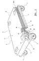
- the mobile platform assembly is in the form of a roll pallet (1) having a generally oblong rectangular platform (2) formed as a plastics injection moulding which is carried on four ground engaging castored wheels that are attached to the underside of the platform.
- the platform (2) has a flat horizontal deck (4), a pair of longitudinally extending, laterally spaced and parallel side edges (5 and 7) and a pair of laterally extending, longitudinally spaced and parallel end edges (9 and 11).
- a connecting means (13) Provided at the side edge (5) of the platform (2) and extending longitudinally thereof is a connecting means (13) and provided at the side edge (7) and extending longitudinally thereof is a further connecting means (15).
- the connecting means (13) includes an elongated connecting member (17) which extends longitudinally over the major part length of the side edge (5) and is hingedly mounted on the platform (2) by a horizontal pivot pin (19) that extends longitudinally parallel to the side edge (5).
- the connecting member (17) is mounted by the pin (19) to be capable of pivotal movement towards and from the side edge (5) between a first position in which the connecting member is accommodated unobtrusively within a longitudinally extending recess (21) in a wall 21A of the side edge 5 of the platform and a second position in which the connecting member is displaced outwardly of the recess (21) to stand proud of the side edge (5) and be presented for connecting or ganging together the wheeled pallet (1) with a second similar wheeled pallet in side-by-side relationship as will be described hereinafter.
- FIG. 1 the connecting member (17) is shown with part length (17A) thereof in its first position and part length (17B) thereof in its second position.
- the aforementioned first position for the connecting member (17A) is also shown in Figure 4 and the aforementioned second position for the connecting member (17B) is also shown in Figure 3.
- the connecting member (17) has a longitudinally extending upstanding flange (23) which in the first position (17A) (see Figure 4) of the connecting member sits unobtrusively within the recess (21) in the side edge (5).
- the platform (2) is, predominantly, a hollow injection moulding and provided on the connecting member (17) is a leg (25) which extends laterally relative to the flange (23) and inwardly of the platform (2).
- an upstanding foot (27) Provided at the free end of the leg (25) is an upstanding foot (27).
- the leg (25) of the connecting member projects into the platform (2) beneath a bottom end part (29) of the side edge (21A) .
- the first position of adjustment (17A) for the connecting member is determined when the flange (23) abuts the side edge wall (21A) within the recess (21). It can be seen from Figures 3 and 4 that the leg (25) has a stud, rib or other small projection (31) upstanding between the flange (23) and the foot (27). As the connecting member is pivoted into its first position (17A), the projection (31) abuts and slide or snaps beneath the end part (29) of the side edge wall (21A) as permitted by resilient interference between the plastics material of the leg (25) and of side wall part (29). When the connecting member (17) is in its first position (17A), it is releasably retained in that position by abutment of the side edge end part (29) between the flange (23) and the projection (31).
- the connecting member (17) is pivotally displaced laterally outwardly of the platform (2) by rotation about the pin (19) from the first position (17A) towards the second position 178, the projection (31) abuts the side edge part (29) so that the plastics material deforms sufficiently for the projection (31) to slide or snap beneath the part (29).
- the connecting member can pivot to its second position (17B) which is determined, as will be seen from Figure 3, when its foot (27) abuts or stops against the bottom part (29) of the side edge wall (21A).
- the upwardly directed flange (23) defines partly with the side edge wall (21A) within the recess (21) an upwardly open channel (33) which extends longitudinally over the major part length of the side edge (5).
- connection member (17) may be carried out by manual handling of the connecting member to simply pivot it about the pin (19). Cut-outs (35) are moulded into the platform (2) at the side edge (5) to permit convenient access for manual engagement with the connecting member when it is in its first position (17A).
- the connecting means (15) provided at the side edge (7) is located unobtrusively within the wall of that side edge and is moulded integral with the platform (2). More particularly, the connecting means (15) has a downwardly directed flange (41) which extends longitudinally over the major part length of the side edge (7).
- the flange (41) defines with an inner wall part (43) of the side edge (5) a downwardly open channel (45), the length of which corresponds to that of the flange (41) and which channel opens at (45A) ( Figure 2) into the end edge (9).
- the connecting means (13 and 15) provided on the platform (2) permits two or more similar wheeled pallets (1) to be connected or ganged together in side-by-side relationship for unified mobility.
- the connecting member (17) of the pallet (1A) is displaced laterally outwardly of its platform to its second position (17B).
- a leading edge (23A) (see Figure 1) of the flange (23) is now positioned within the end opening (45A) of the downwardly open channel (45) in the end edge (9) of the pallet (1B) by appropriate manoeuvring of the two pallets (1A and 1B).
- the pallets (1A and 1B) are now displaced longitudinally and in parallel relationship relative to each other so that the upwardly directed flange (23) of the pallet (1A) is received within, and slides longitudinally along, the downwardly open channel (45) of the pallet (1B) whilst the downwardly directed flange (41) of the pallet (1B) is received longitudinally within the upwardly open channel (33) presented at the side edge (5) of the wheeled pallet (1A) (see Figure 3).
- the flanges as aforementioned slide along the respective channels as the platforms (2) of the pallets (1A and 1B) move into side-by-side and connected or ganged together relationship which may be determined when the leading end (23A) of the flange (23) on the pallet (1A) abuts a convenient stop (not shown) at the end of the channel (45) remote from its end (45A) on the pallet (1B).
- the leading end (23A) of the connecting member is tapered or rounded to present a lead in profile for convenience of engaging with the open end (45A) of the channel (45).
- the wheeled pallet (1) has a retaining means in the form of a latch (51) (see Figure 2) to prevent relative longitudinal displacement between the wheeled pallets (1A and 1B) when they are connected together.
- the latch (51) is mounted by a pivot pin (53) on the side edge (7) longitudinally remote from the channel open end (45A) and has a nose (55).
- a rebate (57) Located in the connecting member (17) adjacent to its leading end (23A) is a rebate (57).
- the latch and connecting member are arranged so that as the flange (23) of wheeled pallet (1A) is displaced along the channel (45) of the pallet (1B) the leading end (23A) of the flange (23) rides beneath the nose (55) of the latch (51) and thereafter the nose (55) drops into the rebate (57) in the flange (23) thereby securing the wheel pallets (1A and 1B) against longitudinal displacement relative to each other.
- the nose end (55) of the latch is weighted to be biassed for rotation about the pivot pin (53) in a sense to engage with the rebate (57).
- a pedal end (59) of the latch (51) can be displaced by an operative to lift the nose (55) from the rebate (57) and thereby release the latch of pallet (1B) from the flange (23) of pallet (1A) to permit the two pallets to be slidably displaced longitudinally relative to each other for their disconnection.
- the wheeled pallets will be used as individual units and retained as such even though they may be parked with their platforms disposed in side-by-side relationship, possibly for storage or vehicular transportation.
- the connecting members (17) can be displaced inwardly of their respective platforms to the unobtrusive first position (17A) (see Figure 4).
- the independent wheeled pallets (1A and 1B) may be manoeuvred and parked in side-by-side relationship with the side edge (5) of pallet (1A) in abutment with side edge (7) of pallet (1B).
- the platform (2) is hollow and of a plastics blow moulded or rotationally moulded structure.
- the connecting means (15) in the longitudinally extending side edge (7) is again moulded integrally with the platform and is unobtrusive in that side edge comprising an upwardly directed longitudinal flange (61) which partly defines an upwardly open channel (63).
- the connecting means (13) in the longitudinally extending side edge (5) again comprises a connecting member (17) which is hingedly mounted by a pin (19) on the platform (2) for pivotal movement between the first position (17A) where the connecting member is withdrawn or located within the platform to be unobtrusive at its side edge (5) and the second position (17B) ( Figure 5) where the connecting member is presented for connection to the side edge (7) of an adjacent similar pallet.
- the connecting member (17) has a downwardly directed flange (65) and wholly defines, partly with the flange (55), a longitudinally extending downwardly open channel (67).
- the wheeled pallets (1A and 1B) are connected or ganged together by locating the flange (65) of pallet (1A) within and sliding it along the channel (63) of pallet (1B) whilst the flange (61) is simultaneously located within and slidably displaced along the downwardly open channel (67). If the modified pallet is to be used independently, the connecting member may be withdrawn to its unobtrusive position (17A) in the side edge (5) as shown in Figure 6.
- the connecting member may be releasably retained in this latter position by its frictional engagement with a rib (71) on the platform (2) over which rib the connecting member (17) may slide to progressively increase its frictional retention as the connecting member is displaced progressively into the platform (2) .
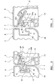
- Figures 7 and 8 show a modification for the roll pallet of Figures 1 to 4 by which the connecting member (17) is automatically displaced from its first position (17A) to its second position (17B) as the roll pallet (1A) is in the process of being connected to the roll pallet (1B).
- This automatic displacement of the connecting member (17) is effected by the provision of guide surfaces at the side edges (5 and 7). These guide surfaces interact with each other and with the connecting member during manoeuvring of the pallets (1A and 1B) longitudinally relative to each other to cause the connecting member of the pallet (1A) to "flip" over from its first position into longitudinal alignment with the open end (45A) of the downwardly open channel (45) of the pallet (1B).
- the guide surfaces at the side edge (5) are provided in a rebate (81) of that side edge adjacent to the leading end (23A) of the connecting member and the end edge (11) of the platform (2) ; these guide surfaces are a flat face (83) which extends from the side wall (21), is stepped back from the side edge face (5) and is parallel therewith, and a ramp face (85) which extends at an acute angle between the side edge face (5) and the face (83).
- the guide surfaces at the side edge (7) are provided in a rebate (91) of that side edge adjacent to the end opening (45A) of the downwardly open channel (45) and the end edge (9) of the platform (2); these guide surfaces are a flat face (93) which is stepped back from the side edge face (7) and is parallel therewith, a ramp face (95) which extends at an acute angle between the side edge (7) and the face (93) and a lead-in face (97) that is located on a nose (99) which projects longitudinally from the downwardly directed flange (41) adjacent to the end opening (45A) of the channel (45).
- the lead-in face (97) extends at an acute angle relative to the longitudinal extent of the nose (99) to provide the latter with an apical leading edge (100).
- the pallet (1B) is displaced longitudinally relative to the pallet (1A) for leading edge (100) of the nose (99) of pallet (1B) to approach and enter between the connecting member (17A) and the side wall (21) of pallet (1A).
- the leading edge (100) of the nose (99) of pallet (1B) enters as a wedge between the flange (23) of the connecting member (in its position 17A) of pallet (1B) and the bottom part (29) of the side wall (21A) of that pallet.
- the connecting member (17) can be displaced from its second position (17B) to its first position (17A). This displacement can be effected manually as previously described. If required however, the connecting member (17) can be biassed relative to the platform (2), conveniently by a plastic spring part or member (not shown) to be displaced automatically from its second position to its first position as the connecting means (13 and 15) between the two pallets (1A and 1B) move out of engagement with each other.
- a biassed connecting member (17) is provided, the modification shown in Figures 7 and 8 will still be effective as the connecting member will simply be displaced automatically from its first position (17A) to its second position (17B) against the biassing on that member.
- Figure 9 illustrates an alternative technique for connecting together the two pallets (1A) and (1B) having the modifications shown in Figures 7 and 8.
- the two pallets are shown in plan and disposed with their side edges parallel and their decks 4 in echelon.
- the guide face (93) of pallet (1B) is in face-to-face abutment with the side edge face (5) of pallet (1A) so that the apical leading edge (100) of nose (99) on pallet (1B) is located in the rebate (81) of pallet (1A) and in longitudinal alignment with the slight clearance between the flange (23) of the connecting member (17A) of pallet (1A) and the side wall part (29) of that pallet.
- lateral clearance may be provided between the nose (99) and side edge face (7) of pallet (1B) and the face (83) in rebate (81) of pallet (1A).
- the pallet (1B) is now displaced longitudinally relative to pallet (1A) so that the guide face (93) slides over the side edge face (5) as the nose (99) of pallet (1B) engages behind the flange (23) of pallet (1A) (that is between that flange and the wall part 29).
- the ramp (95) of pallet (1B) abuts the ramp (85) of pallet (1A) to provide the previously mentioned cam effect whereby pallet (1B) is subjected to lateral displacement relative to and in a direction outwardly of pallet (1A), causing the nose (99) of pallet (1B) to displace the connecting member (17) of pallet (1A) from its position (17A) towards its position (17B).
- the nose (99) of pallet (1B) displaces the connecting member of pallet (1A) to its second position (17B) in longitudinal alignment with the channel (45) of pallet (1B) as the nose (99) and side edge face (7) of pallet 1B move into face-to-face abutment with the side edge face (5) of pallet (1A).
- the two pallets can be displaced longitudinally relative to each other to complete their connection in side-by-side relationship.
Landscapes
- Engineering & Computer Science (AREA)
- Transportation (AREA)
- Mechanical Engineering (AREA)
- Chemical & Material Sciences (AREA)
- Combustion & Propulsion (AREA)
- Pallets (AREA)
- Steering Devices For Bicycles And Motorcycles (AREA)
- Handcart (AREA)
- Escalators And Moving Walkways (AREA)
- Vehicle Body Suspensions (AREA)
- Devices For Conveying Motion By Means Of Endless Flexible Members (AREA)
Applications Claiming Priority (2)
| Application Number | Priority Date | Filing Date | Title |
|---|---|---|---|
| GB0003211A GB2359061B (en) | 2000-02-11 | 2000-02-11 | A mobile platform assembly |
| GB0003211 | 2000-02-11 |
Publications (2)
| Publication Number | Publication Date |
|---|---|
| EP1125818A1 true EP1125818A1 (de) | 2001-08-22 |
| EP1125818B1 EP1125818B1 (de) | 2004-03-17 |
Family
ID=9885445
Family Applications (1)
| Application Number | Title | Priority Date | Filing Date |
|---|---|---|---|
| EP00311383A Expired - Lifetime EP1125818B1 (de) | 2000-02-11 | 2000-12-19 | Mobile Plattform |
Country Status (5)
| Country | Link |
|---|---|
| EP (1) | EP1125818B1 (de) |
| AT (1) | ATE261835T1 (de) |
| DE (1) | DE60009027T2 (de) |
| ES (1) | ES2216830T3 (de) |
| GB (1) | GB2359061B (de) |
Cited By (6)
| Publication number | Priority date | Publication date | Assignee | Title |
|---|---|---|---|---|
| GB2409850A (en) * | 2004-01-08 | 2005-07-13 | Linpac Mouldings Ltd | Transportation system including a mobile platform |
| EP2058150A1 (de) * | 2007-11-08 | 2009-05-13 | Linpac Allibert Europe | Plattform mit Rollen |
| EP2042403A3 (de) * | 2007-09-27 | 2009-09-30 | Rehrig Pacific Company | Koppelbarer Rollwagen |
| RU2412102C1 (ru) * | 2007-05-11 | 2011-02-20 | Кхс Аг | Способ и устройство для разгрузки роликовых тележек с поддонов и транспортирования |
| JP2019182243A (ja) * | 2018-04-11 | 2019-10-24 | 株式会社ピカコーポレイション | 運搬台車の連結装置 |
| DE102006017124B4 (de) | 2005-04-28 | 2022-03-03 | Industrie-Service Gmbh | Rollgestellsystem |
Families Citing this family (7)
| Publication number | Priority date | Publication date | Assignee | Title |
|---|---|---|---|---|
| GB2377689A (en) * | 2001-05-17 | 2003-01-22 | Paxton C G Ltd | Interlocking Dolly. |
| CA3004402C (en) * | 2015-11-06 | 2020-05-26 | Orbis Corporation | Connectable dolly |
| US10086973B2 (en) | 2015-12-30 | 2018-10-02 | Orbis Corporation | Pallet and dolly with bail arm |
| US10279830B2 (en) | 2016-11-08 | 2019-05-07 | Orbis Corporation | Dished caster wheel pocket for a platform or dolly |
| US11173939B2 (en) | 2018-08-20 | 2021-11-16 | Rehrig Pacific Company | Bakery dolly |
| GB2587322B (en) * | 2019-08-16 | 2023-09-27 | Alison Handling Services Ltd | Transport dolly with interlocking means |
| US12558930B2 (en) | 2021-02-08 | 2026-02-24 | Orbis Corporation | Detachable dolly training connector |
Citations (4)
| Publication number | Priority date | Publication date | Assignee | Title |
|---|---|---|---|---|
| GB2263684A (en) * | 1992-02-03 | 1993-08-04 | Lin Pac Mouldings | Interlockable pallets. |
| GB2280166A (en) * | 1993-07-12 | 1995-01-25 | Lin Pac Mouldings | Mobile platform assembly. |
| DE19703545A1 (de) * | 1996-02-02 | 1997-08-07 | Rubbermaid Commercial Products | Abfallbehälterträger |
| EP0807542A1 (de) * | 1996-05-15 | 1997-11-19 | Valeo Equipements Electriques Moteur | Lastförderwagen mit Befestigungsmitteln |
Family Cites Families (1)
| Publication number | Priority date | Publication date | Assignee | Title |
|---|---|---|---|---|
| GB9609928D0 (en) * | 1996-05-13 | 1996-07-17 | Lin Pac Mouldings | A roller platform |
-
2000
- 2000-02-11 GB GB0003211A patent/GB2359061B/en not_active Expired - Fee Related
- 2000-12-19 EP EP00311383A patent/EP1125818B1/de not_active Expired - Lifetime
- 2000-12-19 AT AT00311383T patent/ATE261835T1/de not_active IP Right Cessation
- 2000-12-19 DE DE60009027T patent/DE60009027T2/de not_active Expired - Lifetime
- 2000-12-19 ES ES00311383T patent/ES2216830T3/es not_active Expired - Lifetime
Patent Citations (4)
| Publication number | Priority date | Publication date | Assignee | Title |
|---|---|---|---|---|
| GB2263684A (en) * | 1992-02-03 | 1993-08-04 | Lin Pac Mouldings | Interlockable pallets. |
| GB2280166A (en) * | 1993-07-12 | 1995-01-25 | Lin Pac Mouldings | Mobile platform assembly. |
| DE19703545A1 (de) * | 1996-02-02 | 1997-08-07 | Rubbermaid Commercial Products | Abfallbehälterträger |
| EP0807542A1 (de) * | 1996-05-15 | 1997-11-19 | Valeo Equipements Electriques Moteur | Lastförderwagen mit Befestigungsmitteln |
Cited By (9)
| Publication number | Priority date | Publication date | Assignee | Title |
|---|---|---|---|---|
| GB2409850A (en) * | 2004-01-08 | 2005-07-13 | Linpac Mouldings Ltd | Transportation system including a mobile platform |
| GB2409850B (en) * | 2004-01-08 | 2006-08-30 | Linpac Mouldings Ltd | Transportation system |
| DE102006017124B4 (de) | 2005-04-28 | 2022-03-03 | Industrie-Service Gmbh | Rollgestellsystem |
| RU2412102C1 (ru) * | 2007-05-11 | 2011-02-20 | Кхс Аг | Способ и устройство для разгрузки роликовых тележек с поддонов и транспортирования |
| EP2042403A3 (de) * | 2007-09-27 | 2009-09-30 | Rehrig Pacific Company | Koppelbarer Rollwagen |
| US8317204B2 (en) | 2007-09-27 | 2012-11-27 | Rehrig Pacific Company | Linkable dolly |
| EP2058150A1 (de) * | 2007-11-08 | 2009-05-13 | Linpac Allibert Europe | Plattform mit Rollen |
| FR2923443A1 (fr) * | 2007-11-08 | 2009-05-15 | Linpac Allibert Europ Soc Par | Plateforme a roulettes. |
| JP2019182243A (ja) * | 2018-04-11 | 2019-10-24 | 株式会社ピカコーポレイション | 運搬台車の連結装置 |
Also Published As
| Publication number | Publication date |
|---|---|
| GB0003211D0 (en) | 2000-04-05 |
| ATE261835T1 (de) | 2004-04-15 |
| ES2216830T3 (es) | 2004-11-01 |
| GB2359061B (en) | 2003-11-26 |
| EP1125818B1 (de) | 2004-03-17 |
| DE60009027D1 (de) | 2004-04-22 |
| DE60009027T2 (de) | 2004-10-28 |
| GB2359061A (en) | 2001-08-15 |
Similar Documents
| Publication | Publication Date | Title |
|---|---|---|
| EP1125818B1 (de) | Mobile Plattform | |
| US11554898B2 (en) | Coupleable crate | |
| US7003836B2 (en) | Portable car ramp | |
| AU2016309923C1 (en) | Stackable suitcase, arrangement comprising two suitcases stacked one above the other and method for stacking two suitcases | |
| US11279518B2 (en) | Stackable system container and transport system | |
| US8657307B2 (en) | Modular rolling container assembly | |
| US7641066B2 (en) | Collapsible container | |
| GB2280166A (en) | Mobile platform assembly. | |
| US4564984A (en) | Positioning cone for containers | |
| US5544998A (en) | Selectively retractable vehicle load floor | |
| CN212165168U (zh) | 一种用于将部件附接到行李制品的卡扣配合互锁 | |
| US4988131A (en) | Interlocking sections for portable floors and the like | |
| US5794540A (en) | Child's easel/table | |
| US7717283B2 (en) | Collapsible container | |
| GB2447566A (en) | Collapsible container with support arms which allow stacking | |
| EP0254724B1 (de) | Hebehaken | |
| AU617969B2 (en) | Interlocking sections for portable floors and the like | |
| GB2263684A (en) | Interlockable pallets. | |
| GB2244972A (en) | Container with pivotally mounted handle | |
| EP0807563B1 (de) | Rollpalette | |
| GB2377689A (en) | Interlocking Dolly. | |
| GB2313103A (en) | Coupling mobile platforms | |
| GB2293160A (en) | Collapsible container or pallet frame | |
| CA3083887C (en) | Coupleable crate | |
| US20250136323A1 (en) | Dual connector |
Legal Events
| Date | Code | Title | Description |
|---|---|---|---|
| PUAI | Public reference made under article 153(3) epc to a published international application that has entered the european phase |
Free format text: ORIGINAL CODE: 0009012 |
|
| AK | Designated contracting states |
Kind code of ref document: A1 Designated state(s): AT BE CH CY DE DK ES FI FR GB GR IE IT LI LU MC NL PT SE TR |
|
| AX | Request for extension of the european patent |
Free format text: AL;LT;LV;MK;RO;SI |
|
| 17P | Request for examination filed |
Effective date: 20011004 |
|
| AKX | Designation fees paid |
Free format text: AT BE CH CY DE DK ES FI FR GB GR IE IT LI LU MC NL PT SE TR |
|
| GRAP | Despatch of communication of intention to grant a patent |
Free format text: ORIGINAL CODE: EPIDOSNIGR1 |
|
| GRAS | Grant fee paid |
Free format text: ORIGINAL CODE: EPIDOSNIGR3 |
|
| GRAA | (expected) grant |
Free format text: ORIGINAL CODE: 0009210 |
|
| AK | Designated contracting states |
Kind code of ref document: B1 Designated state(s): AT BE CH CY DE DK ES FI FR GB GR IE IT LI LU MC NL PT SE TR |
|
| PG25 | Lapsed in a contracting state [announced via postgrant information from national office to epo] |
Ref country code: CH Free format text: LAPSE BECAUSE OF FAILURE TO SUBMIT A TRANSLATION OF THE DESCRIPTION OR TO PAY THE FEE WITHIN THE PRESCRIBED TIME-LIMIT Effective date: 20040317 Ref country code: LI Free format text: LAPSE BECAUSE OF FAILURE TO SUBMIT A TRANSLATION OF THE DESCRIPTION OR TO PAY THE FEE WITHIN THE PRESCRIBED TIME-LIMIT Effective date: 20040317 Ref country code: FI Free format text: LAPSE BECAUSE OF FAILURE TO SUBMIT A TRANSLATION OF THE DESCRIPTION OR TO PAY THE FEE WITHIN THE PRESCRIBED TIME-LIMIT Effective date: 20040317 Ref country code: TR Free format text: LAPSE BECAUSE OF FAILURE TO SUBMIT A TRANSLATION OF THE DESCRIPTION OR TO PAY THE FEE WITHIN THE PRESCRIBED TIME-LIMIT Effective date: 20040317 Ref country code: CY Free format text: LAPSE BECAUSE OF FAILURE TO SUBMIT A TRANSLATION OF THE DESCRIPTION OR TO PAY THE FEE WITHIN THE PRESCRIBED TIME-LIMIT Effective date: 20040317 |
|
| REG | Reference to a national code |
Ref country code: GB Ref legal event code: FG4D |
|
| REG | Reference to a national code |
Ref country code: CH Ref legal event code: EP |
|
| REG | Reference to a national code |
Ref country code: IE Ref legal event code: FG4D |
|
| REF | Corresponds to: |
Ref document number: 60009027 Country of ref document: DE Date of ref document: 20040422 Kind code of ref document: P |
|
| PG25 | Lapsed in a contracting state [announced via postgrant information from national office to epo] |
Ref country code: DK Free format text: LAPSE BECAUSE OF FAILURE TO SUBMIT A TRANSLATION OF THE DESCRIPTION OR TO PAY THE FEE WITHIN THE PRESCRIBED TIME-LIMIT Effective date: 20040617 Ref country code: GR Free format text: LAPSE BECAUSE OF FAILURE TO SUBMIT A TRANSLATION OF THE DESCRIPTION OR TO PAY THE FEE WITHIN THE PRESCRIBED TIME-LIMIT Effective date: 20040617 Ref country code: SE Free format text: LAPSE BECAUSE OF FAILURE TO SUBMIT A TRANSLATION OF THE DESCRIPTION OR TO PAY THE FEE WITHIN THE PRESCRIBED TIME-LIMIT Effective date: 20040617 |
|
| REG | Reference to a national code |
Ref country code: CH Ref legal event code: PL |
|
| REG | Reference to a national code |
Ref country code: FR Ref legal event code: RN |
|
| REG | Reference to a national code |
Ref country code: ES Ref legal event code: FG2A Ref document number: 2216830 Country of ref document: ES Kind code of ref document: T3 |
|
| REG | Reference to a national code |
Ref country code: FR Ref legal event code: FC |
|
| PG25 | Lapsed in a contracting state [announced via postgrant information from national office to epo] |
Ref country code: LU Free format text: LAPSE BECAUSE OF NON-PAYMENT OF DUE FEES Effective date: 20041219 |
|
| PG25 | Lapsed in a contracting state [announced via postgrant information from national office to epo] |
Ref country code: IE Free format text: LAPSE BECAUSE OF NON-PAYMENT OF DUE FEES Effective date: 20041220 |
|
| PG25 | Lapsed in a contracting state [announced via postgrant information from national office to epo] |
Ref country code: MC Free format text: LAPSE BECAUSE OF NON-PAYMENT OF DUE FEES Effective date: 20041231 |
|
| PLBE | No opposition filed within time limit |
Free format text: ORIGINAL CODE: 0009261 |
|
| STAA | Information on the status of an ep patent application or granted ep patent |
Free format text: STATUS: NO OPPOSITION FILED WITHIN TIME LIMIT |
|
| EN | Fr: translation not filed | ||
| 26N | No opposition filed |
Effective date: 20041220 |
|
| ET | Fr: translation filed | ||
| REG | Reference to a national code |
Ref country code: IE Ref legal event code: MM4A |
|
| NLS | Nl: assignments of ep-patents |
Owner name: LINPAC MATERIALS HANDLING LIMITED Effective date: 20050909 |
|
| REG | Reference to a national code |
Ref country code: FR Ref legal event code: TP |
|
| PG25 | Lapsed in a contracting state [announced via postgrant information from national office to epo] |
Ref country code: PT Free format text: LAPSE BECAUSE OF NON-PAYMENT OF DUE FEES Effective date: 20040817 |
|
| REG | Reference to a national code |
Ref country code: GB Ref legal event code: 732E |
|
| PGFP | Annual fee paid to national office [announced via postgrant information from national office to epo] |
Ref country code: NL Payment date: 20081203 Year of fee payment: 9 |
|
| PGFP | Annual fee paid to national office [announced via postgrant information from national office to epo] |
Ref country code: AT Payment date: 20081211 Year of fee payment: 9 |
|
| PGFP | Annual fee paid to national office [announced via postgrant information from national office to epo] |
Ref country code: BE Payment date: 20090112 Year of fee payment: 9 |
|
| REG | Reference to a national code |
Ref country code: FR Ref legal event code: CD |
|
| REG | Reference to a national code |
Ref country code: GB Ref legal event code: 732E Free format text: REGISTERED BETWEEN 20100121 AND 20100127 |
|
| BERE | Be: lapsed |
Owner name: LINPAC ALLIBERT LTD Effective date: 20091231 |
|
| REG | Reference to a national code |
Ref country code: NL Ref legal event code: V1 Effective date: 20100701 |
|
| PG25 | Lapsed in a contracting state [announced via postgrant information from national office to epo] |
Ref country code: AT Free format text: LAPSE BECAUSE OF NON-PAYMENT OF DUE FEES Effective date: 20091219 |
|
| PG25 | Lapsed in a contracting state [announced via postgrant information from national office to epo] |
Ref country code: NL Free format text: LAPSE BECAUSE OF NON-PAYMENT OF DUE FEES Effective date: 20100701 Ref country code: BE Free format text: LAPSE BECAUSE OF NON-PAYMENT OF DUE FEES Effective date: 20091231 |
|
| PGFP | Annual fee paid to national office [announced via postgrant information from national office to epo] |
Ref country code: DE Payment date: 20121213 Year of fee payment: 13 |
|
| PGFP | Annual fee paid to national office [announced via postgrant information from national office to epo] |
Ref country code: IT Payment date: 20121220 Year of fee payment: 13 Ref country code: ES Payment date: 20121227 Year of fee payment: 13 |
|
| REG | Reference to a national code |
Ref country code: DE Ref legal event code: R119 Ref document number: 60009027 Country of ref document: DE |
|
| REG | Reference to a national code |
Ref country code: DE Ref legal event code: R119 Ref document number: 60009027 Country of ref document: DE Effective date: 20140701 |
|
| PG25 | Lapsed in a contracting state [announced via postgrant information from national office to epo] |
Ref country code: DE Free format text: LAPSE BECAUSE OF NON-PAYMENT OF DUE FEES Effective date: 20140701 |
|
| REG | Reference to a national code |
Ref country code: ES Ref legal event code: FD2A Effective date: 20150407 |
|
| PG25 | Lapsed in a contracting state [announced via postgrant information from national office to epo] |
Ref country code: ES Free format text: LAPSE BECAUSE OF NON-PAYMENT OF DUE FEES Effective date: 20131220 |
|
| PG25 | Lapsed in a contracting state [announced via postgrant information from national office to epo] |
Ref country code: IT Free format text: LAPSE BECAUSE OF NON-PAYMENT OF DUE FEES Effective date: 20131231 |
|
| REG | Reference to a national code |
Ref country code: FR Ref legal event code: PLFP Year of fee payment: 16 |
|
| PG25 | Lapsed in a contracting state [announced via postgrant information from national office to epo] |
Ref country code: IT Free format text: LAPSE BECAUSE OF NON-PAYMENT OF DUE FEES Effective date: 20131219 |
|
| REG | Reference to a national code |
Ref country code: FR Ref legal event code: PLFP Year of fee payment: 17 |
|
| REG | Reference to a national code |
Ref country code: GB Ref legal event code: 732E Free format text: REGISTERED BETWEEN 20170511 AND 20170517 |
|
| REG | Reference to a national code |
Ref country code: FR Ref legal event code: PLFP Year of fee payment: 18 |
|
| PGFP | Annual fee paid to national office [announced via postgrant information from national office to epo] |
Ref country code: FR Payment date: 20191219 Year of fee payment: 20 |
|
| PGFP | Annual fee paid to national office [announced via postgrant information from national office to epo] |
Ref country code: GB Payment date: 20191220 Year of fee payment: 20 |
|
| REG | Reference to a national code |
Ref country code: GB Ref legal event code: PE20 Expiry date: 20201218 |
|
| PG25 | Lapsed in a contracting state [announced via postgrant information from national office to epo] |
Ref country code: GB Free format text: LAPSE BECAUSE OF EXPIRATION OF PROTECTION Effective date: 20201218 |