EP1125874A2 - Tambour à pinces d'un magasin pour pile - Google Patents
Tambour à pinces d'un magasin pour pile Download PDFInfo
- Publication number
- EP1125874A2 EP1125874A2 EP01101176A EP01101176A EP1125874A2 EP 1125874 A2 EP1125874 A2 EP 1125874A2 EP 01101176 A EP01101176 A EP 01101176A EP 01101176 A EP01101176 A EP 01101176A EP 1125874 A2 EP1125874 A2 EP 1125874A2
- Authority
- EP
- European Patent Office
- Prior art keywords
- gripper
- drum
- cam follower
- cam
- link
- Prior art date
- Legal status (The legal status is an assumption and is not a legal conclusion. Google has not performed a legal analysis and makes no representation as to the accuracy of the status listed.)
- Granted
Links
- 238000000034 method Methods 0.000 claims abstract description 4
- 230000006835 compression Effects 0.000 description 1
- 238000007906 compression Methods 0.000 description 1
- 210000003746 feather Anatomy 0.000 description 1
- 210000003127 knee Anatomy 0.000 description 1
- 230000007257 malfunction Effects 0.000 description 1
- 230000003313 weakening effect Effects 0.000 description 1
Images


Classifications
-
- B—PERFORMING OPERATIONS; TRANSPORTING
- B65—CONVEYING; PACKING; STORING; HANDLING THIN OR FILAMENTARY MATERIAL
- B65H—HANDLING THIN OR FILAMENTARY MATERIAL, e.g. SHEETS, WEBS, CABLES
- B65H5/00—Feeding articles separated from piles; Feeding articles to machines
- B65H5/08—Feeding articles separated from piles; Feeding articles to machines by grippers, e.g. suction grippers
- B65H5/12—Revolving grippers, e.g. mounted on arms, frames or cylinders
-
- B—PERFORMING OPERATIONS; TRANSPORTING
- B65—CONVEYING; PACKING; STORING; HANDLING THIN OR FILAMENTARY MATERIAL
- B65H—HANDLING THIN OR FILAMENTARY MATERIAL, e.g. SHEETS, WEBS, CABLES
- B65H2403/00—Power transmission; Driving means
- B65H2403/50—Driving mechanisms
- B65H2403/51—Cam mechanisms
- B65H2403/512—Cam mechanisms involving radial plate cam
Definitions
- the present invention relates to printing presses, in particular a device and a method for transporting printed products according to the preamble of Claim 1.
- US 5,447,302 describes an apparatus for removing paper products from a stack in a magazine.
- the device includes a rotatably mounted one Gripper drum moving at a constant angular velocity around a central axis turns.
- a fixed cam is rigidly attached near the gripper drum.
- On Cam follower follows the outside of the cam and is at one end at one Fastened link that also rotates with the gripper drum. That I rotating link is pivotable about a pin, making a change in the cam radius can cause the link to pivot so that a other end of the link compresses or stretches a spring.
- This other end of the Link is connected to another link, which is a toggle arm can move in, on which a gripper and a gripper pad are held.
- the gripper is opened. If the Gripper and the gripper pad are braked in relation to the gripper drum the gripper closed.
- the device according to US 5,447,302 has the disadvantage that the structure of the Link is complicated, especially because a spring is necessary to the To cause cam to follow the cam follower. That repeated Compression and extension of the spring can result in frequent rotation Weakening of the spring and incorrect operation of the entire device to lead. At high speeds, high spring forces must be maintained so that the Cam follower remains on the cam and the gripper works reliably. Does it come off Follower of the cam, this can lead to malfunction or damage to the Lead gripper.
- the gripping force remains relatively constant, regardless of whether the Knee lever arm moves. Therefore a large gripping force is required for thick products, which can damage the thin products if they are on the same machine to be edited.
- the invention has for its object to provide a rotatable gripper drum is durable and has improved features at high operating speeds.
- the present invention provides a gripper drum with a drum body which is around a central axis is rotatable.
- a switching shaft can be rotated inside the drum body stored.
- a cam follower is arranged in a housing and is connected to the selector shaft Moving the control shaft is connected.
- a gripper pad with the shift shaft is connected, and a cam arranged in a housing are provided.
- the cam according to the invention arranged in a housing controls and limits the Movement of the cam follower and makes use of a spring to adjust the Cam follower unnecessary.
- a gripper pad can preferably be connected to the Cam followers are moved about a first axis, the first axis being from a Axis of the control shaft differs.
- the control shaft is preferably based on a second link connected to the gripper.
- the second link is preferably connected directly to the cam follower and drives a rack of a rack and pinion mechanism, the pinion with the Gripper is connected.
- the gripper pad is preferably directly on the first Fastened link, which by a support member, which is between the first Link and the cam follower is attached is driven.
- the gripper is preferably spring-loaded, so that a spring is directly between the spring and a spring support attached to the rotatable drum. Since the Spring in the present invention only counteracts the gripper, it can be compact and do not deform when accelerated, as is known Devices was often the case. In addition, the gripping force can preferably be increased if the gripped product becomes thicker because the spring is only on the gripper acts. This enables a small initial load for thin products to open, which leads to less damage to these products. Another one The consequence is less wear on the components and the fact that for the entire system less torque is needed.
- the present invention thus provides a gripper drum that one by one Center axis rotatable drum body, one on the periphery of the gripper drum movable gripper, a gripper pad to interact with the gripper and one Cam follower using a first link with the gripper pad is connected and by means of a second connecting element which is different from the first Connection link differs, with which the gripper is connected.
- the present invention also provides a method for grasping Printed matter proposed, which comprises the following steps: turning one Drum around a central axis, moving a cam follower in one in a housing arranged cam and gripping a printed product with a gripper, which on the Cam follower is attached.
- cam housing denotes a cam with a Groove or a slot in which a cam follower moves and which the cam both in a radially outward and a radially inward movement limited.
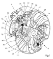
- the gripper drum 10 which has a drum body 12 which rotates about a central axis 14 in the direction of the arrow 16.
- the gripper drum 10 is preferably driven at a constant speed by a drive device having a drive axis which rotates about the central axis 14 and fits in the middle of the drum body 14 .
- the gripper drum 10 preferably also includes a pin 20 attached to one end of the support member 22. At the other end of the support member 22, a gripper pad connecting member 24 is fastened by means of a pin 23 and is rotatable about the axis 26.
- a gripper pad 28 is attached to one end of the gripper pad connector 24.
- the gripper pad 28 is preferably made of a material that is exposed to high friction can be e.g. Rubber.
- a cam follower 120 (FIG. 3) is on the side of the drum that is not shown connected to a shaft that supports on the side shown in Fig. 1
- Cam follower link 30, which is connected to the support member 22 by means of a pin 20 is attached.
- the cam follower link 30 is firmly clamped to a shaft 32.
- the shaft 32 also rotates a rack 34 with a pinion 36 one Rack mechanism interacts.
- the pinion 36 is with a shaft 38 connected, on which a gripper 40 with the gripper end 42 is located.
- the gripper end 42 is by a spring 46 which is arranged on a spring bearing 44 is connected to the drum body 12, spring-loaded and is in a closed position.
- the gripper 40 and the gripper support 28 can be moved relative to the drum body 12 within a slot 49 on the periphery of the drum body 12.
- a second gripper device 6, similar to that described above, is rotated 180 degrees arranged on the drum body 12.
- the device is preferably symmetrical to the gripper 7 on the other side of the Support drum 10. However, on the opposite side of the drum there will be a Gripper pad moves by means of the axis 26, which is why no need for one Support member similar to the support member 22 on this side of the drum more.
- a bracket 130 is on the opposite side of the Gripper drum, which is not shown in FIG. 1, at the other end of the shaft 32 attached.
- a cam follower 120 is attached to the post 130 and extends in an in a cam 50 disposed in a housing as shown in FIG. 4.
- the gripper drum 10 operates as follows: When the gripper drum body 14 rotates, the cam follower 120 follows a control cam 52 arranged in a housing Cam 50 as shown in FIG. 4.
- the cam 50 arranged in a housing is located on the side of the drum body 12 to receive the cam follower 120.
- the gripper 40 In a portion of the cam 52 that has an inner radius 54 is the gripper 40 open and the gripper 40 and the gripper pad 28 are in the groove 49 on the Outer periphery of the drum body 12 moves forward.
- cam follower 20 When the cam follower 20 reaches a portion of the cam 52 that is a larger one Has radius 56, cam follower 120 moves radially outward, which axis 32 rotates counterclockwise as shown in FIG. 1.
- the link 22 then pulls at one end of the gripper pad 24 to rotate the axis 26 clockwise, as in FIG Fig. 1 is shown with an arrow.
- the gripper pad 28 thus moves backwards with respect to the rotating drum body 12 (and opposite the arrow 16 in Fig. 1).
- the axis 26 On the opposite side of the drum 10, the axis 26 is activated Gripper support member to also move the gripper support of the gripper 7 backwards.
- the rack 34 on the shaft 32 is caused to oppose the To rotate clockwise because the cam follower 120 rotates the shaft 32 counterclockwise moved as shown in Fig. 1.
- the pinion 36 rotates clockwise, as does that Shaft 38, which makes the gripper 40 rotate.
- the gripper end 42 thus moves backwards (against the direction of arrow 16) in the groove 49 and finally closes the Gripper pad 28, wherein it grips a printed product on a magazine.
- the opposite side of drum 10 may include a similar rack, which is mounted on the shaft 32 and activates a similar pinion mechanism.
- the spring 44 and the positioning of the gripper end 42 with respect to the gripper pad 28 can control the gripping strength of the gripping in the closed position.
- the spring 44 is intended to create the gripping force for thicker products.
- Fig. 2 shows the movement of a gripper end 42 and the gripper pad 28 (Fig. 1) at Grasping a product 60.
- the gripper pad 28 is in position 28A and is separate from that Gripper end 42 in position 42A.
- cam follower 120 is in position 20B moves, the gripper pad 28 moves forward to position 28B and that Gripper end in position 42B.
- the cam follower is in position 20C moves, the gripper pad 28 moves back into the slot 49 (Fig. 1) opposite to direction 16.
- the movement of drum 10 in direction 16 is slightly faster than this backward movement, so that the gripper pad 28 is always still moving in direction 16, but slower than drum 10. Has at the same time the gripper end 42 moves to position 42 C.
- cam follower 120 moves outward to position 20D, they engage Gripper pad 28 in position 28D and the gripper end 42 in position 42D Product 60 from a stacking magazine. While the cam follower is in position 20E moved, the gripped product is moved forward, so that the The gripper end 42 and the gripper support 28 are in positions 42E and 28E, respectively.
- the axis of rotation of the gripper pad link 24 and the The axis of rotation of the drum 10 is not the same, which enables better gripping characteristics would.
Landscapes
- Engineering & Computer Science (AREA)
- Mechanical Engineering (AREA)
- Sheets, Magazines, And Separation Thereof (AREA)
- Specific Conveyance Elements (AREA)
- Feeding Of Articles By Means Other Than Belts Or Rollers (AREA)
- Supply, Installation And Extraction Of Printed Sheets Or Plates (AREA)
- Discharge By Other Means (AREA)
- Facsimile Scanning Arrangements (AREA)
Applications Claiming Priority (2)
| Application Number | Priority Date | Filing Date | Title |
|---|---|---|---|
| US09/506,625 US6308625B1 (en) | 2000-02-18 | 2000-02-18 | Hopper gripper drum |
| US506625 | 2000-02-18 |
Publications (3)
| Publication Number | Publication Date |
|---|---|
| EP1125874A2 true EP1125874A2 (fr) | 2001-08-22 |
| EP1125874A3 EP1125874A3 (fr) | 2002-12-18 |
| EP1125874B1 EP1125874B1 (fr) | 2005-12-07 |
Family
ID=24015351
Family Applications (1)
| Application Number | Title | Priority Date | Filing Date |
|---|---|---|---|
| EP01101176A Expired - Lifetime EP1125874B1 (fr) | 2000-02-18 | 2001-01-24 | Tambour à pinces d'un magasin pour pile |
Country Status (5)
| Country | Link |
|---|---|
| US (2) | US6308625B1 (fr) |
| EP (1) | EP1125874B1 (fr) |
| JP (1) | JP4741091B2 (fr) |
| AT (1) | ATE312038T1 (fr) |
| DE (2) | DE50108269D1 (fr) |
Families Citing this family (3)
| Publication number | Priority date | Publication date | Assignee | Title |
|---|---|---|---|---|
| US7628109B2 (en) * | 2005-07-26 | 2009-12-08 | Hewlett-Packard Development Company, L.P. | Image transfer mechanism |
| DE102004014868A1 (de) | 2004-03-26 | 2005-10-13 | Heidelberger Druckmaschinen Ag | Drehzahlabhängige Andrückkraft |
| JP5422458B2 (ja) * | 2010-03-25 | 2014-02-19 | 富士フイルム株式会社 | 媒体搬送装置及び画像形成装置並びに媒体搬送方法 |
Family Cites Families (8)
| Publication number | Priority date | Publication date | Assignee | Title |
|---|---|---|---|---|
| CS165124B1 (fr) * | 1973-04-18 | 1975-11-28 | ||
| JPS5346817A (en) * | 1976-10-09 | 1978-04-26 | Sato Yoshihisa | Device for holding and taking book for use in automatic binding machine |
| CH641112A5 (de) | 1979-10-17 | 1984-02-15 | Grapha Holding Ag | Anleger fuer druckbogen. |
| DE3508697A1 (de) * | 1985-03-12 | 1986-09-25 | M.A.N.- Roland Druckmaschinen AG, 6050 Offenbach | Vorrichtung zur steuerung von greifern in bogenrotationsdruckmaschinen |
| US4815870A (en) * | 1987-10-22 | 1989-03-28 | Eastman Kodak Company | Receiver clamping arrangement for thermal printers |
| DE4343146C2 (de) | 1993-03-12 | 2000-02-17 | Heidelberger Druckmasch Ag | Vorrichtung zum Vereinzeln von Papierprodukten, zum Beispiel Signaturen und Zeitungen von einem Stapel mittels einer rotierbar gelagerten Greifertrommel |
| DE19826331A1 (de) | 1998-06-12 | 1999-12-16 | Wacker Chemie Gmbh | Verfahren zur Befestigung von Behälter-Einstellsäcken |
| DE59801959D1 (de) * | 1998-06-22 | 2001-12-06 | Grapha Holding Ag | Verfahren für das rittlingsweise Beschicken einer Sammelstrecke mit gefalzten Druckbogen |
-
2000
- 2000-02-18 US US09/506,625 patent/US6308625B1/en not_active Expired - Lifetime
-
2001
- 2001-01-24 DE DE50108269T patent/DE50108269D1/de not_active Expired - Lifetime
- 2001-01-24 EP EP01101176A patent/EP1125874B1/fr not_active Expired - Lifetime
- 2001-01-24 DE DE10103042A patent/DE10103042A1/de not_active Withdrawn
- 2001-01-24 AT AT01101176T patent/ATE312038T1/de not_active IP Right Cessation
- 2001-02-15 JP JP2001038247A patent/JP4741091B2/ja not_active Expired - Fee Related
- 2001-09-13 US US09/952,094 patent/US6701840B2/en not_active Expired - Fee Related
Also Published As
| Publication number | Publication date |
|---|---|
| DE10103042A1 (de) | 2001-08-23 |
| DE50108269D1 (de) | 2006-01-12 |
| JP4741091B2 (ja) | 2011-08-03 |
| EP1125874A3 (fr) | 2002-12-18 |
| EP1125874B1 (fr) | 2005-12-07 |
| US6701840B2 (en) | 2004-03-09 |
| US20020043169A1 (en) | 2002-04-18 |
| JP2001278467A (ja) | 2001-10-10 |
| US6308625B1 (en) | 2001-10-30 |
| ATE312038T1 (de) | 2005-12-15 |
Similar Documents
| Publication | Publication Date | Title |
|---|---|---|
| DE10001580B4 (de) | Greifervorrichtung | |
| DE3434009A1 (de) | Werkstueck-handhabungsgeraet | |
| DE4343146C2 (de) | Vorrichtung zum Vereinzeln von Papierprodukten, zum Beispiel Signaturen und Zeitungen von einem Stapel mittels einer rotierbar gelagerten Greifertrommel | |
| DE2163499A1 (de) | Werkzeugmaschine mit automatischer werkzeug-wechselvorrichtung | |
| DE19857507A1 (de) | Falzapparat für Rotationsdruckmaschinen | |
| EP0484653A1 (fr) | Système de décélération dans une plieuse pour machine à imprimer rotative | |
| DE4004352C1 (fr) | ||
| EP0958919B1 (fr) | Dispositif de préhension par dépression dans un dispositif de retournement d'une machine d'impression rotative à feuilles | |
| DE2227667C2 (de) | "Mehrfarben-Bogen-Rotationsdruckmaschine" | |
| DE19650312A1 (de) | Umblättervorrichtung | |
| DE10103042A1 (de) | Stapelmagazingreifertrommel | |
| DE10061703A1 (de) | Greifersystem mit verstellbarer Geschwindigkeit | |
| DE69002873T2 (de) | Selbstzentrierendes Futter mit balancierenden Spannbacken. | |
| CH627422A5 (de) | Einrichtung fuer die behandlung von schriftstuecken, die zwischen behandlungsstationen befoerdert werden. | |
| CH696538A5 (de) | Signaturenübergabevorrichtung. | |
| DE60222987T2 (de) | Falzklappenzylinder | |
| EP0985618A2 (fr) | Pince pour saisir des produits plats | |
| DE19729122B4 (de) | Übergabetrommel mit einem Mechanismus für die Handhabung von Signaturen | |
| DE2834045C3 (de) | Bogenübergabevorrichtung zur paßgenauen Übergabe eines Druckbogens | |
| DE19953669B4 (de) | Hebevorrichtung | |
| DE69313242T2 (de) | Vorrichtung zum Spannen von Druckplatten an Offsetdruckmaschinen | |
| DE1436520C (de) | Einrichtung zum Übertragen von Signaturen auf einen Stiftzylinder | |
| EP0392277B1 (fr) | Dispositif de préhension pour une bobine de mèche d'un banc à broches | |
| DE102016001046A1 (de) | Greifvorrichtung | |
| WO2011058073A1 (fr) | Dispositif de serrage pour un arbre et procédé pour serrer ce dernier |
Legal Events
| Date | Code | Title | Description |
|---|---|---|---|
| PUAI | Public reference made under article 153(3) epc to a published international application that has entered the european phase |
Free format text: ORIGINAL CODE: 0009012 |
|
| AK | Designated contracting states |
Kind code of ref document: A2 Designated state(s): AT BE CH CY DE DK ES FI FR GB GR IE IT LI LU MC NL PT SE TR |
|
| AX | Request for extension of the european patent |
Free format text: AL;LT;LV;MK;RO;SI |
|
| PUAL | Search report despatched |
Free format text: ORIGINAL CODE: 0009013 |
|
| AK | Designated contracting states |
Kind code of ref document: A3 Designated state(s): AT BE CH CY DE DK ES FI FR GB GR IE IT LI LU MC NL PT SE TR |
|
| AX | Request for extension of the european patent |
Free format text: AL;LT;LV;MK;RO;SI |
|
| 17P | Request for examination filed |
Effective date: 20021118 |
|
| AKX | Designation fees paid |
Designated state(s): AT BE CH CY DE DK ES FI FR GB GR IE IT LI LU MC NL PT SE TR |
|
| 17Q | First examination report despatched |
Effective date: 20030826 |
|
| RAP1 | Party data changed (applicant data changed or rights of an application transferred) |
Owner name: GOSS INTERNATIONAL AMERICAS, INC. |
|
| GRAP | Despatch of communication of intention to grant a patent |
Free format text: ORIGINAL CODE: EPIDOSNIGR1 |
|
| GRAS | Grant fee paid |
Free format text: ORIGINAL CODE: EPIDOSNIGR3 |
|
| GRAA | (expected) grant |
Free format text: ORIGINAL CODE: 0009210 |
|
| AK | Designated contracting states |
Kind code of ref document: B1 Designated state(s): AT BE CH CY DE DK ES FI FR GB GR IE IT LI LU MC NL PT SE TR |
|
| PG25 | Lapsed in a contracting state [announced via postgrant information from national office to epo] |
Ref country code: IT Free format text: LAPSE BECAUSE OF FAILURE TO SUBMIT A TRANSLATION OF THE DESCRIPTION OR TO PAY THE FEE WITHIN THE PRESCRIBED TIME-LIMIT;WARNING: LAPSES OF ITALIAN PATENTS WITH EFFECTIVE DATE BEFORE 2007 MAY HAVE OCCURRED AT ANY TIME BEFORE 2007. THE CORRECT EFFECTIVE DATE MAY BE DIFFERENT FROM THE ONE RECORDED. Effective date: 20051207 Ref country code: IE Free format text: LAPSE BECAUSE OF FAILURE TO SUBMIT A TRANSLATION OF THE DESCRIPTION OR TO PAY THE FEE WITHIN THE PRESCRIBED TIME-LIMIT Effective date: 20051207 Ref country code: FI Free format text: LAPSE BECAUSE OF FAILURE TO SUBMIT A TRANSLATION OF THE DESCRIPTION OR TO PAY THE FEE WITHIN THE PRESCRIBED TIME-LIMIT Effective date: 20051207 Ref country code: NL Free format text: LAPSE BECAUSE OF FAILURE TO SUBMIT A TRANSLATION OF THE DESCRIPTION OR TO PAY THE FEE WITHIN THE PRESCRIBED TIME-LIMIT Effective date: 20051207 |
|
| REG | Reference to a national code |
Ref country code: GB Ref legal event code: FG4D Free format text: NOT ENGLISH |
|
| REG | Reference to a national code |
Ref country code: CH Ref legal event code: EP |
|
| REG | Reference to a national code |
Ref country code: IE Ref legal event code: FG4D Free format text: LANGUAGE OF EP DOCUMENT: GERMAN |
|
| REF | Corresponds to: |
Ref document number: 50108269 Country of ref document: DE Date of ref document: 20060112 Kind code of ref document: P |
|
| PG25 | Lapsed in a contracting state [announced via postgrant information from national office to epo] |
Ref country code: AT Free format text: LAPSE BECAUSE OF NON-PAYMENT OF DUE FEES Effective date: 20060124 |
|
| PG25 | Lapsed in a contracting state [announced via postgrant information from national office to epo] |
Ref country code: LU Free format text: LAPSE BECAUSE OF NON-PAYMENT OF DUE FEES Effective date: 20060131 Ref country code: BE Free format text: LAPSE BECAUSE OF NON-PAYMENT OF DUE FEES Effective date: 20060131 Ref country code: MC Free format text: LAPSE BECAUSE OF NON-PAYMENT OF DUE FEES Effective date: 20060131 |
|
| REG | Reference to a national code |
Ref country code: CH Ref legal event code: NV Representative=s name: KIRKER & CIE SA |
|
| PG25 | Lapsed in a contracting state [announced via postgrant information from national office to epo] |
Ref country code: SE Free format text: LAPSE BECAUSE OF FAILURE TO SUBMIT A TRANSLATION OF THE DESCRIPTION OR TO PAY THE FEE WITHIN THE PRESCRIBED TIME-LIMIT Effective date: 20060307 Ref country code: DK Free format text: LAPSE BECAUSE OF FAILURE TO SUBMIT A TRANSLATION OF THE DESCRIPTION OR TO PAY THE FEE WITHIN THE PRESCRIBED TIME-LIMIT Effective date: 20060307 Ref country code: GR Free format text: LAPSE BECAUSE OF FAILURE TO SUBMIT A TRANSLATION OF THE DESCRIPTION OR TO PAY THE FEE WITHIN THE PRESCRIBED TIME-LIMIT Effective date: 20060307 |
|
| PG25 | Lapsed in a contracting state [announced via postgrant information from national office to epo] |
Ref country code: ES Free format text: LAPSE BECAUSE OF FAILURE TO SUBMIT A TRANSLATION OF THE DESCRIPTION OR TO PAY THE FEE WITHIN THE PRESCRIBED TIME-LIMIT Effective date: 20060318 |
|
| GBT | Gb: translation of ep patent filed (gb section 77(6)(a)/1977) |
Effective date: 20060309 |
|
| PG25 | Lapsed in a contracting state [announced via postgrant information from national office to epo] |
Ref country code: PT Free format text: LAPSE BECAUSE OF FAILURE TO SUBMIT A TRANSLATION OF THE DESCRIPTION OR TO PAY THE FEE WITHIN THE PRESCRIBED TIME-LIMIT Effective date: 20060508 |
|
| NLV1 | Nl: lapsed or annulled due to failure to fulfill the requirements of art. 29p and 29m of the patents act | ||
| ET | Fr: translation filed | ||
| REG | Reference to a national code |
Ref country code: IE Ref legal event code: FD4D |
|
| PLBE | No opposition filed within time limit |
Free format text: ORIGINAL CODE: 0009261 |
|
| STAA | Information on the status of an ep patent application or granted ep patent |
Free format text: STATUS: NO OPPOSITION FILED WITHIN TIME LIMIT |
|
| 26N | No opposition filed |
Effective date: 20060908 |
|
| BERE | Be: lapsed |
Owner name: GOSS INTERNATIONAL AMERICAS, INC. Effective date: 20060131 |
|
| PG25 | Lapsed in a contracting state [announced via postgrant information from national office to epo] |
Ref country code: TR Free format text: LAPSE BECAUSE OF FAILURE TO SUBMIT A TRANSLATION OF THE DESCRIPTION OR TO PAY THE FEE WITHIN THE PRESCRIBED TIME-LIMIT Effective date: 20051207 |
|
| PG25 | Lapsed in a contracting state [announced via postgrant information from national office to epo] |
Ref country code: CY Free format text: LAPSE BECAUSE OF FAILURE TO SUBMIT A TRANSLATION OF THE DESCRIPTION OR TO PAY THE FEE WITHIN THE PRESCRIBED TIME-LIMIT Effective date: 20051207 |
|
| PGFP | Annual fee paid to national office [announced via postgrant information from national office to epo] |
Ref country code: GB Payment date: 20120126 Year of fee payment: 12 |
|
| PGFP | Annual fee paid to national office [announced via postgrant information from national office to epo] |
Ref country code: FR Payment date: 20130211 Year of fee payment: 13 |
|
| GBPC | Gb: european patent ceased through non-payment of renewal fee |
Effective date: 20130124 |
|
| PG25 | Lapsed in a contracting state [announced via postgrant information from national office to epo] |
Ref country code: GB Free format text: LAPSE BECAUSE OF NON-PAYMENT OF DUE FEES Effective date: 20130124 |
|
| PGFP | Annual fee paid to national office [announced via postgrant information from national office to epo] |
Ref country code: CH Payment date: 20140129 Year of fee payment: 14 Ref country code: DE Payment date: 20140129 Year of fee payment: 14 |
|
| REG | Reference to a national code |
Ref country code: FR Ref legal event code: ST Effective date: 20140930 |
|
| PG25 | Lapsed in a contracting state [announced via postgrant information from national office to epo] |
Ref country code: FR Free format text: LAPSE BECAUSE OF NON-PAYMENT OF DUE FEES Effective date: 20140131 |
|
| REG | Reference to a national code |
Ref country code: DE Ref legal event code: R119 Ref document number: 50108269 Country of ref document: DE |
|
| REG | Reference to a national code |
Ref country code: CH Ref legal event code: PL |
|
| PG25 | Lapsed in a contracting state [announced via postgrant information from national office to epo] |
Ref country code: LI Free format text: LAPSE BECAUSE OF NON-PAYMENT OF DUE FEES Effective date: 20150131 Ref country code: DE Free format text: LAPSE BECAUSE OF NON-PAYMENT OF DUE FEES Effective date: 20150801 Ref country code: CH Free format text: LAPSE BECAUSE OF NON-PAYMENT OF DUE FEES Effective date: 20150131 |