EP1126162A2 - Soupape électromagnétique pour la régulation de la pression de combustible d'un moteur à combustion interne - Google Patents
Soupape électromagnétique pour la régulation de la pression de combustible d'un moteur à combustion interne Download PDFInfo
- Publication number
- EP1126162A2 EP1126162A2 EP01103448A EP01103448A EP1126162A2 EP 1126162 A2 EP1126162 A2 EP 1126162A2 EP 01103448 A EP01103448 A EP 01103448A EP 01103448 A EP01103448 A EP 01103448A EP 1126162 A2 EP1126162 A2 EP 1126162A2
- Authority
- EP
- European Patent Office
- Prior art keywords
- solenoid valve
- conduit
- wall
- netting
- cylindrical
- Prior art date
- Legal status (The legal status is an assumption and is not a legal conclusion. Google has not performed a legal analysis and makes no representation as to the accuracy of the status listed.)
- Granted
Links
- 239000000446 fuel Substances 0.000 title claims abstract description 25
- 230000001105 regulatory effect Effects 0.000 title claims description 9
- 238000002485 combustion reaction Methods 0.000 title claims description 4
- 238000001914 filtration Methods 0.000 claims abstract description 11
- 239000002245 particle Substances 0.000 claims abstract description 4
- 238000005553 drilling Methods 0.000 claims description 4
- 239000000463 material Substances 0.000 claims description 3
- 239000002184 metal Substances 0.000 claims description 3
- 238000007789 sealing Methods 0.000 description 5
- 230000000694 effects Effects 0.000 description 2
- 230000003628 erosive effect Effects 0.000 description 2
- 239000002923 metal particle Substances 0.000 description 2
- 230000001276 controlling effect Effects 0.000 description 1
- 230000000284 resting effect Effects 0.000 description 1
Images

Classifications
-
- F—MECHANICAL ENGINEERING; LIGHTING; HEATING; WEAPONS; BLASTING
- F16—ENGINEERING ELEMENTS AND UNITS; GENERAL MEASURES FOR PRODUCING AND MAINTAINING EFFECTIVE FUNCTIONING OF MACHINES OR INSTALLATIONS; THERMAL INSULATION IN GENERAL
- F16K—VALVES; TAPS; COCKS; ACTUATING-FLOATS; DEVICES FOR VENTING OR AERATING
- F16K31/00—Actuating devices; Operating means; Releasing devices
- F16K31/02—Actuating devices; Operating means; Releasing devices electric; magnetic
-
- F—MECHANICAL ENGINEERING; LIGHTING; HEATING; WEAPONS; BLASTING
- F02—COMBUSTION ENGINES; HOT-GAS OR COMBUSTION-PRODUCT ENGINE PLANTS
- F02M—SUPPLYING COMBUSTION ENGINES IN GENERAL WITH COMBUSTIBLE MIXTURES OR CONSTITUENTS THEREOF
- F02M63/00—Other fuel-injection apparatus having pertinent characteristics not provided for in groups F02M39/00 - F02M57/00 or F02M67/00; Details, component parts, or accessories of fuel-injection apparatus, not provided for in, or of interest apart from, the apparatus of groups F02M39/00 - F02M61/00 or F02M67/00; Combination of fuel pump with other devices, e.g. lubricating oil pump
- F02M63/02—Fuel-injection apparatus having several injectors fed by a common pumping element, or having several pumping elements feeding a common injector; Fuel-injection apparatus having provisions for cutting-out pumps, pumping elements, or injectors; Fuel-injection apparatus having provisions for variably interconnecting pumping elements and injectors alternatively
- F02M63/0225—Fuel-injection apparatus having a common rail feeding several injectors ; Means for varying pressure in common rails; Pumps feeding common rails
- F02M63/023—Means for varying pressure in common rails
- F02M63/0235—Means for varying pressure in common rails by bleeding fuel pressure
-
- F—MECHANICAL ENGINEERING; LIGHTING; HEATING; WEAPONS; BLASTING
- F02—COMBUSTION ENGINES; HOT-GAS OR COMBUSTION-PRODUCT ENGINE PLANTS
- F02M—SUPPLYING COMBUSTION ENGINES IN GENERAL WITH COMBUSTIBLE MIXTURES OR CONSTITUENTS THEREOF
- F02M59/00—Pumps specially adapted for fuel-injection and not provided for in groups F02M39/00 -F02M57/00, e.g. rotary cylinder-block type of pumps
- F02M59/20—Varying fuel delivery in quantity or timing
- F02M59/36—Varying fuel delivery in quantity or timing by variably-timed valves controlling fuel passages to pumping elements or overflow passages
- F02M59/366—Valves being actuated electrically
-
- F—MECHANICAL ENGINEERING; LIGHTING; HEATING; WEAPONS; BLASTING
- F02—COMBUSTION ENGINES; HOT-GAS OR COMBUSTION-PRODUCT ENGINE PLANTS
- F02M—SUPPLYING COMBUSTION ENGINES IN GENERAL WITH COMBUSTIBLE MIXTURES OR CONSTITUENTS THEREOF
- F02M63/00—Other fuel-injection apparatus having pertinent characteristics not provided for in groups F02M39/00 - F02M57/00 or F02M67/00; Details, component parts, or accessories of fuel-injection apparatus, not provided for in, or of interest apart from, the apparatus of groups F02M39/00 - F02M61/00 or F02M67/00; Combination of fuel pump with other devices, e.g. lubricating oil pump
- F02M63/0012—Valves
- F02M63/0031—Valves characterized by the type of valves, e.g. special valve member details, valve seat details, valve housing details
- F02M63/005—Pressure relief valves
- F02M63/0052—Pressure relief valves with means for adjusting the opening pressure, e.g. electrically controlled
-
- F—MECHANICAL ENGINEERING; LIGHTING; HEATING; WEAPONS; BLASTING
- F02—COMBUSTION ENGINES; HOT-GAS OR COMBUSTION-PRODUCT ENGINE PLANTS
- F02M—SUPPLYING COMBUSTION ENGINES IN GENERAL WITH COMBUSTIBLE MIXTURES OR CONSTITUENTS THEREOF
- F02M2200/00—Details of fuel-injection apparatus, not otherwise provided for
- F02M2200/04—Fuel-injection apparatus having means for avoiding effect of cavitation, e.g. erosion
-
- F—MECHANICAL ENGINEERING; LIGHTING; HEATING; WEAPONS; BLASTING
- F02—COMBUSTION ENGINES; HOT-GAS OR COMBUSTION-PRODUCT ENGINE PLANTS
- F02M—SUPPLYING COMBUSTION ENGINES IN GENERAL WITH COMBUSTIBLE MIXTURES OR CONSTITUENTS THEREOF
- F02M2200/00—Details of fuel-injection apparatus, not otherwise provided for
- F02M2200/27—Fuel-injection apparatus with filters
Definitions
- the present invention relates to an improved solenoid valve for regulating the fuel supply pressure of an internal combustion engine.
- a high-pressure pump feeds the fuel to a distributor or so-called “common rail", which supplies the various engine cylinder injectors; and a solenoid valve controlled by a pressure sensor is normally provided to control and keep the fuel pressure in the distributor constant and to drain into the tank any surplus fuel supplied by the high-pressure pump.
- the solenoid valve comprises a supply conduit communicating with the delivery conduit of the high-pressure pump; and a shutter controlled by an electromagnet and cooperating with a seat in the supply conduit.
- the shutter is defined by a ball controlled by the end of a stem on the electromagnet armature and cooperating with a conical sealing seat at one end of the supply conduit.
- the above solenoid valve On account of dirt, e.g. metal particles, settling between the ball and the conical sealing seat, the above solenoid valve is subject to sealing problems resulting in a fall in pressure and, hence, malfunctioning of the supply system as a whole. And, due to the extremely high operating pressure involved, e.g. in the region of 1400 bar, ordinary filtration means in the supply conduit likewise result in a fall in pressure along the supply conduit.
- a solenoid valve for regulating fuel supply pressure, and which comprises a fuel supply conduit, and a shutter controlled by an electromagnet and cooperating with a seat in said conduit, and is characterized by fuel filtration means located in said conduit and comprising a wall having a number of openings for preventing particles of dirt from infiltrating between said seat and said shutter, without producing an excessive fall in fuel pressure; the thickness of said wall being less than 1 mm; and the width of said openings being less than 0.25 mm.
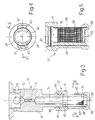
- Number 5 in Figure 1 indicates as a whole a solenoid valve for regulating the fuel supply pressure of an internal combustion engine.
- Solenoid valve 5 comprises a valve body 6 having a supply conduit 7a extending axially along a first cylindrical portion 8 of valve body 6; supply conduit 7a comprises a calibrated-diameter portion 9, and communicates with the delivery side of a high-pressure fuel supply pump not shown; and cylindrical portion 8 is fitted in fluidtight manner to the body of the pump by means of appropriate seals 10.
- Cylindrical portion 8 has a series of radial holes 11 communicating with a drain conduit (not shown) in the pump body. Between supply conduit 7a and radial holes 11, there is provided a shutter in the form of a ball 12, which engages a conical seat 13, formed at the end of portion 9, to close conduit 7a; solenoid valve 5 comprises an electromagnet having a body 15 to which valve body 6 is fitted in known manner; and the electromagnet controls an armature having a stem 16 sliding inside a hole 17 in body 15 and for controlling ball 12.
- the fuel in supply conduit 7a must be kept at an operating pressure of at least 1000 bar.
- the selected operating pressure is about 1400 bar; and the inside diameter of conduit 7a may advantageously be about 2.5 mm.
- supply conduit 7a is provided with fuel filtration means, i.e. a filter comprising a cylindrical wall 22 having one end 23 integral with conduit 7a.
- Wall 22 comprises a number of openings in the form of circular holes 24, only some of which are shown in Figure 1 for the sake of clarity, and which are formed using a laser drilling device. After drilling, the other end 26 of wall 22 is closed by a plug or plate 27 inserted into end 26 in known manner.
- Wall 22 is less than 1 mm, e.g. 0.5 to 0.8 mm, thick; holes 24 are less than 0.25 mm, e.g. 0.05 to 0.08 mm, in diameter; and the surface of wall 22 is such as to house at least 500 holes 24.
- the selected hole diameter is about 0.06 mm, and the selected number of holes 24 is about 2000.
- wall 22 prevents particles of dirt, normally minute metal particles, from infiltrating between conical seat 13 and ball 12, thus preventing sealing problems on solenoid valve 5 which may cause the fuel pressure in conduit 7a to fall so low as to impair operation of the fuel supply system as a whole.
- Holes 24, on the other hand, are such as not to cause an excessive fall in fuel pressure along conduit 7a, and to avoid hydraulic cavitation erosion phenomena. An excessive fall in pressure, in fact, is prevented by drilled wall 22 having just the right ratio between the length of holes 24 and the total passage section.
- the filtration means comprise a cup-shaped body 28 made, for example, of metal; body 28 is separated from the supply conduit 7b and has a cylindrical wall 29 integral with a bottom wall 31; with the exception of an end portion 33, wall 29 is drilled with holes 32 substantially similar to holes 24 in the Figure 1 wall 22; after drilling, body 28 is inserted with end 33 resting on a seat defined by an outer shoulder 34 of conduit 7b; and drilled wall 29 has the same filtering effect as wall 22 in Figure 1.
- the filtration means comprise a cylindrical wall made of netting 36 of wire or other material; and netting 36 is fixed to the conduit 7c by a frame 37 for supporting netting 36, and which is made of plastic material molded on to netting 36 as explained clearly below.
- Netting 36 is of maximum 1 mm thickness and has meshes 38 of 0.05 to 0.08 mm in width so as to contain about 2000 meshes 38.
- the thickness of netting 36 is therefore also such as to achieve the right ratio between the length of meshes 38 and the total passage section and so prevent an excessive fall in pressure.
- Frame 37 comprises a bottom wall 39 ( Figures 3 and 4); a ring 41 which fits on to conduit 7c of valve body 6; and at least two cylindrical sectors 42 integral with bottom wall 39 and ring 41. More specifically, two diametrically opposite cylindrical sectors 42 are provided.
- Netting 36 is fixed to two rings 45 made of sheet metal and which are embedded in ring 41 and wall 39 of frame 37, and two cylindrical sectors 43 of netting 36 are embedded in sectors 42 of frame 37.
- one end 44 ( Figure 3) of conduit 7c has a groove 46, and ring 41 has a projection 47 which clicks into groove 46.
- Netting 36 has the same filtering effect as drilled cylindrical walls 22 and 29.
- the filter may be formed differently or comprise more than one filtering wall located in any position along the supply conduit.
Landscapes
- Engineering & Computer Science (AREA)
- General Engineering & Computer Science (AREA)
- Mechanical Engineering (AREA)
- Chemical & Material Sciences (AREA)
- Combustion & Propulsion (AREA)
- Magnetically Actuated Valves (AREA)
- Fuel-Injection Apparatus (AREA)
Applications Claiming Priority (2)
| Application Number | Priority Date | Filing Date | Title |
|---|---|---|---|
| IT2000TO000143A IT1319838B1 (it) | 2000-02-15 | 2000-02-15 | Perfezionamenti di un'elettrovalvola per la regolazione dellapressione di alimentazione di combustibile ad un motore a combustione |
| ITTO000143 | 2000-02-15 |
Publications (3)
| Publication Number | Publication Date |
|---|---|
| EP1126162A2 true EP1126162A2 (fr) | 2001-08-22 |
| EP1126162A3 EP1126162A3 (fr) | 2002-12-18 |
| EP1126162B1 EP1126162B1 (fr) | 2005-12-28 |
Family
ID=11457424
Family Applications (1)
| Application Number | Title | Priority Date | Filing Date |
|---|---|---|---|
| EP01103448A Expired - Lifetime EP1126162B1 (fr) | 2000-02-15 | 2001-02-14 | Soupape électromagnétique pour la régulation de la pression de combustible d'un moteur à combustion interne |
Country Status (9)
| Country | Link |
|---|---|
| US (1) | US6502553B2 (fr) |
| EP (1) | EP1126162B1 (fr) |
| JP (1) | JP2001254653A (fr) |
| KR (1) | KR100852470B1 (fr) |
| CN (1) | CN1192162C (fr) |
| DE (1) | DE60116157T2 (fr) |
| ES (1) | ES2256095T3 (fr) |
| IT (1) | IT1319838B1 (fr) |
| RU (1) | RU2264556C2 (fr) |
Cited By (6)
| Publication number | Priority date | Publication date | Assignee | Title |
|---|---|---|---|---|
| EP1388666A1 (fr) * | 2002-08-07 | 2004-02-11 | Toyota Jidosha Kabushiki Kaisha | Dispositif d'injection de carburant |
| WO2004020818A1 (fr) * | 2002-08-22 | 2004-03-11 | Siemens Aktiengesellschaft | Injecteur destine a un systeme d'injection de carburant d'un moteur a combustion interne et dispositif de filtrage |
| WO2010023024A1 (fr) * | 2008-09-01 | 2010-03-04 | Robert Bosch Gmbh | Injecteur comportant un filtre à particules disposé en amont du papillon d'admission |
| WO2012076234A1 (fr) * | 2010-12-06 | 2012-06-14 | Robert Bosch Gmbh | Unité de dosage et élément filtrant |
| WO2018069020A1 (fr) * | 2016-10-10 | 2018-04-19 | Robert Bosch Gmbh | Soupape de décharge, en particulier pour une pompe haute pression, ainsi que pompe haute pression et système d'injection de carburant |
| WO2018219548A1 (fr) * | 2017-06-01 | 2018-12-06 | Robert Bosch Gmbh | Pompe à carburant haute pression, et dispositif de filtre à carburant |
Families Citing this family (8)
| Publication number | Priority date | Publication date | Assignee | Title |
|---|---|---|---|---|
| DE10023621A1 (de) * | 2000-05-13 | 2001-11-15 | Bosch Gmbh Robert | Kraftstoffeinspritzsystem für Brennkraftmaschinen |
| DE10222895A1 (de) * | 2002-05-23 | 2003-12-11 | Bosch Gmbh Robert | Hochdruckspeicher für Kraftstoffeinspritzsysteme mit integriertem Druckregelventil |
| DE102008013270A1 (de) * | 2008-03-08 | 2009-09-10 | Robert Bosch Gmbh | Siebfilter und Einbauventil mit Siebfilter |
| EP2535554A1 (fr) * | 2011-06-15 | 2012-12-19 | Delphi Technologies Holding S.à.r.l. | Soupape électrique pour décharger un rail commun |
| HUE025046T2 (en) * | 2012-04-05 | 2016-01-28 | Delphi Int Operations Luxembourg Sarl | valve Assembly |
| US9644589B2 (en) * | 2013-11-20 | 2017-05-09 | Stanadyne Llc | Debris diverter shield for fuel injector |
| KR101729540B1 (ko) | 2015-10-28 | 2017-04-24 | 주식회사 현대케피코 | 공용화 솔레노이드 밸브를 가지는 커먼레일 시스템 |
| US10294901B1 (en) * | 2017-11-20 | 2019-05-21 | Robert Bosch Llc | Vehicle fuel pump module including improved jet pump assembly |
Family Cites Families (20)
| Publication number | Priority date | Publication date | Assignee | Title |
|---|---|---|---|---|
| JPS50220B1 (fr) * | 1970-01-21 | 1975-01-07 | ||
| US3974809A (en) * | 1973-03-16 | 1976-08-17 | Robert Bosch G.M.B.H. | Fuel injection system for spark plug-ignited internal combustion engines with compression of the air-fuel mixture |
| JPS5624108B2 (fr) * | 1974-06-14 | 1981-06-04 | ||
| US4262877A (en) * | 1975-05-09 | 1981-04-21 | Lang Gregor L | Solenoid fluid valves |
| DE3314899A1 (de) * | 1983-04-25 | 1984-10-25 | Mesenich, Gerhard, Dipl.-Ing., 4630 Bochum | Federanordnung mit zusatzmasse zur verbesserung des dynamischen verhaltens von elektromagnetsystemen |
| JPH0670418B2 (ja) * | 1986-03-31 | 1994-09-07 | 日本電装株式会社 | 電磁スピル弁用フイルタ |
| US4981155A (en) * | 1988-09-30 | 1991-01-01 | Eaton Corporation | Electrically operated valve assembly |
| US5510194A (en) * | 1989-07-05 | 1996-04-23 | Alabama Cryogenic Engineering, Inc. | Perforated plate filter media and related products |
| US5114077A (en) * | 1990-12-12 | 1992-05-19 | Siemens Automotive L.P. | Fuel injector end cap |
| DE4131535A1 (de) * | 1991-09-21 | 1993-03-25 | Bosch Gmbh Robert | Elektromagnetisch betaetigbares einspritzventil |
| RU2059868C1 (ru) * | 1992-08-31 | 1996-05-10 | Фирма "Авангард" | Электромагнитная форсунка |
| JP2689226B2 (ja) * | 1994-12-02 | 1997-12-10 | 株式会社ゼクセル | 高圧燃料噴射装置用燃料ポンプ |
| JP3742996B2 (ja) * | 1996-03-25 | 2006-02-08 | 株式会社デンソー | 燃料供給装置 |
| US5913332A (en) * | 1996-12-17 | 1999-06-22 | Caterpillar Inc. | Electronic valve including an edge filter |
| DE19723329A1 (de) * | 1997-06-04 | 1998-12-10 | Bosch Gmbh Robert | Kraftstoffeinspritzsystem für Brennkraftmaschinen |
| JP3872868B2 (ja) * | 1997-06-05 | 2007-01-24 | 株式会社オティックス | 燃料分配管 |
| JPH11107884A (ja) * | 1997-10-01 | 1999-04-20 | Denso Corp | 流量制御装置及びそれを用いた蓄圧式燃料噴射装置 |
| DE19752834A1 (de) * | 1997-11-28 | 1999-06-02 | Bosch Gmbh Robert | Kraftstoffeinspritzeinrichtung für Brennkraftmaschinen |
| KR100637904B1 (ko) * | 1998-03-18 | 2006-10-24 | 미쯔비시 가스 케미칼 컴파니, 인코포레이티드 | 레이저에 의한 관통홀 제조방법 |
| IT247260Y1 (it) * | 1999-09-21 | 2002-05-13 | Elasis Sistema Ricerca Fiat | Perfezionamento di un'elettrovalvola per la regolazione dellapressione di alimentazione di combustibile ad un motore acombustione |
-
2000
- 2000-02-15 IT IT2000TO000143A patent/IT1319838B1/it active
-
2001
- 2001-02-14 KR KR1020010007331A patent/KR100852470B1/ko not_active Expired - Fee Related
- 2001-02-14 EP EP01103448A patent/EP1126162B1/fr not_active Expired - Lifetime
- 2001-02-14 RU RU2001104313/06A patent/RU2264556C2/ru not_active IP Right Cessation
- 2001-02-14 ES ES01103448T patent/ES2256095T3/es not_active Expired - Lifetime
- 2001-02-14 DE DE60116157T patent/DE60116157T2/de not_active Expired - Lifetime
- 2001-02-15 JP JP2001038243A patent/JP2001254653A/ja active Pending
- 2001-02-15 US US09/784,795 patent/US6502553B2/en not_active Expired - Lifetime
- 2001-02-15 CN CNB011116323A patent/CN1192162C/zh not_active Expired - Fee Related
Cited By (7)
| Publication number | Priority date | Publication date | Assignee | Title |
|---|---|---|---|---|
| EP1388666A1 (fr) * | 2002-08-07 | 2004-02-11 | Toyota Jidosha Kabushiki Kaisha | Dispositif d'injection de carburant |
| US6974093B2 (en) | 2002-08-07 | 2005-12-13 | Toyota Jidosha Kabushiki Kaisha | Fuel injection device |
| WO2004020818A1 (fr) * | 2002-08-22 | 2004-03-11 | Siemens Aktiengesellschaft | Injecteur destine a un systeme d'injection de carburant d'un moteur a combustion interne et dispositif de filtrage |
| WO2010023024A1 (fr) * | 2008-09-01 | 2010-03-04 | Robert Bosch Gmbh | Injecteur comportant un filtre à particules disposé en amont du papillon d'admission |
| WO2012076234A1 (fr) * | 2010-12-06 | 2012-06-14 | Robert Bosch Gmbh | Unité de dosage et élément filtrant |
| WO2018069020A1 (fr) * | 2016-10-10 | 2018-04-19 | Robert Bosch Gmbh | Soupape de décharge, en particulier pour une pompe haute pression, ainsi que pompe haute pression et système d'injection de carburant |
| WO2018219548A1 (fr) * | 2017-06-01 | 2018-12-06 | Robert Bosch Gmbh | Pompe à carburant haute pression, et dispositif de filtre à carburant |
Also Published As
| Publication number | Publication date |
|---|---|
| CN1310294A (zh) | 2001-08-29 |
| ITTO20000143A1 (it) | 2001-08-15 |
| RU2264556C2 (ru) | 2005-11-20 |
| US20010029930A1 (en) | 2001-10-18 |
| US6502553B2 (en) | 2003-01-07 |
| CN1192162C (zh) | 2005-03-09 |
| JP2001254653A (ja) | 2001-09-21 |
| KR20010082636A (ko) | 2001-08-30 |
| ES2256095T3 (es) | 2006-07-16 |
| EP1126162A3 (fr) | 2002-12-18 |
| EP1126162B1 (fr) | 2005-12-28 |
| IT1319838B1 (it) | 2003-11-03 |
| DE60116157D1 (de) | 2006-02-02 |
| DE60116157T2 (de) | 2006-08-17 |
| KR100852470B1 (ko) | 2008-08-18 |
Similar Documents
| Publication | Publication Date | Title |
|---|---|---|
| EP1126162B1 (fr) | Soupape électromagnétique pour la régulation de la pression de combustible d'un moteur à combustion interne | |
| US5727525A (en) | Accumulator fuel injection system | |
| EP0136815B1 (fr) | Combiné pompe-injecteur à commande électromagnétique | |
| EP1041272B1 (fr) | Injecteur de combustible | |
| DE60022589T2 (de) | Vorrichtung zur Regelung des Abgabedruckes einer Pumpe,zum Beispiel zum Fördern von Kraftstoff zu einem Verbrennungsmotor | |
| CN101165334B (zh) | 用于控制内燃机用燃料泵的流量的截止阀 | |
| EP0916842A1 (fr) | Dispositif de commande d'un injecteur de combustible de moteurs à combustion interne | |
| US6672290B2 (en) | Internal combustion engine common-rail injection system with a fuel premetering device | |
| EP0385399B1 (fr) | Injecteur électromagnétique de carburant pour moteur diesel | |
| EP0124191B1 (fr) | Injecteur électromagnétique de carburant de type unifié avec soupape de type à insertion actionnée par solénoide | |
| US6308689B1 (en) | Injection valve for an internal combustion engine | |
| US20050241616A1 (en) | Fuel injection device for an internal combustion engine | |
| EP1136692A2 (fr) | Injecteur de carburant avec une aiguille de contrôle commandée par la pression du carburant dans une chambre de commande | |
| RU2262617C2 (ru) | Устройство впрыскивания топлива со встроенным ограничением расхода | |
| EP1087131B1 (fr) | Electrovanne régulant la pression de carburant dans un système d'injection de machine à combustion interne | |
| EP1081373A3 (fr) | Injecteur à combustible | |
| KR100714855B1 (ko) | 분사 시스템 | |
| EP0987432A3 (fr) | Injecteur de combustible | |
| EP0385398A2 (fr) | Injecteur électromagnétique de carburant pour moteur diesel | |
| US6565013B1 (en) | Common rail injector | |
| EP1065368A2 (fr) | Injecteur de carburant | |
| US20160160820A1 (en) | Injector arrangment | |
| EP1143139A1 (fr) | Système d'alimentation en combustible | |
| US20090173316A1 (en) | Injection means for a combustion engine | |
| JP3568636B2 (ja) | ソレノイド駆動油圧制御弁 |
Legal Events
| Date | Code | Title | Description |
|---|---|---|---|
| PUAI | Public reference made under article 153(3) epc to a published international application that has entered the european phase |
Free format text: ORIGINAL CODE: 0009012 |
|
| AK | Designated contracting states |
Kind code of ref document: A2 Designated state(s): AT BE CH CY DE DK ES FI FR GB GR IE IT LI LU MC NL PT SE TR |
|
| AX | Request for extension of the european patent |
Free format text: AL;LT;LV;MK;RO;SI |
|
| PUAL | Search report despatched |
Free format text: ORIGINAL CODE: 0009013 |
|
| AK | Designated contracting states |
Kind code of ref document: A3 Designated state(s): AT BE CH CY DE DK ES FI FR GB GR IE IT LI LU MC NL PT SE TR |
|
| AX | Request for extension of the european patent |
Free format text: AL;LT;LV;MK;RO;SI |
|
| RIC1 | Information provided on ipc code assigned before grant |
Free format text: 7F 02M 63/02 A, 7F 02M 59/46 B |
|
| 17P | Request for examination filed |
Effective date: 20030616 |
|
| 17Q | First examination report despatched |
Effective date: 20030721 |
|
| AKX | Designation fees paid |
Designated state(s): DE ES FR GB IT SE |
|
| GRAP | Despatch of communication of intention to grant a patent |
Free format text: ORIGINAL CODE: EPIDOSNIGR1 |
|
| GRAS | Grant fee paid |
Free format text: ORIGINAL CODE: EPIDOSNIGR3 |
|
| GRAA | (expected) grant |
Free format text: ORIGINAL CODE: 0009210 |
|
| AK | Designated contracting states |
Kind code of ref document: B1 Designated state(s): DE ES FR GB IT SE |
|
| REG | Reference to a national code |
Ref country code: GB Ref legal event code: FG4D |
|
| REF | Corresponds to: |
Ref document number: 60116157 Country of ref document: DE Date of ref document: 20060202 Kind code of ref document: P |
|
| REG | Reference to a national code |
Ref country code: SE Ref legal event code: TRGR |
|
| REG | Reference to a national code |
Ref country code: ES Ref legal event code: FG2A Ref document number: 2256095 Country of ref document: ES Kind code of ref document: T3 |
|
| ET | Fr: translation filed | ||
| PLBE | No opposition filed within time limit |
Free format text: ORIGINAL CODE: 0009261 |
|
| STAA | Information on the status of an ep patent application or granted ep patent |
Free format text: STATUS: NO OPPOSITION FILED WITHIN TIME LIMIT |
|
| 26N | No opposition filed |
Effective date: 20060929 |
|
| PGFP | Annual fee paid to national office [announced via postgrant information from national office to epo] |
Ref country code: SE Payment date: 20091222 Year of fee payment: 10 |
|
| PGFP | Annual fee paid to national office [announced via postgrant information from national office to epo] |
Ref country code: ES Payment date: 20100219 Year of fee payment: 10 |
|
| PGFP | Annual fee paid to national office [announced via postgrant information from national office to epo] |
Ref country code: GB Payment date: 20100219 Year of fee payment: 10 |
|
| REG | Reference to a national code |
Ref country code: SE Ref legal event code: EUG |
|
| GBPC | Gb: european patent ceased through non-payment of renewal fee |
Effective date: 20110214 |
|
| PG25 | Lapsed in a contracting state [announced via postgrant information from national office to epo] |
Ref country code: GB Free format text: LAPSE BECAUSE OF NON-PAYMENT OF DUE FEES Effective date: 20110214 |
|
| REG | Reference to a national code |
Ref country code: ES Ref legal event code: FD2A Effective date: 20120411 |
|
| PG25 | Lapsed in a contracting state [announced via postgrant information from national office to epo] |
Ref country code: ES Free format text: LAPSE BECAUSE OF NON-PAYMENT OF DUE FEES Effective date: 20110215 |
|
| PG25 | Lapsed in a contracting state [announced via postgrant information from national office to epo] |
Ref country code: SE Free format text: LAPSE BECAUSE OF NON-PAYMENT OF DUE FEES Effective date: 20110215 |
|
| PGFP | Annual fee paid to national office [announced via postgrant information from national office to epo] |
Ref country code: IT Payment date: 20140224 Year of fee payment: 14 |
|
| PG25 | Lapsed in a contracting state [announced via postgrant information from national office to epo] |
Ref country code: IT Free format text: LAPSE BECAUSE OF NON-PAYMENT OF DUE FEES Effective date: 20150214 |
|
| REG | Reference to a national code |
Ref country code: FR Ref legal event code: PLFP Year of fee payment: 16 |
|
| REG | Reference to a national code |
Ref country code: FR Ref legal event code: PLFP Year of fee payment: 17 |
|
| PGFP | Annual fee paid to national office [announced via postgrant information from national office to epo] |
Ref country code: FR Payment date: 20170220 Year of fee payment: 17 |
|
| REG | Reference to a national code |
Ref country code: FR Ref legal event code: ST Effective date: 20181031 |
|
| PG25 | Lapsed in a contracting state [announced via postgrant information from national office to epo] |
Ref country code: FR Free format text: LAPSE BECAUSE OF NON-PAYMENT OF DUE FEES Effective date: 20180228 |
|
| PGFP | Annual fee paid to national office [announced via postgrant information from national office to epo] |
Ref country code: DE Payment date: 20200421 Year of fee payment: 20 |
|
| REG | Reference to a national code |
Ref country code: DE Ref legal event code: R071 Ref document number: 60116157 Country of ref document: DE |