EP1126176A2 - Elektrisch angetriebene, doppelseitig saugende Pumpe - Google Patents
Elektrisch angetriebene, doppelseitig saugende Pumpe Download PDFInfo
- Publication number
- EP1126176A2 EP1126176A2 EP01102658A EP01102658A EP1126176A2 EP 1126176 A2 EP1126176 A2 EP 1126176A2 EP 01102658 A EP01102658 A EP 01102658A EP 01102658 A EP01102658 A EP 01102658A EP 1126176 A2 EP1126176 A2 EP 1126176A2
- Authority
- EP
- European Patent Office
- Prior art keywords
- output shaft
- motor
- electric motor
- pump housing
- end portion
- Prior art date
- Legal status (The legal status is an assumption and is not a legal conclusion. Google has not performed a legal analysis and makes no representation as to the accuracy of the status listed.)
- Withdrawn
Links
Images




Classifications
-
- F—MECHANICAL ENGINEERING; LIGHTING; HEATING; WEAPONS; BLASTING
- F04—POSITIVE - DISPLACEMENT MACHINES FOR LIQUIDS; PUMPS FOR LIQUIDS OR ELASTIC FLUIDS
- F04D—NON-POSITIVE-DISPLACEMENT PUMPS
- F04D3/00—Axial-flow pumps
- F04D3/02—Axial-flow pumps of screw type
-
- F—MECHANICAL ENGINEERING; LIGHTING; HEATING; WEAPONS; BLASTING
- F04—POSITIVE - DISPLACEMENT MACHINES FOR LIQUIDS; PUMPS FOR LIQUIDS OR ELASTIC FLUIDS
- F04D—NON-POSITIVE-DISPLACEMENT PUMPS
- F04D13/00—Pumping installations or systems
-
- F—MECHANICAL ENGINEERING; LIGHTING; HEATING; WEAPONS; BLASTING
- F04—POSITIVE - DISPLACEMENT MACHINES FOR LIQUIDS; PUMPS FOR LIQUIDS OR ELASTIC FLUIDS
- F04D—NON-POSITIVE-DISPLACEMENT PUMPS
- F04D1/00—Radial-flow pumps, e.g. centrifugal pumps; Helico-centrifugal pumps
- F04D1/006—Radial-flow pumps, e.g. centrifugal pumps; Helico-centrifugal pumps double suction pumps
-
- F—MECHANICAL ENGINEERING; LIGHTING; HEATING; WEAPONS; BLASTING
- F04—POSITIVE - DISPLACEMENT MACHINES FOR LIQUIDS; PUMPS FOR LIQUIDS OR ELASTIC FLUIDS
- F04D—NON-POSITIVE-DISPLACEMENT PUMPS
- F04D13/00—Pumping installations or systems
- F04D13/02—Units comprising pumps and their driving means
- F04D13/06—Units comprising pumps and their driving means the pump being electrically driven
-
- F—MECHANICAL ENGINEERING; LIGHTING; HEATING; WEAPONS; BLASTING
- F04—POSITIVE - DISPLACEMENT MACHINES FOR LIQUIDS; PUMPS FOR LIQUIDS OR ELASTIC FLUIDS
- F04D—NON-POSITIVE-DISPLACEMENT PUMPS
- F04D29/00—Details, component parts, or accessories
- F04D29/18—Rotors
- F04D29/22—Rotors specially for centrifugal pumps
- F04D29/2261—Rotors specially for centrifugal pumps with special measures
- F04D29/2277—Rotors specially for centrifugal pumps with special measures for increasing NPSH or dealing with liquids near boiling-point
Definitions
- the present invention relates to a motor-driven pump with a plurality of impellers.
- a motor-driven pump of this type is used to increase a discharge amount of fluid discharged therefrom and known from, for example, Japanese Patent Application KOKAI Publication No. 58-8295.
- the motor driven pump described in the Publication No. 58-8295 comprises an electric motor and a pump unit having a rotational center shaft coupled to the output shaft of the electric motor. Both end portions of the rotational center shaft of the pump unit are rotatably supported by both side walls of a pump housing through a pair of bearings, and a pair of impellers are fixed to a central portion of the center shaft in its longitudinal direction.
- the paired impellers have a pair of fluid inlet regions opening toward the both end portions of the central shaft from the neighborhood of the longitudinal center portion of the rotational center shaft in an inner space of the pump housing, and one fluid discharge region opening outward in a radial direction of the rotational center shaft from the neighborhood of the central portion.
- a pair of fluid channels from the paired fluid inlet regions toward the one fluid discharge region are joined together in the vicinity of the fluid discharge region.
- a spiral shaped chamber is formed in a portion facing the fluid discharge region of the paired impellers.
- An outlet of the spiral shaped chamber is connected to a conduit, not shown, and a distal end of this conduit reaches a position to which fluid is to be moved by this motor-driven pump.
- fluid to be moved by this motor-driven pump is flowed into on the both side portions of the paired impellers through conduits not shown.
- one of the bearings is a radial bearing and the other is a radial-thrust bearing.
- the thrust bearing disadvantageously complicates a constitution of the pump unit, increases an outside dimension thereof, and increases its weight and manufacturing cost thereof.
- the present invention has been derived from these circumstances. It is, therefore, an object of the present invention to provide a motor-driven pump having a plurality of impellers, capable of dispensing with a thrust bearing for a high thrust force, simple in constitution, small in outer dimension, small in weight and low in manufacturing cost.
- a motor-driven pump with a plurality of impellers comprises:
- the motor-driven pump with a plurality of impellers according to the present invention dispenses with a thrust bearing for a high thrust force, is simple in constitution, small in outer dimension, small in weight and low in manufacturing cost.
- a radial bearing rotatably supporting the other end portion of the output shaft can be provided in an opposite portion to the pump housing in the motor frame of the electric motor; and another radial bearing rotatably supporting the one end portion of the output shaft can be provided in a portion adjacent the pump housing in the motor frame of the electric motor.
- a radial bearing rotatably supporting the other end portion of the output shaft can be provided in an opposite portion to the pump housing in the motor frame of the electric motor; and another radial bearing rotatably supporting the one end portion of the output shaft can be provided in a portion, located outward from the one end portion in the longitudinal direction of the output shaft, in the pump housing of the electric motor.
- the fluid inlet port region on the side away from the electric motor can open outward in the longitudinal direction of the one end portion of the output shaft; and in the pump housing, the fluid inlet port region on the side adjacent the electric motor can open outward in the radial direction of the output shaft.
- the one fluid discharge port region of the pump housing has a plurality of fluid discharge ports; and that the plurality of fluid discharge ports are arranged equidistantly in a circumferential direction of the one end portion of the output shaft.
- the extending ends of the plurality of fluid discharge ports can be integrated into one end.
- another motor-driven pump with a plurality of impellers comprises:
- Another motor-driven pump with a plurality of impellers described above and according to the present invention dispenses with a thrust bearing for a high thrust force, is simple in constitution, small in outer dimension, small in weight and low in production cost.
- fluid can be supplied to the electric motor side on the partition wall in the inner space of the pump housing by the axial-flow impeller unit of the electric motor. Therefore, this invention can reduce a capacity of the electric motor side on the partition wall in the inner space of the pump housing and reduce the dimension of the pump housing in the direction along the output shaft (i.e., the dimension of the motor-driven motor of this invention in the above direction) without deteriorating the performance of the motor-driven pump according to this invention such as discharge amount and discharge pressure of fluid discharged therefrom.
- a radial bearing rotatably supporting the other end portion of the output shaft can be provided in an opposite portion to the pump housing in the motor frame of the electric motor; and another radial bearing rotatably supporting the one end portion of the output shaft can be provided in a portion adjacent the pump housing in the motor frame of the electric motor.
- the rotation driving mechanism of the electric motor includes a rotor fixed to the output shaft in the inner space of the motor frame, and a stator opposite to the rotor in a radial direction of the output shaft in the motor frame; a concave portion elongated in the longitudinal direction of the rotor is formed on an outer peripheral surface of the rotor, a circumferential position of the concave portion deviated while extending in the longitudinal direction of the output shaft; and the rotor having the concave portion constitutes the axial-flow impeller unit.
- the axial-flow impeller unit thus constituted is simple and compact in constitution and easy to manufacture.
- the fluid inlet port region on the side away from the electric motor opens outward in the longitudinal direction of the one end portion of the output shaft; and that in the pump housing, the fluid inlet port region on the side adjacent the electric motor opens toward the electric motor in the longitudinal direction of the output shaft.
- the axial-flow impeller unit can efficiently feed fluid into the fluid inlet port region in such a pump housing from the pump housing communication port region of the motor frame of the electric motor.
- the one fluid discharge port region of the pump housing has a plurality of fluid discharge ports; and the plurality of fluid discharge ports are arranged equidistantly in a circumferential direction of the one end portion of the output shaft.
- the extending ends of the plurality of fluid discharge ports can be integrated into one end.
- a portion adjacent the pump housing around the output shaft and exposed to the pump housing communication port region in the motor frame is inclined inward in the radial direction of the output shaft as the portion is closer to the partition wall of the impeller unit.
- the axial-flow impeller unit can efficiently feed fluid into the fluid inlet port region in such a pump housing from the pump housing communication port region of the motor frame of the electric motor.
- a radial bearing rotatably supporting the other end portion of the output shaft can be provided in an opposite portion to the pump housing in the motor frame of the electric motor; and another radial bearing rotatably supporting the one end portion of the output shaft can be provided in a portion, located outward from the one end portion in the longitudinal direction of the output shaft, in the pump housing of the electric motor.
- the rotation driving mechanism of the electric motor includes a rotor fixed to the output shaft in the inner space of the motor frame, and a stator opposite to the rotor outward in the radial direction of the output shaft in the motor frame, a concave portion elongated in the longitudinal direction of the rotor is formed on an outer peripheral surface of the rotor, a circumferential position of the concave portion deviated while extending in the longitudinal direction of the output shaft and the rotator having the concave portion constitutes the axial-flow impeller unit, then it is preferable that a portion of the rotor adjacent the pump housing around the output shaft is exposed to the pump housing communication port region of the motor frame, and inclined inward in the radial direction of the output shaft as the portion is closer to the partition wall of the impeller unit.
- the axial-flow impeller unit can efficiently feed fluid into the fluid inlet port region in such a pump housing fluid from the pump housing communication port region of the motor frame of the electric motor.
- yet another motor-driven pump with a plurality of impellers comprises:
- yet another motor-driven pump with a plurality of impellers described above and according to the present invention dispenses with a thrust bearing for a high thrust force, is simple in constitution, small in outer dimension, small in weight and low in production cost.
- the fluid can be supplied to the electric motor side on the partition wall in the inner space of the pump housing by the axial-flow impeller unit of the electric motor. Therefore, this invention can reduce a capacity of the electric motor side on the partition wall in the inner space of the pump housing, and further, since the blade means is not provided on the electric motor side on the partition wall, this invention can reduce the dimension of the pump housing in the direction along the output shaft (i.e., the dimension of the motor-driven motor of this invention in the above direction), without deteriorating the performance of the motor-driven pump according to this invention such as discharge amount and discharge pressure of fluid discharged therefrom or even if the performance is to be improved.
- a radial bearing rotatably supporting the other end portion of the output shaft can be provided in an opposite portion to the pump housing in the motor frame of the electric motor; and another radial bearing rotatably supporting the one end portion of the output shaft can be provided in a portion, located outward from the one end portion of the output shaft in the longitudinal direction in the pump housing.
- the rotation driving mechanism of the electric motor includes a rotor fixed to the output shaft in the inner space of the motor frame, and a stator opposite to the rotor in a radial direction of the output shaft in the motor frame; a concave portion elongated in the longitudinal direction of the rotor is formed on an outer peripheral surface of the rotor, a circumferential position of the concave portion deviated while extending to the longitudinal direction of the output shaft; and the rotor having the concave portion constitutes the axial-flow impeller unit.
- the axial-flow impeller unit thus constituted is simple and compact in constitution and easy to manufacture.
- the fluid inlet port region on the side away from the electric motor opens outward in the longitudinal direction of the one end portion of the output shaft; and that in the pump housing, the fluid inlet port region on the side adjacent the electric motor opens toward the electric motor in the longitudinal direction of the output shaft.
- the axial-flow impeller unit can efficiently feed fluid into the fluid inlet port region of the pump housing from the pump housing communication port region of the motor frame of the electric motor.
- the one fluid discharge port region of the pump housing has a plurality of fluid discharge ports, and the plurality of fluid discharge ports are arranged equidistantly in a circumferential direction of the one end portion of the output shaft, this can reduce the radial forces applied to the output shaft and reduce the outer dimension and manufacturing cost of yet another motor-driven pump according to this invention as stated above in the case of the motor-driven pump according to this invention and another motor-driven pump according to this invention.
- the extending ends of the plurality of fluid discharge ports can be integrated into one end.
- FIG. 1 is a longitudinal sectional view showing a constitution of a motor-driven pump according to a first embodiment of the present invention.
- This motor-driven pump includes an electric motor 1 and a pump unit 2.
- the electric motor 1 has a rotor 7 and a cylindrical stator 3 in an inner space of which the rotor 7 is arranged.
- the stator 3 has a stator core 4 having six magnetic poles arranged at intervals of 60° in a circumferential direction of the core 4.
- An exciting winding 5 is wound around the stator core 4.
- An insulating resion such as polyester are molded on the stator core 4 and the exciting winding 5 to surround cylindrically them and to make the stator 3 waterproof.
- Both end openings of the stator 3 are watertightly covered with motor frames 8, 9.
- the rotor 7 has four poles coaxially fixed to an output shaft 6, and the shaft 6 is rotatably supported by a pair of radial bearings 10, 11 on the motor frames 8, 9.
- the stator 3 and rotor 7 constitute a three-phase motor.
- One end portion of the output shaft 6 protrudes outward from the frame 8 and a female screw is formed on the tip end of the one end portion.
- the pump unit 2 is arranged on the motor frame 8.
- the pump unit 2 includes a disk-shaped partition wall 12 coaxially fitted on the tip end of the one end portion of the output shaft 6, and the partition wall 12 is fixed on the tip end by screwing a nut 113 on the bolt on the tip end.
- Six blades 14 are arranged on each of both side surfaces of the partitions wall 12 at equiangular intervals, and forms oblique plates 15, thereby forming two centrifugal impellers 16 on the both side surfaces of the partition wall 12.
- the pump unit 2 further includes a pump housing 17 which surrounds the centrifugal impellers 16 and one end of which is fixed to the frame 8 of the electric motor 1.
- the pump housing 17 has two fluid inlet port regions 18 and 19 formed on both sides of the partition wall 12 and one fluid outlet port region formed between the two inlet port regions 18 19.
- the fluid outlet port region has two fluid discharge ports 20 and 21 arranged at equiangular intervals, i.e., at intervals of 180°, in a circumferential direction of the housing 17.
- One fluid inlet port region 18 located at a position away from the motor 1 opens outward in a longitudinal direction of the one end portion of the shaft 6, and the other fluid inlet port region 19 located at a position near the motor frame 8 of the motor 1 opens toward the motor frame 8.
- the other inlet port 19 is communicated with an outer space through an opening region in the frame 8, and the opening region has a plurality of ports orientated outward in a radial direction of the shaft 6 and arranged equidistantly in a circumferential direction of the shaft 6.
- FIG. 2A is a cross-sectional view taken along a line IIA-IIA of FIG. 1
- FIG. 2B is a cross-sectional view taken along a line IIB-IIB of FIG. 1.
- the pump housing 2 has two spiral shaped chambers 22 and 23 at positions corresponding to radially outward ends of the impellers 16 on the partition wall 12. Outer ends of the spiral shaped chamber 22 and 23 are communicated with the discharge parts 20, 21.
- the motor-driven pump constituted as described above is sunk in a fluid, for example, a water and the three phase alternating currents are supplied to the electric motor 1 so that the output shaft 6 rotates in a predetermined direction.
- an impeller unit having two impellers 16 rotates in the predetermined direction. While the impellers 16 rotates as described above, the fluids in the impellers 16 are given Kinetic energy by the Centrifugal force to move radially outward and are discharged into the spiral shaped chambers 22, 23. The discharged fluids are decelerated and its pressure is increased in the spiral shaped chambers 22, 23, and they are finally discharged out from the discharge ports 20, 21. At the same time, fluid located around the pump is sucked through the two fluid inlet port regions 18, 19 as indicated by arrows and reaches at the radial center portions of the impellers 16 on the both sides of the partition walls 12.
- the inlet ports 18 and 19 are provided on the both sides of the pump housing 17 in the longitudinal direction of the output shaft 6 and fluid is sucked into the radial center portions of the impellers 16 along the longitudinal direction of the output shaft 6.
- thrust loads applied to the output shaft 6 through the impeller unit during the rotation of the impellers 16 cancel each other. It is, therefore, possible to decrease the thrust load on the output shaft 6, to dispose with a thrust bearing for a high thrust load and to make the bearings 10, 11 simple in constitution and small in size.
- the motor-driven pump of this embodiment is used as a high lift pump, the thrust load is stable and light, and eccentric abrasion of the bearing generated by the unstable radial load is decreased, so that abrasion of sliding portions in the pump is greatly decreased. Besides, vibration and noise generated in the pump are reduced.
- the pump housing 17 has two spiral shaped chambers 22 and 23 corresponding to the two impellers 16 on the both sides of the partition wall 112, and has the two discharge ports 20 and 21 communicated with the spiral shaped chambers 22 and 23 and arranged at intervals of 180° in the circumferential direction of the housing 17.
- the constitution of the pump unit 2 should not be limited to that described above.
- a pump unit having a common spiral shaped chamber 24 formed in a pump housing to correspond to two impellers 16 on both side surfaces of a partition wall 12, and having two discharge ports 20 and 21 communicated with the common chamber 24 may be used.
- a pump unit having a common spiral shaped chamber 25 formed in a pump housing to correspond to two impellers 16 on both side surfaces of a partition wall 12, and having three discharge ports 26, 27 and 28 communicated with the scroll chamber 25 and arranged at intervals of 120° may be used.
- each of the impellers 16 should not be limited to that of this embodiment and the shapes of the blades 14 may be variably modified.
- a water tight seal 29 is provided, instead of the bearing 10, on the motor frame 8 of the electric motor 1, and a radial bearing 30 is provided on a part of the pump housing 17 located away from the motor 1 than the impeller unit.
- the output shaft 6 is rotatably and watertightly projected outward from the motor frame 8 and the tip end of the shaft 6 is rotatably supported by this bearing 30.
- the impeller unit is located near the motor 1 than the bearing 30.
- the motor-driven pump of this second embodiment can exhibit the same advantages as those in the first embodiment. Sine no water is introduced into the inner space of the motor, there is no need to apply a water protection to the windings, so that no friction loss generated by water between the rotor and the stator and the efficiency of the motor is improved.
- FIG. 6 a constitution of a pump housing 17 of a pump unit 32 is different from that of the pump unit 2 in the first embodiment described above.
- FIG. 7A is a cross-sectional view of the pump housing 17 of this pump unit 32 taken along line VIIA-VIIA of FIG. 6, and
- FIG. 7B is a cross-sectional view of the pump housing 17 of this pump unit 32 taken along line VIIB-VIIB of FIG. 6.
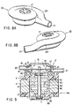
- FIG. 8A is a perspective view of the pump housing 17 of the pump unit 32, and FIG. 8B is a perspective view thereof but it is viewed from an opposite side to that of FIG. 8B. As shown in FIGS.
- one of the two spiral shaped chambers is extended to surround an outer circumferential surface of the pump housing 17, and one discharge port 201 of the one spiral shaped chamber is joined to the other discharge port 21 at a connection point 33.
- a centrifugal impeller unit having two impellers 16 housed in a pump housing 17 of a pump unit 2 is used in combination with an axial-flow impeller unit 44 housed in an inner space of a startor 3 of an electric motor 40.
- a rotor 41 of the electric motor 40 arranged in the stator 3 has four poles 42 radially outwardly projecting from the output shaft 6. These poles 42 are shifted at an interval of 90° in the circumferential direction of the shaft 6 and alternatively magnetized in different magnetic poles.
- a plastic is molded on these poles 42 to have a cylindrical shape.
- An elongated concave 43 is provided on an outer peripheral surface of the cylindrical plastic to deflect in a circumferential direction of the cylindrical plastic while the concave extends in the longitudinal direction of the output shaft 6, thereby forming the axial-flow impeller unit 44 with the spiral shaped concave 43.
- the electric motor 40 has a motor frame 45 fixed to the one-end side of the startor 3 near the pump unit 2 and a motor frame 46 fixed to the other end-side away from the pump unit 2. Radial bearings 10 and 11 rotatably supporting the output shaft 6 are provided on the frames 45 and 46, respectively.
- Openings communicated with the inner space of the stator 3 are formed in the motor frames 45 and 46.
- the opening of the frame 45 is orientated in the longitudinal direction of the shaft 6 toward the fluid inlet port region 19 of the pump housing 17 near the motor 40 and is used as a pump housing communication port 47.
- the opening of the frame 46 orientated toward the outer space in the longitudinal direction of the shaft 6 and is used as an external communication port region 48.
- the spiral shaped concave 43 formed in the outer peripheral surface of the rotor 41 works together with an inner peripheral surface of the stator 3 to transfer fluid introduced into the inner space of the stator 3 through the external communication port region 48 toward the pump housing communication port region 47 in the longitudinal direction. Also, by changing a width, depth, tilt angle, spiral pitch and the like of the spiral shaped concave 43, a performance of the axial flow impeller unit 44 can be changed.
- the axial-flow impeller unit 44 mainly constituted by the rotor 41 of the electric motor 40, cooperates with the centrifugal impellers 16 so that the performance of the pump can be improved further.
- the two fluid discharge ports 20 and 21 are arranged in the outer circumferential direction of the output shaft 6 at intervals of 180° . Due to this, radial loads applied to the output shaft 6 during the rotation of the impeller unit cancel each other, whereby the radial loads applied on the output shaft 6 are reduced.
- both the thrust loads and the radial loads applied to the output shaft 6 is reduced and the radial bearing 10, 11 can be made simpler in constitution and smaller in size.
- the thrust load is stable and light and eccentric abrasion generated by the unstable radial load is decreased, so that abrasion of sliding portions in the pump is greatly decreased. Besides, vibration and noise generated in the pump are reduced.
- an additional fluid inlet port region 50 is provided in the motor frame 45 located near to the pump housing 17.
- the additional fluid inlet port region 50 opens in the radial direction of the output shaft 6, and fluid is also sucked from this addition fluid inlet port region 50 into the fluid inlet port region 19 near the motor 40 in the pump housing 17.
- a constitution of a pump housing 17 of a pump unit 32 is different from that of the pump unit 2 in the above-described fifth embodiment described above.
- the pump housing 17 of this pump unit 32 has the same shape as that of the pump unit 32 in the above-described third embodiment shown in FIG. 6.
- One of the two spiral shaped chambers is extended to surrounding an outer circumferential surface of the pump housing 17, and one discharge port 201 of the one spiral shaped chamber is joined to the other discharge port 21 at a connection point 33.
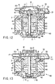
- a radial bearing 30 is provided on a portion of the pump housing 17 located away from the motor 40 than the impeller unit, and the tip end of the shaft 6 is rotatably supported by this bearing 30.
- the pump housing 17 is directly fixed to the one-end side of the stator 3 of the electric motor 40.
- One end potion 51 of a rotor 52 projected in the fluid inlet port region 19 of the pump housing 17 is formed to have a semicircular circumferential surface.
- the semicircular circumferential surface is surrounded by the fluid inlet port region 19 and is inclined radially inward as it approaches to the partition wall 12 in the longitudinal direction of the output shaft 6.
- a radial bearing 30 is provided on a portion of the pump housing 17 located away from the motor 40 than the impeller unit, and the tip end of the shaft 6 is rotatably supported by this bearing 30.
- the pump housing 17 is directly fixed to the one-end side of the stator 3 of the electric motor 40.
- One end potion 53 of a rotor 54 projected in the fluid inlet port region 19 of the pump housing is tapered such that it is inclined inward as it approaches to the partition wall 12 in the longitudinal direction of the output shaft 6.
- a radial bearing 30 is provided on a portion of the pump housing 17 located away from the motor 40 than the impeller unit, and the tip end of the shaft 6 is rotatably supported by this bearing 30.
- the pump housing 17 is directly fixed to the one-end side of the stator 3 of the electric motor 40.
- an impeller unit of a pump unit 62 of this embodiment has a plurality of blades 14 only on one side of a partition wall 12 located away from the motor 40 so that a centrifugal impeller 61 is provided only on the one side of the partition wall 12.
- an end potion 63 of a rotor 64 projected into the fluid inlet port region 19 of the pump housing 17 located near the motor 40 is abutted against a side surface of the partition wall 12 located near the electric motor 40. Further, an outer circumferential surface of the end portion 63 of the rotor 64 is tapered such that it is away from the shaft 6 while it approaches the partition wall 12.
- fluid sucked from the fluid inlet port region 18 provided on the position away from the motor 40 in the pump housing 17 by the rotation of the centrifugal impeller 61 is transferred into the spiral shaped chamber and reaches at the fluid outlet port 21 through the fluid outlet port 201 joined to the fluid outlet port 21 at the connection point 33.
- fluid sucked from the external communication port 48 of the motor 40 located away from the pump unit 62 is transferred by the rotation of an axial-flow impeller unit 44 to the fluid inlet port region 19 provided on the position near the motor 40 in the pump housing 17 through the pump housing communication port 47 of the motor 40.
- the fluid transferred into the fluid inlet port region 19 is further flown into another spiral shaped chamber and reaches at the fluid outlet port 21.
- the centrifugal impeller 16 is formed on each of the both sides or one side of the partition wall 12. It is also possible, however, that the partition wall 12 is vertically dividable on a division surface orthogonal to the output shaft 6 and that the centrifugal impeller 16 is formed on each of the two vertically dividable partition wall halves.
Landscapes
- Engineering & Computer Science (AREA)
- Mechanical Engineering (AREA)
- General Engineering & Computer Science (AREA)
- Structures Of Non-Positive Displacement Pumps (AREA)
- Connection Of Motors, Electrical Generators, Mechanical Devices, And The Like (AREA)
Applications Claiming Priority (4)
| Application Number | Priority Date | Filing Date | Title |
|---|---|---|---|
| JP2000033527 | 2000-02-10 | ||
| JP2000033527 | 2000-02-10 | ||
| JP2000380350 | 2000-12-14 | ||
| JP2000380350A JP3475174B2 (ja) | 2000-02-10 | 2000-12-14 | 電動ポンプ |
Publications (2)
| Publication Number | Publication Date |
|---|---|
| EP1126176A2 true EP1126176A2 (de) | 2001-08-22 |
| EP1126176A3 EP1126176A3 (de) | 2003-11-26 |
Family
ID=26585200
Family Applications (1)
| Application Number | Title | Priority Date | Filing Date |
|---|---|---|---|
| EP01102658A Withdrawn EP1126176A3 (de) | 2000-02-10 | 2001-02-07 | Elektrisch angetriebene, doppelseitig saugende Pumpe |
Country Status (5)
| Country | Link |
|---|---|
| US (1) | US6514053B2 (de) |
| EP (1) | EP1126176A3 (de) |
| JP (1) | JP3475174B2 (de) |
| KR (1) | KR100426668B1 (de) |
| CN (1) | CN1193170C (de) |
Cited By (3)
| Publication number | Priority date | Publication date | Assignee | Title |
|---|---|---|---|---|
| DE102008013675A1 (de) * | 2008-03-11 | 2009-09-17 | Dr. Ing. H.C. F. Porsche Aktiengesellschaft | Kühlmediumpumpe |
| EP2397700A3 (de) * | 2010-06-18 | 2013-01-23 | Sulzer Pumpen Ag | Spiralförmiges Pumpengehäuse für eine Zentrifugalpumpe |
| EP3646440B1 (de) * | 2017-06-30 | 2023-09-13 | Tesla, Inc. | Elektropumpensystem und -verfahren |
Families Citing this family (56)
| Publication number | Priority date | Publication date | Assignee | Title |
|---|---|---|---|---|
| JP4695318B2 (ja) | 1999-08-05 | 2011-06-08 | エムアーペー メディツィンテクノロジー ゲゼルシャフト・ミット・ベシュレンクテル・ハフツング | 呼気ガスを供給する装置、加湿装置、呼吸用チューブ接続デバイス、呼吸用チューブ及び接続構造 |
| DE10062452A1 (de) * | 2000-12-14 | 2002-06-20 | Siemens Ag | Kraftstoffpumpe für ein Kraftfahrzeug |
| WO2002066106A1 (en) | 2001-02-16 | 2002-08-29 | Resmed Limited | Humidifier with structure to prevent backflow of liquid through the humidifier inlet |
| JP2003083278A (ja) * | 2001-09-07 | 2003-03-19 | Toshiba Tec Corp | 集積ポンプ |
| US8517012B2 (en) * | 2001-12-10 | 2013-08-27 | Resmed Limited | Multiple stage blowers and volutes therefor |
| US6910483B2 (en) * | 2001-12-10 | 2005-06-28 | Resmed Limited | Double-ended blower and volutes therefor |
| DE60239114D1 (de) * | 2001-12-10 | 2011-03-17 | Resmed Ltd | Gebläsevorrichtung der CPAP/NIPPV-Art |
| DE20208237U1 (de) * | 2002-05-06 | 2002-09-12 | Chen, Chi-Ming, Hsin-Tien, Taipeh | Verbesserte Ausführungsform eines Aufpumpgeräts |
| JP2004183529A (ja) * | 2002-12-02 | 2004-07-02 | Toshiba Tec Corp | 軸流ポンプ及び流体循環装置 |
| JP2004332605A (ja) * | 2003-05-07 | 2004-11-25 | Toshiba Tec Corp | モータ一体型ポンプ及び食器洗浄機 |
| AU2003903139A0 (en) * | 2003-06-20 | 2003-07-03 | Resmed Limited | Breathable gas apparatus with humidifier |
| DE202004021798U1 (de) | 2003-06-20 | 2011-02-10 | ResMed Ltd., Bella Vista | Atemgasvorrichtung mit Befeuchter |
| US6899516B2 (en) * | 2003-09-15 | 2005-05-31 | Hua-Chiang Wang | Transverse type blowers |
| AU2005206837B2 (en) * | 2004-01-13 | 2011-06-16 | Mastertaste | Low flavor anti-microbials drived from smoke flavors |
| US7537439B2 (en) * | 2004-04-15 | 2009-05-26 | Liberty Pumps Inc. | Transfer pump |
| JP2006132417A (ja) * | 2004-11-05 | 2006-05-25 | Toshiba Tec Corp | ポンプ |
| DE102005008887A1 (de) * | 2005-02-26 | 2006-08-31 | Leybold Vacuum Gmbh | Einwellige Vakuum-Verdränderpumpe |
| JP2006283694A (ja) * | 2005-04-01 | 2006-10-19 | Sanden Corp | スクロール型流体機械 |
| DE102005031388B4 (de) | 2005-07-05 | 2017-05-04 | Resmed Limited | Vorrichtung zur Förderung eines Atemgases |
| NZ589954A (en) | 2005-10-28 | 2012-04-27 | Resmed Ltd | Blower motor with flexible support sleeve having integral downwardly projecting support element(s) on bottom wall |
| USD577807S1 (en) | 2006-10-27 | 2008-09-30 | Resmed Limited | Impeller |
| ATE498061T1 (de) * | 2007-05-24 | 2011-02-15 | Lindenmaier Gmbh | Turbolader |
| US8365726B2 (en) | 2007-06-07 | 2013-02-05 | Resmed Limited | Tub for humidifier |
| JP2009057880A (ja) * | 2007-08-31 | 2009-03-19 | Nidec Sankyo Corp | ポンプ装置 |
| NO327557B2 (no) * | 2007-10-09 | 2013-02-04 | Aker Subsea As | Beskyttelsessystem for pumper |
| AU2009200357B2 (en) | 2008-01-31 | 2013-10-24 | ResMed Pty Ltd | Respiratory Apparatus |
| EP2113671A1 (de) * | 2008-04-28 | 2009-11-04 | Siemens Aktiengesellschaft | Anordnung mit einem elektrischen Motor und einer Pumpe |
| NZ727179A (en) | 2008-06-05 | 2018-06-29 | Resmed Ltd | Treatment of respiratory conditions |
| US20100043718A1 (en) * | 2008-08-22 | 2010-02-25 | Chi-Der Chen | Submerged motor for aquarium |
| US8931481B2 (en) | 2009-06-04 | 2015-01-13 | Redmed Limited | Flow generator chassis assembly with suspension seal |
| CN101858353B (zh) * | 2010-06-03 | 2012-09-19 | 浙江大学 | 一种用于离心泵的可控涡动装置 |
| JP5465098B2 (ja) * | 2010-06-14 | 2014-04-09 | 三菱電機株式会社 | ポンプ及びヒートポンプ装置 |
| CN102080672A (zh) * | 2010-09-18 | 2011-06-01 | 中国兵器工业集团第七○研究所 | 一种离心式冷却水泵 |
| GB2499114B (en) * | 2012-01-30 | 2014-04-16 | Gen Electric | Hollow rotor motor and systems comprising the same |
| CN102606532B (zh) * | 2012-03-20 | 2015-12-09 | 江苏恒丰新流体节能设备科技有限公司 | 调整流体泵最佳效率点的方法及流体泵 |
| US9222484B2 (en) * | 2012-04-27 | 2015-12-29 | Weir Minerals Australia, Ltd. | Centrifugal pump casing with offset discharge |
| KR101325173B1 (ko) * | 2013-07-29 | 2013-11-07 | 정찬일 | 소형 내압방폭모터가 구비된 환풍기 |
| US9739284B2 (en) * | 2013-11-19 | 2017-08-22 | Charles Wayne Zimmerman | Two piece impeller centrifugal pump |
| US9476416B2 (en) * | 2013-11-22 | 2016-10-25 | Chi-Wen Chen | Air compressor |
| FR3016795A1 (fr) * | 2014-01-29 | 2015-07-31 | Air Liquide Medical Systems | Appareil d'assistance respiratoire avec micro-soufflante a roue double |
| US20180100517A1 (en) * | 2015-04-28 | 2018-04-12 | Nidec Corporation | Centrifugal blower and vacuum cleaner |
| CN112177938B (zh) | 2016-08-10 | 2023-05-26 | 可克斯塔特国际股份有限公司 | 模块化多级泵组件 |
| US10851790B2 (en) * | 2016-09-27 | 2020-12-01 | W.S. Darley & Co. | Double volute end suction pump |
| US11136983B2 (en) | 2016-11-10 | 2021-10-05 | Wayne/Scott Fetzer Company | Dual inlet volute, impeller and pump housing for same, and related methods |
| USD868117S1 (en) | 2017-04-05 | 2019-11-26 | Wayne/Scott Fetzer Company | Pump component |
| USD986287S1 (en) | 2017-04-05 | 2023-05-16 | Wayne/Scott Fetzer Company | Pump component |
| CN109058116B (zh) * | 2018-09-10 | 2023-12-22 | 北京神州港俄机电设备有限公司 | 一种电动油泵 |
| SG10201907366PA (en) * | 2018-09-17 | 2020-04-29 | Sulzer Management Ag | Multiphase pump |
| US12025054B2 (en) | 2019-04-05 | 2024-07-02 | General Electric Company | Pump mixer separator unit |
| CN110953160A (zh) * | 2019-11-28 | 2020-04-03 | 江苏大学 | 一种叶轮内置式高速离心泵 |
| CN111997916B (zh) * | 2020-08-25 | 2021-06-18 | 苏州贝基电子科技有限公司 | 一种导叶体内部流态稳定的双向潜水贯流泵 |
| EP3964713A1 (de) * | 2020-09-03 | 2022-03-09 | Sulzer Management AG | Mehrstufige zentrifugalpumpe zum fördern eines fluids |
| CN117514834A (zh) * | 2023-11-08 | 2024-02-06 | 深圳麦格米特电气股份有限公司 | 一种一进两出水泵 |
| WO2026008359A1 (en) * | 2024-07-01 | 2026-01-08 | Koninklijke Philips N.V. | Intense pulsed light (ipl) device with fan arrangement |
| EP4675107A1 (de) * | 2024-07-01 | 2026-01-07 | Koninklijke Philips N.V. | Lüfteranordnung |
| US12540622B1 (en) * | 2025-04-28 | 2026-02-03 | Mxq, Llc | Double-suction split case multi-disc pump |
Citations (1)
| Publication number | Priority date | Publication date | Assignee | Title |
|---|---|---|---|---|
| JPS588295A (ja) | 1981-07-03 | 1983-01-18 | Hitachi Ltd | 両吸込うず巻ポンプ |
Family Cites Families (20)
| Publication number | Priority date | Publication date | Assignee | Title |
|---|---|---|---|---|
| DE597527C (de) * | 1927-01-09 | 1934-05-26 | Siemens Schuckertwerke Akt Ges | Wasserdicht gekapselte elektrische Maschine, insbesondere fuer Leckpumpenaggregate |
| US1908427A (en) * | 1930-10-09 | 1933-05-09 | Irving C Jennings | Motor driven centrifugal pump |
| US2111441A (en) * | 1935-07-26 | 1938-03-15 | Homer A Thrush | Circulator |
| US2207208A (en) * | 1937-05-20 | 1940-07-09 | H A Thrush & Co | Circulator |
| US2341871A (en) * | 1939-07-29 | 1944-02-15 | Oerlikon Maschf | Centrifugal blower with spiral casing |
| GB654853A (en) * | 1946-03-07 | 1951-07-04 | Nash Engineering Co | Pumps |
| US2660122A (en) * | 1950-12-07 | 1953-11-24 | Goulds Pumps | Centrifugal pump |
| US2999628A (en) * | 1957-08-26 | 1961-09-12 | Joseph S Crombie | Low pressure compressor |
| CH372928A (de) * | 1959-06-01 | 1963-10-31 | Spring Fritz | Aus Flüssigkeitspumpe und an ihr anmontiertem Elektromotor bestehendes Aggregat |
| US3022739A (en) * | 1959-07-24 | 1962-02-27 | Fairbanks Morse & Co | Motor and pump apparatus |
| US3269322A (en) * | 1964-11-30 | 1966-08-30 | Tait Mfg Co The | Submersible motor and pump |
| US3467602A (en) * | 1966-10-24 | 1969-09-16 | Air Prod & Chem | Preparing porous refractory oxides by adding and removing polypropylene microspheres |
| US3953150A (en) * | 1972-02-10 | 1976-04-27 | Sundstrand Corporation | Impeller apparatus |
| US4530639A (en) * | 1984-02-06 | 1985-07-23 | A/S Kongsberg Vapenfabrikk | Dual-entry centrifugal compressor |
| US4563124A (en) * | 1984-02-24 | 1986-01-07 | Figgie International Inc. | Double suction, single stage volute pump |
| CN1005348B (zh) * | 1987-03-23 | 1989-10-04 | 核工业部第二研究设计院 | 屏蔽泵 |
| SE470507B (sv) | 1992-11-13 | 1994-06-20 | Flygt Ab Itt | Pumphus för centrifugalpump, vilket pumphus är försett med en axiellt riktad skiljevägg, vilken vägg är slitsad i sin längdriktning |
| ATE182961T1 (de) * | 1993-12-08 | 1999-08-15 | Ebara Corp | Spaltrohrmotorpumpe |
| JP3400924B2 (ja) * | 1997-03-05 | 2003-04-28 | 東芝テック株式会社 | 電動ポンプ |
| JP3752817B2 (ja) * | 1998-02-16 | 2006-03-08 | 日産自動車株式会社 | リラクタンスモータ一体型ポンプ |
-
2000
- 2000-12-14 JP JP2000380350A patent/JP3475174B2/ja not_active Expired - Fee Related
-
2001
- 2001-02-06 US US09/777,436 patent/US6514053B2/en not_active Expired - Fee Related
- 2001-02-07 EP EP01102658A patent/EP1126176A3/de not_active Withdrawn
- 2001-02-09 KR KR10-2001-0006311A patent/KR100426668B1/ko not_active Expired - Fee Related
- 2001-02-12 CN CNB011045442A patent/CN1193170C/zh not_active Expired - Fee Related
Patent Citations (1)
| Publication number | Priority date | Publication date | Assignee | Title |
|---|---|---|---|---|
| JPS588295A (ja) | 1981-07-03 | 1983-01-18 | Hitachi Ltd | 両吸込うず巻ポンプ |
Cited By (8)
| Publication number | Priority date | Publication date | Assignee | Title |
|---|---|---|---|---|
| DE102008013675A1 (de) * | 2008-03-11 | 2009-09-17 | Dr. Ing. H.C. F. Porsche Aktiengesellschaft | Kühlmediumpumpe |
| DE102008013675B4 (de) * | 2008-03-11 | 2017-12-14 | Dr. Ing. H.C. F. Porsche Aktiengesellschaft | Innere Gestaltung des Gehäuses einer Kühlmittelpumpe mit mehreren Auslasskanälen |
| EP2397700A3 (de) * | 2010-06-18 | 2013-01-23 | Sulzer Pumpen Ag | Spiralförmiges Pumpengehäuse für eine Zentrifugalpumpe |
| US8939720B2 (en) | 2010-06-18 | 2015-01-27 | Sulzer Pumpen Ag | Volute shaped pump casing for a centrifugal pump |
| EP3646440B1 (de) * | 2017-06-30 | 2023-09-13 | Tesla, Inc. | Elektropumpensystem und -verfahren |
| US11821420B2 (en) | 2017-06-30 | 2023-11-21 | Tesla, Inc. | Electric pump system and method |
| EP4269798A3 (de) * | 2017-06-30 | 2024-02-07 | Tesla, Inc. | Elektropumpensystem und -verfahren |
| US12460635B2 (en) | 2017-06-30 | 2025-11-04 | Tesla, Inc. | Electric pump system and method with hollow shaft and temperature sensor |
Also Published As
| Publication number | Publication date |
|---|---|
| CN1193170C (zh) | 2005-03-16 |
| KR100426668B1 (ko) | 2004-04-13 |
| CN1308189A (zh) | 2001-08-15 |
| US20010014290A1 (en) | 2001-08-16 |
| JP3475174B2 (ja) | 2003-12-08 |
| JP2001295790A (ja) | 2001-10-26 |
| EP1126176A3 (de) | 2003-11-26 |
| KR20010087176A (ko) | 2001-09-15 |
| US6514053B2 (en) | 2003-02-04 |
Similar Documents
| Publication | Publication Date | Title |
|---|---|---|
| US6514053B2 (en) | Motor-driven pump with a plurality of impellers | |
| JP3562763B2 (ja) | インライン型ポンプ | |
| JP3400924B2 (ja) | 電動ポンプ | |
| US6511298B2 (en) | Electric motor pump with axial-flow impellers | |
| CA2339818C (en) | Fluid pump | |
| US6280157B1 (en) | Sealless integral-motor pump with regenerative impeller disk | |
| US7074018B2 (en) | Direct drive linear flow blood pump | |
| EP4191841A1 (de) | Lüftermotor und haartrockner damit | |
| USH1966H1 (en) | Integrated motor/gear pump | |
| WO1991013256A1 (en) | Combined electric motor and pump unit | |
| JP2003083278A (ja) | 集積ポンプ | |
| JP4056009B2 (ja) | インライン型ポンプ | |
| EP0649986B1 (de) | Zusammenbau einer Brennstoffpumpe | |
| KR101953971B1 (ko) | 자기부상 임펠러를 갖는 유체기기 | |
| JP7397258B2 (ja) | 2段遠心ポンプ | |
| KR102128892B1 (ko) | 원심력이 증가된 초고압용 원심펌프 | |
| JP2003120577A (ja) | リバーシブルポンプ | |
| JPS63147991A (ja) | 複合真空ポンプ | |
| EP4611232A1 (de) | Lüftermotor | |
| JP7469990B2 (ja) | 2段遠心ポンプ | |
| CN117242266A (zh) | 多级流体压缩机 | |
| JP2005146899A (ja) | 軸流ポンプ | |
| JPH03253772A (ja) | 流体機械 | |
| HK1035019B (en) | Sealless integral-motor pump with regenerative impeller disc | |
| JPH09195971A (ja) | 渦巻ポンプおよび水中ポンプ |
Legal Events
| Date | Code | Title | Description |
|---|---|---|---|
| PUAI | Public reference made under article 153(3) epc to a published international application that has entered the european phase |
Free format text: ORIGINAL CODE: 0009012 |
|
| 17P | Request for examination filed |
Effective date: 20010207 |
|
| AK | Designated contracting states |
Kind code of ref document: A2 Designated state(s): AT BE CH CY DE DK ES FI FR GB GR IE IT LI LU MC NL PT SE TR |
|
| AX | Request for extension of the european patent |
Free format text: AL;LT;LV;MK;RO;SI |
|
| PUAL | Search report despatched |
Free format text: ORIGINAL CODE: 0009013 |
|
| AK | Designated contracting states |
Kind code of ref document: A3 Designated state(s): AT BE CH CY DE DK ES FI FR GB GR IE IT LI LU MC NL PT SE TR |
|
| AX | Request for extension of the european patent |
Extension state: AL LT LV MK RO SI |
|
| RIC1 | Information provided on ipc code assigned before grant |
Ipc: 7F 04D 3/02 B Ipc: 7F 04D 29/22 B Ipc: 7F 04D 13/06 B Ipc: 7F 04D 1/00 A |
|
| AKX | Designation fees paid |
Designated state(s): DE FR GB IT SE |
|
| 17Q | First examination report despatched |
Effective date: 20040804 |
|
| STAA | Information on the status of an ep patent application or granted ep patent |
Free format text: STATUS: THE APPLICATION IS DEEMED TO BE WITHDRAWN |
|
| 18D | Application deemed to be withdrawn |
Effective date: 20041215 |