EP1126180B1 - Roue d'une pompe centrifuge pour lave-vaisselle - Google Patents
Roue d'une pompe centrifuge pour lave-vaisselle Download PDFInfo
- Publication number
- EP1126180B1 EP1126180B1 EP00126832A EP00126832A EP1126180B1 EP 1126180 B1 EP1126180 B1 EP 1126180B1 EP 00126832 A EP00126832 A EP 00126832A EP 00126832 A EP00126832 A EP 00126832A EP 1126180 B1 EP1126180 B1 EP 1126180B1
- Authority
- EP
- European Patent Office
- Prior art keywords
- impeller
- pump
- vane
- covering
- wheel
- Prior art date
- Legal status (The legal status is an assumption and is not a legal conclusion. Google has not performed a legal analysis and makes no representation as to the accuracy of the status listed.)
- Expired - Lifetime
Links
- 239000000919 ceramic Substances 0.000 claims abstract description 12
- 239000000463 material Substances 0.000 claims description 3
- 238000005406 washing Methods 0.000 claims description 3
- 238000004851 dishwashing Methods 0.000 claims 1
- 238000002347 injection Methods 0.000 abstract description 5
- 239000007924 injection Substances 0.000 abstract description 5
- 238000007789 sealing Methods 0.000 description 5
- 238000011144 upstream manufacturing Methods 0.000 description 4
- XLYOFNOQVPJJNP-UHFFFAOYSA-N water Substances O XLYOFNOQVPJJNP-UHFFFAOYSA-N 0.000 description 4
- 238000001746 injection moulding Methods 0.000 description 3
- 238000004519 manufacturing process Methods 0.000 description 3
- 229910001369 Brass Inorganic materials 0.000 description 2
- 239000010951 brass Substances 0.000 description 2
- 239000003575 carbonaceous material Substances 0.000 description 2
- 229910010293 ceramic material Inorganic materials 0.000 description 2
- 238000009826 distribution Methods 0.000 description 2
- 230000000740 bleeding effect Effects 0.000 description 1
- 238000010276 construction Methods 0.000 description 1
- 230000006866 deterioration Effects 0.000 description 1
- 238000011161 development Methods 0.000 description 1
- 230000018109 developmental process Effects 0.000 description 1
- 230000000694 effects Effects 0.000 description 1
- 238000002474 experimental method Methods 0.000 description 1
- 239000006260 foam Substances 0.000 description 1
- 238000005187 foaming Methods 0.000 description 1
- 238000007654 immersion Methods 0.000 description 1
- 238000007689 inspection Methods 0.000 description 1
- 239000007788 liquid Substances 0.000 description 1
- 238000000034 method Methods 0.000 description 1
- 239000000203 mixture Substances 0.000 description 1
- 239000004033 plastic Substances 0.000 description 1
- 238000007493 shaping process Methods 0.000 description 1
Images
Classifications
-
- F—MECHANICAL ENGINEERING; LIGHTING; HEATING; WEAPONS; BLASTING
- F04—POSITIVE - DISPLACEMENT MACHINES FOR LIQUIDS; PUMPS FOR LIQUIDS OR ELASTIC FLUIDS
- F04D—NON-POSITIVE-DISPLACEMENT PUMPS
- F04D29/00—Details, component parts, or accessories
- F04D29/18—Rotors
- F04D29/22—Rotors specially for centrifugal pumps
- F04D29/2205—Conventional flow pattern
- F04D29/2222—Construction and assembly
Definitions
- the object of the invention relates to a centrifugal pump, in particular circulating pump for Use in dishwashers or washing machines, with a pump impeller, which in a counter-stored in a provided with suction and discharge nozzle pump housing rotates and formed with a plurality of blades and with an abutment ring of a mechanical seal is, with the blades from the wheel hub to the wheel circumference of the wheel extend radially and on an upstream front blade cover and a Pump housing side rear blade cover are arranged.
- centrifugal pumps radial design for water-bearing appliances especially for Dishwashers whose impellers are on the pump housing side or upstream
- So are open at the rear or front, for example, from US-A-3,354,529.
- closed Wheels known, sh. for example DE 198 01 112 A1 or DE 37 06 770 OS, where the rear wheel cover the blades completely and the front cover the blades cover up to the suction-side inflow cross section.
- the open Impellers have the advantage that they are easier to manufacture.
- the open wheels are distinguished compared to the closed wheels by a poorer hydraulic Efficiency, because by pressure differences between the front blade and Rear of the blade considerable gap losses occur.
- the invention is based on the object, a centrifugal pump with a pump impeller to create, which is easy and inexpensive to manufacture, through a stable pump performance also distinguished in axial position tolerances, and in the disturbing running noise and Bleed problems are eliminated.
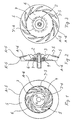
- FIG. 1 A in Fig. 1 with (1) designated pump impeller for a known per se and not shown in detail Centrifugal pump, especially for one in dishwashers or washing machines usable circulating pump according to the invention as the front and rear each semi-open impeller educated.
- Such an impeller (1) can in a provided with suction and discharge nozzle pump housing, as shown for example in DE 198 01 112 A1, are used.
- the Pump shaft seal in a conventional manner by means of a mechanical seal, consisting from a arranged in the motor-side shield of the pump housing rubber sleeve with fixed sliding ring made of sintered carbon material or the like.
- an abutment ring (2) made of ceramic material on the impeller (1).
- the sliding ring is supported by spring pressure on the perpendicular to the shaft sealing surface of the ceramic counter-bearing ring (2).
- the impeller (1) (Fig. 1 to 3) is provided with a plurality of blades (3), which differs from the Impeller hub (4) extend radially to the impeller outer circumference and between blade covers (5, 6) of the impeller (1) are arranged.
- the impeller (1) with the blade covers (5, 6) is inventively in one piece, preferably made in one piece, wherein the initially mentioned semi-open design is selected. After this construction cover both sides the rotor blades (3) provided blade covers (5, 6) the blades (3) front and back only partially off.
- the one-piece impeller (1) is designed as an injection molded part, wherein the ceramic counter-bearing ring (2) is preferably cast with.
- the ceramic counter-bearing ring (2) is preferably cast with.
- the ceramic counter-bearing ring (2) with a in the impeller material provided immersion gradation (7) and positively and / or non-positively in the impeller (1) fixed.
- the gradation (7) is encapsulated by the impeller material.
- the blades (3) end on the front blade cover (5) and concealed by this in the upper area on one Bucket outer circle diameter (A'-5).
- the blade outer circle diameter (A'-5) is preferable smaller than the outer diameter (A-5) of the annular front blade cover (5) elected.
- the outer diameter (A-6) of the rear blade cover (6) or the approximately equal inner diameter (I-5) of the front blade cover (5) lies approximately in the middle between the outer diameter (A-5) of the front blade cover (5) and the blade inner circle diameter (I'-6) the rear cover (6).
- the above-described shaping of the invention in an injection completely produced semi-open pump impeller (1) has the advantage that axial position tolerances of the impeller (1) can not affect the output power of the pump. Becomes assumed from the fact that the width of a leakage water gap between the open Buckets and the adjacent pump housing walls, not shown, the pump capacity influenced, so a negative influence does not occur because when moving of both sides semi-open impeller (1) on the one side enlarging Leakage water gap on the opposite side in the open blade area accordingly reduced. At the selected diameter ratios of the blade covers (5, 6) the effects (pressure distributions, etc.) cancel each other out, so that the pump performance at least constant. Experiments have shown that compared to the known, closed Impellers (DE 198 01 112 A1) even efficiency improvements occur.
- the impeller (1) promotes water / air mixtures or foam compared to known Klaufrädem with less disturbing noises, d. H. relatively quiet. This is achieved through the large bladed hub, because it sucked air bubbles on the inflow side Do not inject straight into the rear bucket cover and make noise on impact generate, but in the region of the impeller hub (4) deflected by the blades (3) and be crushed by the blades. This process takes place inside the impeller (1) instead of and is thus acoustically largely decoupled.
- Impellers are the volumes of shovel-free annular clearance between the impeller hub (4) and the initially mentioned pump housing or the front impeller cover (5) and the pump housing is reduced to less than half. By reducing the size of the annular space thus less air accumulates, so that bleeding the pump less is hampered.
- the impeller (1) can be made in one piece, because the outer diameter (A-6) of the rear wheel cover (6) equal to or slightly smaller than the inside diameter (I-5) of the front cover (5). If the counter ring bearing ceramic (2) is inserted into the impeller injection molding tool, this eliminates the separate mounting of the bearing. The complete impeller (1) can in one Operation are made. Likewise, the direct injection molded bearing ceramic reduces the number of components achieved, as a sealing sleeve and a separately used brass bushing can be omitted for receiving the ceramic disc. Direct injection of the ceramic counter bearing ring (2) is of course also applicable in a multi-part impeller.
Landscapes
- Engineering & Computer Science (AREA)
- Mechanical Engineering (AREA)
- General Engineering & Computer Science (AREA)
- Structures Of Non-Positive Displacement Pumps (AREA)
Claims (6)
- Pompe centrifuge, notamment pompe de circulation conçue pour être utilisée dans des lave-vaisselle ou des lave-linge, équipée d'une roue mobile (1) qui accomplit une révolution en contre-appui dans un carter de la pompe comportant des raccords d'aspiration et de pression, et est munie de plusieurs ailettes (3), ainsi que d'une bague de contre-appui (2) d'un système d'étanchement à bague de glissement, sachant que les ailettes (3) de la roue s'étendent radialement depuis le moyeu (4) jusqu'à la périphérie de ladite roue mobile (1) et sont disposées sur un capot antérieur (5), situé côté arrivée, et sur un capot postérieur (6) situé du côté du carter de la pompe,
caractérisée par le fait que les capots (5, 6) des ailettes confèrent, à la roue mobile (1), une réalisation semi-ouverte du fait que lesdits capots (5, 6) ne recouvrent que partiellement les ailettes (3) aux faces tant antérieure que postérieure, le capot antérieur (5) des ailettes étant réalisé en forme d'anneau circulaire, et le capot postérieur (6) desdites ailettes étant réalisé sous la forme d'un disque fermé muni d'un diamètre extérieur (A-6) égal ou inférieur au diamètre intérieur (I-5) dudit capot antérieur (5) desdites ailettes. - Pompe centrifuge à roue mobile selon la revendication 1,
caractérisée par le fait que ladite roue mobile (1) est fabriquée en tant que pièce venue de coulée, éventuellement d'un seul tenant avec une bague de contre-appui (2) en céramique intégrée par coulée. - Pompe centrifuge à roue mobile selon l'une des revendications 1 ou 2,
caractérisée par le fait que les ailettes (3) reliées au capot postérieur (6) débutent, devant le moyeu (4) de la roue mobile, sur un diamètre (I'-6) de circonférence intérieure desdites ailettes et s'achèvent, sur le capot antérieur (5), sur un diamètre (A'-5) de circonférence extérieure desdites ailettes qui est choisi, de préférence, inférieur au diamètre extérieur (A-5) du capot antérieur (5) en forme d'anneau circulaire. - Pompe centrifuge à roue mobile selon l'une ou plusieurs des revendications 1 à 3,
caractérisée par le fait que le diamètre extérieur (A-6) du capot postérieur (6) des ailettes ou, respectivement, le diamètre intérieur (1-5) du capot antérieur (5) desdites ailettes, approximativement identique, se trouve de préférence au centre entre le diamètre extérieur (A-5) du capot (5) situé côté arrivée, et le diamètre (I'-6) de la circonférence intérieure desdites ailettes. - Pompe centrifuge à roue mobile selon l'une ou plusieurs des revendications 1 à 4,
caractérisée par le fait que la bague de contre-appui (2) en céramique est verrouillée à demeure par concordance de formes et/ou mécaniquement dans la roue mobile (1). - Pompe centrifuge à roue mobile selon l'une ou plusieurs des revendications 1 à 5,
caractérisée par le fait que la bague de contre-appui (2) en céramique est pourvue d'un gradin (7) noyé dans le matériau constituant ladite roue mobile.
Applications Claiming Priority (2)
| Application Number | Priority Date | Filing Date | Title |
|---|---|---|---|
| DE10006983A DE10006983A1 (de) | 2000-02-16 | 2000-02-16 | Pumpenlaufrad für eine Kreiselpumpe, insbesondere für eine in Geschirrspülmaschinen oder Waschmaschinen einsetzbare Umwälzpumpe |
| DE10006983 | 2000-02-16 |
Publications (3)
| Publication Number | Publication Date |
|---|---|
| EP1126180A2 EP1126180A2 (fr) | 2001-08-22 |
| EP1126180A3 EP1126180A3 (fr) | 2002-08-14 |
| EP1126180B1 true EP1126180B1 (fr) | 2005-03-02 |
Family
ID=7631148
Family Applications (1)
| Application Number | Title | Priority Date | Filing Date |
|---|---|---|---|
| EP00126832A Expired - Lifetime EP1126180B1 (fr) | 2000-02-16 | 2000-12-07 | Roue d'une pompe centrifuge pour lave-vaisselle |
Country Status (4)
| Country | Link |
|---|---|
| EP (1) | EP1126180B1 (fr) |
| AT (1) | ATE290169T1 (fr) |
| DE (2) | DE10006983A1 (fr) |
| ES (1) | ES2234504T3 (fr) |
Cited By (2)
| Publication number | Priority date | Publication date | Assignee | Title |
|---|---|---|---|---|
| US10349810B2 (en) | 2017-08-08 | 2019-07-16 | Haier Us Appliance Solutions, Inc. | Pump assembly for a dishwashing appliance |
| US10349809B2 (en) | 2017-08-08 | 2019-07-16 | Haier Us Appliance Solutions, Inc. | Pump assembly for a dishwashing appliance |
Families Citing this family (12)
| Publication number | Priority date | Publication date | Assignee | Title |
|---|---|---|---|---|
| US7047914B2 (en) | 2001-02-15 | 2006-05-23 | Litens Automotive | Internal combustion engine combination with direct camshaft driven coolant pump |
| WO2004015274A2 (fr) * | 2002-08-13 | 2004-02-19 | Litens Automotive | Combinaison de moteur a combustion interne avec une pompe de refroidissement a entrainement direct par arbre a came |
| DE102005031589A1 (de) * | 2005-07-06 | 2007-01-11 | Schaeffler Kg | Wasserpumpenflügelrad |
| WO2011148397A1 (fr) * | 2010-05-28 | 2011-12-01 | Coplast Srl | Ventilateur de refroidissement pour machine tournante |
| WO2011148396A1 (fr) * | 2010-05-28 | 2011-12-01 | Coplast Srl | Ventilateur de refroidissement pour machine tournante |
| WO2011148398A1 (fr) * | 2010-05-28 | 2011-12-01 | Coplast Srl | Ventilateur de refroidissement pour machine tournante |
| CN102562650A (zh) * | 2010-12-08 | 2012-07-11 | 湖北省天门泵业有限公司 | 泵类半闭式叶轮 |
| ITPD20100386A1 (it) * | 2010-12-21 | 2012-06-22 | Unox Spa | Ventola perfezionata di ventilatore centrifugo, in particolare destinata a forni di cottura del tipo a convezione e metodo di fabbricazione di detta ventola |
| CN104141632B (zh) * | 2014-07-25 | 2016-04-06 | 吉首长潭泵业有限公司 | 耐磨合金砂浆泵叶轮及其制造方法 |
| CN105275834B (zh) * | 2015-10-27 | 2018-05-11 | 上海华鼓鼓风机有限公司 | 一种低速多级垂直剖分筒型结构的三元流离心鼓风机 |
| WO2022054403A1 (fr) * | 2020-09-14 | 2022-03-17 | 株式会社イワキ | Impulseur et pompe le comprenant |
| CN116221149A (zh) * | 2023-03-20 | 2023-06-06 | 青岛科技大学 | 一种抑制入口处工质冷凝和扩大稳定运行范围的离心压缩机结构 |
Family Cites Families (7)
| Publication number | Priority date | Publication date | Assignee | Title |
|---|---|---|---|---|
| US3079866A (en) * | 1959-07-16 | 1963-03-05 | Texaco Inc | Modified centrifugal pump |
| US3354529A (en) * | 1963-07-29 | 1967-11-28 | Ford Motor Co | Impeller making |
| DE3611910A1 (de) * | 1986-04-09 | 1987-10-15 | Schaeffler Waelzlager Kg | Laufrad fuer eine radialpumpe |
| DE3706770A1 (de) * | 1987-03-03 | 1988-09-15 | Licentia Gmbh | Kreiselpumpe, insbesondere fuer geschirrspuelmaschinen |
| DE3821352C1 (fr) * | 1988-06-24 | 1989-11-02 | Goetze Ag, 5093 Burscheid, De | |
| DE19530195A1 (de) * | 1995-08-17 | 1997-02-20 | Tuchenhagen Otto Gmbh | Kreiselpumpenlaufrad radialer Bauart |
| EP0854307B1 (fr) * | 1997-01-17 | 2003-04-16 | Miele & Cie. GmbH & Co. | Agencement pour réaliser l'étanchéité entre le rotor et le corps d'une pompe comprenant une garniture mécanique d'étanchéité |
-
2000
- 2000-02-16 DE DE10006983A patent/DE10006983A1/de not_active Withdrawn
- 2000-12-07 EP EP00126832A patent/EP1126180B1/fr not_active Expired - Lifetime
- 2000-12-07 DE DE50009642T patent/DE50009642D1/de not_active Expired - Lifetime
- 2000-12-07 AT AT00126832T patent/ATE290169T1/de not_active IP Right Cessation
- 2000-12-07 ES ES00126832T patent/ES2234504T3/es not_active Expired - Lifetime
Cited By (2)
| Publication number | Priority date | Publication date | Assignee | Title |
|---|---|---|---|---|
| US10349810B2 (en) | 2017-08-08 | 2019-07-16 | Haier Us Appliance Solutions, Inc. | Pump assembly for a dishwashing appliance |
| US10349809B2 (en) | 2017-08-08 | 2019-07-16 | Haier Us Appliance Solutions, Inc. | Pump assembly for a dishwashing appliance |
Also Published As
| Publication number | Publication date |
|---|---|
| DE10006983A1 (de) | 2001-08-23 |
| DE50009642D1 (de) | 2005-04-07 |
| EP1126180A3 (fr) | 2002-08-14 |
| ES2234504T3 (es) | 2005-07-01 |
| ATE290169T1 (de) | 2005-03-15 |
| EP1126180A2 (fr) | 2001-08-22 |
Similar Documents
| Publication | Publication Date | Title |
|---|---|---|
| EP1126180B1 (fr) | Roue d'une pompe centrifuge pour lave-vaisselle | |
| EP2211444B1 (fr) | Moteur électrique avec un effet de ventilateur de refroidissement | |
| EP1416123B1 (fr) | Générateur de tourbillons dans section d'admission | |
| EP1530670B1 (fr) | Structure de recirculation d'un turbocompresseur | |
| EP1767786B1 (fr) | Unité de pompe submersible | |
| JP5046449B2 (ja) | 血液ポンプ | |
| EP0786597B1 (fr) | Soufflante radial | |
| DE102013111889A1 (de) | Lüfterrad für Radiallüfter und Radiallüfter | |
| CN114857051B (zh) | 一种新型通风换气设备及风机 | |
| EP3833875B1 (fr) | Ventilateur radial | |
| EP2382393A1 (fr) | Soufflante de canal latéral, en particulier soufflante d'air secondaire pour une machine à combustion interne | |
| DE949899C (de) | Axialgeblaese oder -pumpe mit Schwenkbaren Laufschaufeln | |
| US2401206A (en) | Centrifugal compressor | |
| CN113250978A (zh) | 散热风扇 | |
| EP2971792B1 (fr) | Boîtier pour soufflante radiale de hotte aspirante | |
| EP1768233A1 (fr) | Tube d'entrefer | |
| EP2232080A1 (fr) | Rotor de pompe | |
| EP2546525A1 (fr) | Pompe centrifuge dotée d'un boîtier à spirales | |
| EP1767787B2 (fr) | Unité de pompe submersible | |
| WO2012123080A1 (fr) | Roue de ventilateur | |
| EP1081385A1 (fr) | Pompe d'alimentation | |
| WO2022128011A1 (fr) | Ventilateur et carter en volute pour ventilateur | |
| EP1327781B1 (fr) | Pompe centrifuge auto-amorçante | |
| DE202011003839U1 (de) | Lüfterrad | |
| DE112020007267T5 (de) | Verdichtergehäuse und Zentrifugalverdichter |
Legal Events
| Date | Code | Title | Description |
|---|---|---|---|
| PUAI | Public reference made under article 153(3) epc to a published international application that has entered the european phase |
Free format text: ORIGINAL CODE: 0009012 |
|
| AK | Designated contracting states |
Kind code of ref document: A2 Designated state(s): AT BE CH CY DE DK ES FI FR GB GR IE IT LI LU MC NL PT SE TR |
|
| AX | Request for extension of the european patent |
Free format text: AL;LT;LV;MK;RO;SI |
|
| PUAL | Search report despatched |
Free format text: ORIGINAL CODE: 0009013 |
|
| AK | Designated contracting states |
Kind code of ref document: A3 Designated state(s): AT BE CH CY DE DK ES FI FR GB GR IE IT LI LU MC NL PT SE TR |
|
| AX | Request for extension of the european patent |
Free format text: AL;LT;LV;MK;RO;SI |
|
| RIC1 | Information provided on ipc code assigned before grant |
Free format text: 7F 04D 29/22 A, 7F 04D 29/10 B, 7A 47L 15/42 B, 7D 06F 39/08 B |
|
| 17P | Request for examination filed |
Effective date: 20021106 |
|
| AKX | Designation fees paid |
Designated state(s): AT BE CH CY DE DK ES FI FR GB GR IE IT LI LU MC NL PT SE TR |
|
| RAP1 | Party data changed (applicant data changed or rights of an application transferred) |
Owner name: MIELE & CIE. KG |
|
| 17Q | First examination report despatched |
Effective date: 20040415 |
|
| GRAP | Despatch of communication of intention to grant a patent |
Free format text: ORIGINAL CODE: EPIDOSNIGR1 |
|
| GRAS | Grant fee paid |
Free format text: ORIGINAL CODE: EPIDOSNIGR3 |
|
| GRAA | (expected) grant |
Free format text: ORIGINAL CODE: 0009210 |
|
| AK | Designated contracting states |
Kind code of ref document: B1 Designated state(s): AT BE CH CY DE DK ES FI FR GB GR IE IT LI LU MC NL PT SE TR |
|
| PG25 | Lapsed in a contracting state [announced via postgrant information from national office to epo] |
Ref country code: FI Free format text: LAPSE BECAUSE OF FAILURE TO SUBMIT A TRANSLATION OF THE DESCRIPTION OR TO PAY THE FEE WITHIN THE PRESCRIBED TIME-LIMIT Effective date: 20050302 Ref country code: NL Free format text: LAPSE BECAUSE OF FAILURE TO SUBMIT A TRANSLATION OF THE DESCRIPTION OR TO PAY THE FEE WITHIN THE PRESCRIBED TIME-LIMIT Effective date: 20050302 Ref country code: IE Free format text: LAPSE BECAUSE OF FAILURE TO SUBMIT A TRANSLATION OF THE DESCRIPTION OR TO PAY THE FEE WITHIN THE PRESCRIBED TIME-LIMIT Effective date: 20050302 Ref country code: TR Free format text: LAPSE BECAUSE OF FAILURE TO SUBMIT A TRANSLATION OF THE DESCRIPTION OR TO PAY THE FEE WITHIN THE PRESCRIBED TIME-LIMIT Effective date: 20050302 |
|
| REG | Reference to a national code |
Ref country code: GB Ref legal event code: FG4D Free format text: NOT ENGLISH |
|
| REG | Reference to a national code |
Ref country code: CH Ref legal event code: EP |
|
| REG | Reference to a national code |
Ref country code: IE Ref legal event code: FG4D Free format text: GERMAN |
|
| REF | Corresponds to: |
Ref document number: 50009642 Country of ref document: DE Date of ref document: 20050407 Kind code of ref document: P |
|
| PG25 | Lapsed in a contracting state [announced via postgrant information from national office to epo] |
Ref country code: GR Free format text: LAPSE BECAUSE OF FAILURE TO SUBMIT A TRANSLATION OF THE DESCRIPTION OR TO PAY THE FEE WITHIN THE PRESCRIBED TIME-LIMIT Effective date: 20050602 Ref country code: DK Free format text: LAPSE BECAUSE OF FAILURE TO SUBMIT A TRANSLATION OF THE DESCRIPTION OR TO PAY THE FEE WITHIN THE PRESCRIBED TIME-LIMIT Effective date: 20050602 |
|
| REG | Reference to a national code |
Ref country code: ES Ref legal event code: FG2A Ref document number: 2234504 Country of ref document: ES Kind code of ref document: T3 |
|
| GBT | Gb: translation of ep patent filed (gb section 77(6)(a)/1977) |
Effective date: 20050616 |
|
| PG25 | Lapsed in a contracting state [announced via postgrant information from national office to epo] |
Ref country code: PT Free format text: LAPSE BECAUSE OF FAILURE TO SUBMIT A TRANSLATION OF THE DESCRIPTION OR TO PAY THE FEE WITHIN THE PRESCRIBED TIME-LIMIT Effective date: 20050803 |
|
| NLV1 | Nl: lapsed or annulled due to failure to fulfill the requirements of art. 29p and 29m of the patents act | ||
| REG | Reference to a national code |
Ref country code: IE Ref legal event code: FD4D |
|
| PG25 | Lapsed in a contracting state [announced via postgrant information from national office to epo] |
Ref country code: CY Free format text: LAPSE BECAUSE OF FAILURE TO SUBMIT A TRANSLATION OF THE DESCRIPTION OR TO PAY THE FEE WITHIN THE PRESCRIBED TIME-LIMIT Effective date: 20051207 Ref country code: AT Free format text: LAPSE BECAUSE OF NON-PAYMENT OF DUE FEES Effective date: 20051207 |
|
| PG25 | Lapsed in a contracting state [announced via postgrant information from national office to epo] |
Ref country code: LU Free format text: LAPSE BECAUSE OF NON-PAYMENT OF DUE FEES Effective date: 20051231 Ref country code: BE Free format text: LAPSE BECAUSE OF NON-PAYMENT OF DUE FEES Effective date: 20051231 Ref country code: MC Free format text: LAPSE BECAUSE OF NON-PAYMENT OF DUE FEES Effective date: 20051231 Ref country code: LI Free format text: LAPSE BECAUSE OF NON-PAYMENT OF DUE FEES Effective date: 20051231 Ref country code: CH Free format text: LAPSE BECAUSE OF NON-PAYMENT OF DUE FEES Effective date: 20051231 |
|
| PLBE | No opposition filed within time limit |
Free format text: ORIGINAL CODE: 0009261 |
|
| STAA | Information on the status of an ep patent application or granted ep patent |
Free format text: STATUS: NO OPPOSITION FILED WITHIN TIME LIMIT |
|
| 26N | No opposition filed |
Effective date: 20051205 |
|
| ET | Fr: translation filed | ||
| REG | Reference to a national code |
Ref country code: CH Ref legal event code: PL |
|
| REG | Reference to a national code |
Ref country code: GB Ref legal event code: 746 Effective date: 20061019 |
|
| BERE | Be: lapsed |
Owner name: MIELE & CIE. K.G. Effective date: 20051231 |
|
| PG25 | Lapsed in a contracting state [announced via postgrant information from national office to epo] |
Ref country code: SE Free format text: LAPSE BECAUSE OF FAILURE TO SUBMIT A TRANSLATION OF THE DESCRIPTION OR TO PAY THE FEE WITHIN THE PRESCRIBED TIME-LIMIT Effective date: 20050602 |
|
| PGFP | Annual fee paid to national office [announced via postgrant information from national office to epo] |
Ref country code: IT Payment date: 20121220 Year of fee payment: 13 Ref country code: GB Payment date: 20121218 Year of fee payment: 13 Ref country code: ES Payment date: 20121217 Year of fee payment: 13 |
|
| PGFP | Annual fee paid to national office [announced via postgrant information from national office to epo] |
Ref country code: FR Payment date: 20130123 Year of fee payment: 13 |
|
| GBPC | Gb: european patent ceased through non-payment of renewal fee |
Effective date: 20131207 |
|
| REG | Reference to a national code |
Ref country code: FR Ref legal event code: ST Effective date: 20140829 |
|
| PG25 | Lapsed in a contracting state [announced via postgrant information from national office to epo] |
Ref country code: GB Free format text: LAPSE BECAUSE OF NON-PAYMENT OF DUE FEES Effective date: 20131207 Ref country code: FR Free format text: LAPSE BECAUSE OF NON-PAYMENT OF DUE FEES Effective date: 20131231 |
|
| PGFP | Annual fee paid to national office [announced via postgrant information from national office to epo] |
Ref country code: DE Payment date: 20141231 Year of fee payment: 15 |
|
| REG | Reference to a national code |
Ref country code: ES Ref legal event code: FD2A Effective date: 20150429 |
|
| PG25 | Lapsed in a contracting state [announced via postgrant information from national office to epo] |
Ref country code: ES Free format text: LAPSE BECAUSE OF NON-PAYMENT OF DUE FEES Effective date: 20131208 |
|
| PG25 | Lapsed in a contracting state [announced via postgrant information from national office to epo] |
Ref country code: IT Free format text: LAPSE BECAUSE OF NON-PAYMENT OF DUE FEES Effective date: 20131231 |
|
| PG25 | Lapsed in a contracting state [announced via postgrant information from national office to epo] |
Ref country code: IT Free format text: LAPSE BECAUSE OF NON-PAYMENT OF DUE FEES Effective date: 20131207 |
|
| REG | Reference to a national code |
Ref country code: DE Ref legal event code: R119 Ref document number: 50009642 Country of ref document: DE |
|
| PG25 | Lapsed in a contracting state [announced via postgrant information from national office to epo] |
Ref country code: DE Free format text: LAPSE BECAUSE OF NON-PAYMENT OF DUE FEES Effective date: 20160701 |