EP1126231B1 - Dispositif pour ajuster l'angle de la crosse d'un fusil de chasse - Google Patents
Dispositif pour ajuster l'angle de la crosse d'un fusil de chasse Download PDFInfo
- Publication number
- EP1126231B1 EP1126231B1 EP00830811A EP00830811A EP1126231B1 EP 1126231 B1 EP1126231 B1 EP 1126231B1 EP 00830811 A EP00830811 A EP 00830811A EP 00830811 A EP00830811 A EP 00830811A EP 1126231 B1 EP1126231 B1 EP 1126231B1
- Authority
- EP
- European Patent Office
- Prior art keywords
- stock
- mobile
- plate
- vertical guide
- guide element
- Prior art date
- Legal status (The legal status is an assumption and is not a legal conclusion. Google has not performed a legal analysis and makes no representation as to the accuracy of the status listed.)
- Expired - Lifetime
Links
- 230000000717 retained effect Effects 0.000 claims description 4
- 230000008878 coupling Effects 0.000 claims description 2
- 238000010168 coupling process Methods 0.000 claims description 2
- 238000005859 coupling reaction Methods 0.000 claims description 2
- 230000000903 blocking effect Effects 0.000 description 2
- 230000006978 adaptation Effects 0.000 description 1
- 229920000642 polymer Polymers 0.000 description 1
- 230000001105 regulatory effect Effects 0.000 description 1
- 230000000007 visual effect Effects 0.000 description 1
Images

Classifications
-
- F—MECHANICAL ENGINEERING; LIGHTING; HEATING; WEAPONS; BLASTING
- F41—WEAPONS
- F41C—SMALLARMS, e.g. PISTOLS, RIFLES; ACCESSORIES THEREFOR
- F41C23/00—Butts; Butt plates; Stocks
- F41C23/14—Adjustable stock or stock parts, i.e. adaptable to personal requirements, e.g. length, pitch, cast or drop
Definitions
- This invention generally concerns the stocks of hunting and target practice shotguns and refers in more detail to a device for setting the angle of these stocks.
- rifle stocks can be created in special, customised shapes they sometimes have a longitudinal top part called a plate, cheek pad or even toe which can be moved and positioned with respect to the remaining part of the stock. This is to be able to vary the so-called angle of the stock, by setting it according to need, so that the person using the rifle can find a correct and reliable position for his support cheek.
- Various devices for this variation/adjustment of the stock angle have already been proposed. Examples among others are those described in US patents 2 432 519, 3 710 496, 5 580 219, 5 031 348, 5 235 764.
- EP-A-0 950 869 concerns, in accordance with the preamble features of claim 1, a device for regulating the position of a cheek-rest for gunstocks in which the cheek-rest and stock body are connected by props with a prustratic shape anchored immovably to a first plate and blocked in guide slots of a second place by means of dowel screws.
- the dowel screws can be tightened directly against the side of the props or through an interposed plate.
- the purpose of this invention is to propose and create a device for setting the angle in a rifle stock, a new device of original execution and one capable of permitting the moving and positioning of the mobile part of the stock in several directions for maximum effective adaptation of the configuration of the stock to the most widely diverse requirements of the person using the rifle.
- An advantage of the invention is that its components can be obtained from a pressed techno-polymer, thus reducing the engineering work and consequently the costs.
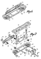
- the device essentially includes a fixed plate 11, a mobile plate 12, a vertical guide 13, a locking plate 14, a memory element 15 and two bushings 16.
- the stock for shotguns to which the device is applied usually includes a main body 17 and a mobile, attached part 18, called a plate or cheek pad which serves to set the angle of the stock.
- the mobile part 18 is located longitudinally in the upper part of the stock with the possibility of movements and orientation in various directions.
- the fixed plate 11 has holes 19 for the passage of the screws - not shown - to fix it longitudinally to the upper part of the main body 17 of the stock.
- the mobile plate 12 is fixed to the base of the mobile element 18 of the stock using screws - not shown - passing through holes 20 made in the plate itself.
- the mobile plate 12 is located facing the fixed plate 11 corresponding to a hollow 18, formed in the mobile element 18 of the stock.
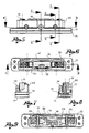
- the mobile plate 12 has a substantially rectangular opening 21 along its length. Along at least one of the longer sides of this opening 21 a square rib is created that rises up from the face of the mobile plate 12 opposed to the facing one of the fixed plate and therefore towards the bottom of hollow 18.
- the following are transversely made in the square rib 22: a central hole 23 and two similar holes 21, - these latter ones on opposite sides to the central one.
- two slots 25, spaced in parallel are made in the fixed plate 11.
- a rectangular recess 26 is made corresponding to each slot 25.
- Adjacent to each slot 25, a groove 27 may be made in the fixed plate 11 into which a sliding reference cap 28 may be inserted.
- the vertical guide element 13 is fixed to the plate 11 and passes freely into the opening 21 of the mobile plate 12, alongside the square rib 22 of this latter.
- the vertical guide 13 has a pair of vertical holes 29 into which a vertical blocking screw 30 is inserted from above.
- the screw 30 passes through a corresponding slot 25 in the fixed plate 11 and screws into a square nut 31 which is retained without rotating but which can translate in the rectangular recess 26 bellow the fixed plate corresponding to the slot itself.
- a bushing 16 may be inserted into each vertical hole 29, above the head of the blocking screw 30.
- the vertical guide 13 also has two U shaped recesses 32, spaced apart from each other, open at the top and extending downwards according to the height of the guide itself.
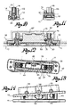
- the mobile plate 12 is fixed to the vertical guide 13 with the aid of the locking shoe 14, this latter, being arranged to the side of the vertical guide 13 on the side opposite to the square rib 22.
- the vertical guide 13 is positioned between the square rib 22 of the mobile plate 12 and the locking shoe 14.
- This fixing is obtained through transverse screws 33 which are inserted into the corresponding holes 24 of the said square rib 22, which pass through the recesses 32 of the said vertical guide 13 and into coinciding holes 34 made in the tightening shoe 14 and which screw into square nuts 35 on the external face of the said shoe; the nuts 35 being retained to stop them rotating in recesses 36 made on the external face of the shoe 14.
- a helical spring 37 is fitted around each transverse screw 33 which works between the square rib 22 and the tightening shoe 14, facilitating the release of the coupled parts when the said screws 33 are unscrewed.
- the screws 33 are accessible through holes made in the mobile part of the stock.
- the vertical guide 13 has an intermediate, tapered part 13' and the memory element 15 is located between the square rib 22 of the mobile plate 12 and the vertical guide 13, in correspondence with the said tapered part 13'. More precisely, the memory element 15 is fixed to the rib 22 with a screw 38 that is housed in the central hole made in the rib itself that passes through a coinciding slot 39 made in the memory element and which screws into a square nut 40, retained to prevent rotation but to permit translation in a groove 41 made in the element itself. This element oscillates on the shank of the screw 38 contrasted in this movement by the opposing springs 42.
- the mobile element of the stock can be then fixed in the desired position using the locking system, created as described above, with the assistance of the tightening shoe 14.
- the memory element 15 permits the setting and memorisation of every determinate position that must be reset after any movements of the mobile element of the stock.
- the guide element 13 may bear the graduations formed by knurlings 43 on at least one side to give a visual indication of the positions assumed by the mobile plate 12 and with this of the mobile element, above the main body of the stock, and for a better fixing and coupling between the rib 22 of the mobile plate 12 and the guide element 13.
Landscapes
- Engineering & Computer Science (AREA)
- General Engineering & Computer Science (AREA)
- Toys (AREA)
- Aiming, Guidance, Guns With A Light Source, Armor, Camouflage, And Targets (AREA)
- Walking Sticks, Umbrellas, And Fans (AREA)
- Paper (AREA)
- Pinball Game Machines (AREA)
- Addition Polymer Or Copolymer, Post-Treatments, Or Chemical Modifications (AREA)
- Magnetic Resonance Imaging Apparatus (AREA)
- Apparatus For Radiation Diagnosis (AREA)
- Eye Examination Apparatus (AREA)
- Investigating Or Analysing Materials By Optical Means (AREA)
- Warehouses Or Storage Devices (AREA)
Claims (7)
- Dispositif pour ajuster l'angle de la crosse d'un fusil de chasse, dans lequel la crosse se compose d'un corps principal (17) et d'un élément qui peut être déplacé (18), situé longitudinalement au-dessus d'une partie supérieure du corps principal et dans lequel le dispositif comprend une plaque fixe (11) devant être fixée à la partie supérieure du corps principal, une plaque mobile (12) devant être fixée à une base de l'élément mobile de la crosse faisant face à la plaque fixe, et un élément de guidage vertical (13) ancré perpendiculairement au-dessus de la plaque fixe (11) qui peut être positionné au moins dans une direction transversale par rapport à ladite plaque fixe, ledit élément de guidage vertical (13) passant librement dans une ouverture (21) aménagée dans la plaque mobile (12), caractérisé en ce que l'élément de guidage vertical (13) comprend deux évidements transversaux en forme de U (32) s'étendant conformément à la hauteur de l'élément de guidage (13) et s'ouvre vers le sommet, et en ce qu'il y a également des éléments (22, 14) pour bloquer ladite plaque mobile audit guide vertical (13) avec des vis de blocage transversales (33) qui bougent dans lesdits évidements transversaux en forme de U (32), accessibles à travers des trous correspondants aménagés dans l'élément mobile de la crosse, de manière à ce que ladite plaque mobile, avec l'élément mobile de la crosse fixé à celle-ci puisse être déplacée et positionnée dans plusieurs directions et de manière angulaire sur et par rapport au corps principal de la crosse.
- Dispositif selon la revendication 1 dans lequel un élément de mémoire (15), réglable en hauteur et oscillant suivant les mouvements de la plaque mobile, est placé entre la plaque mobile (12) et l'élément de guidage vertical (13).
- Dispositif selon les revendications 1 et 2 dans lequel ledit élément de guidage vertical (13) est ancré sur la plaque fixe (11) avec une paire de vis verticales (30) passant vers la base à partir du dessus qui bougent dans les fentes transversales (25) prévues dans ladite plaque fixe : chacune desdites vis se vissent dans leurs écrous non rotatifs respectifs (31) situés et retenus sous la plaque fixe.
- Dispositif selon les revendications 1 à 3 dans lequel, le long d'au moins un côté de l'ouverture (21) dans la plaque mobile (12), une nervure carrée (22) s'élève s'étendant de manière adjacente vers un côté de l'élément de guidage vertical (13), dans lequel le long d'un côté de ladite ouverture (21) s'étend un patin de blocage mobile (14) qui peut être séparé de la plaque mobile et dans lequel lesdites vis de blocage transversales (33) connectent ladite nervure carrée (22) audit patin de blocage (14) en passant à travers lesdits évidements en forme de U (32) pour bloquer la plaque mobile (12) sur l'élément de guidage vertical (13) dans chacune des positions prises par la plaque mobile avec l'élément de la crosse qui peut être déplacé.
- Dispositif selon la revendication 4 dans lequel au moins un ressort (37) est placé entre ladite nervure carrée (22) et ledit patin de blocage (14) pour relâcher ledit patin lorsque les vis transversales (33) sont dévissées.
- Dispositif selon les revendications précédentes dans lequel des gradations moletées (28, 43) sont marquées sur des parties de la plaque fixe et/ou de l'élément de guidage vertical pour afficher les différentes positions que la plaque mobile peut prendre par rapport à la fixe.
- Dispositif selon les revendications précédentes dans lequel les gradations moletées (28, 43) sont marquées sur des parties de la plaque fixe et/ou de l'élément de guidage vertical pour afficher les différentes positions que la plaque mobile peut prendre par rapport à la fixe, et pour une meilleure fixation et un meilleur couplage entre ladite plaque mobile (12) et l'élément de guidage.
Applications Claiming Priority (2)
| Application Number | Priority Date | Filing Date | Title |
|---|---|---|---|
| ITBS000010 | 2000-02-17 | ||
| IT2000BS000010A IT1314648B1 (it) | 2000-02-17 | 2000-02-17 | Disposiotivo di impostazione della piega in calci per fucili |
Publications (3)
| Publication Number | Publication Date |
|---|---|
| EP1126231A2 EP1126231A2 (fr) | 2001-08-22 |
| EP1126231A3 EP1126231A3 (fr) | 2002-04-10 |
| EP1126231B1 true EP1126231B1 (fr) | 2006-12-27 |
Family
ID=11440429
Family Applications (1)
| Application Number | Title | Priority Date | Filing Date |
|---|---|---|---|
| EP00830811A Expired - Lifetime EP1126231B1 (fr) | 2000-02-17 | 2000-12-11 | Dispositif pour ajuster l'angle de la crosse d'un fusil de chasse |
Country Status (8)
| Country | Link |
|---|---|
| US (1) | US6457273B2 (fr) |
| EP (1) | EP1126231B1 (fr) |
| JP (1) | JP2001227899A (fr) |
| AT (1) | ATE349668T1 (fr) |
| DE (1) | DE60032574D1 (fr) |
| ES (1) | ES2279754T3 (fr) |
| IT (1) | IT1314648B1 (fr) |
| TR (1) | TR200003782A2 (fr) |
Cited By (1)
| Publication number | Priority date | Publication date | Assignee | Title |
|---|---|---|---|---|
| WO2018108982A1 (fr) | 2016-12-13 | 2018-06-21 | Guillerm Gael | Crosse articulee pour arme a appui d'epaule |
Families Citing this family (16)
| Publication number | Priority date | Publication date | Assignee | Title |
|---|---|---|---|---|
| DE10338285B4 (de) * | 2003-08-20 | 2005-09-15 | STOPPER Schießsportausrüstungen GmbH & Co. KG | Schaftkappe |
| DE102005004978B4 (de) * | 2005-02-04 | 2006-11-30 | S.A.T. Swiss Arms Technology Ag | Verstellbare Schaftkappe für eine Handfeuerwaffe |
| US7726060B1 (en) | 2005-02-22 | 2010-06-01 | J. Allen Enterprises, Inc. | Firearm fastening assembly and method of use |
| US7805873B2 (en) * | 2005-11-08 | 2010-10-05 | Blackhawk Industries Product Group Unlimited Llc | Modular cheek rest and storage assembly |
| US20120036757A1 (en) * | 2010-08-12 | 2012-02-16 | Larue Mark C | Gun-stock riser for AR15 type tactical firearm |
| DE102010048906B4 (de) | 2010-10-08 | 2012-06-28 | Carsten Dreses | Ergonomische Schaftkappe |
| US9631885B2 (en) | 2011-01-13 | 2017-04-25 | J. Allen Enterprises, Inc. | Rifle stock assembly for different barreled receivers |
| IT1404173B1 (it) * | 2011-02-15 | 2013-11-15 | Bresciana Armi Fabarm | Calcio regolabile perfezionato per fucili |
| SE537395C2 (sv) * | 2013-09-06 | 2015-04-21 | Anslutningsanordning och förfarande för att ansluta kindstödtill en gevärsstock | |
| USD804602S1 (en) | 2016-01-12 | 2017-12-05 | Magpul Industries Corp. | Firearm stock |
| ES2582980B1 (es) * | 2016-03-07 | 2017-04-11 | José Manuel DÍAZ AJA | Culata regulable de apoyo en el hombro para armas de fuego |
| FR3062716B1 (fr) * | 2017-02-08 | 2019-04-05 | M.C.D | Dispositif de reglage pour une crosse de fusil |
| WO2021030860A1 (fr) * | 2019-08-19 | 2021-02-25 | Bespoke Engineering Pty Ltd | Crosse réglable |
| FR3110965A1 (fr) * | 2020-05-29 | 2021-12-03 | M.C.D | Busc pour crosse de fusil |
| US11841208B1 (en) | 2020-06-24 | 2023-12-12 | Mark John Roth | Universally adjustable firearm stock |
| USD1001950S1 (en) | 2020-09-08 | 2023-10-17 | Mark John Roth | Stock framework |
Family Cites Families (20)
| Publication number | Priority date | Publication date | Assignee | Title |
|---|---|---|---|---|
| DE137376C (fr) * | ||||
| CH101632A (de) * | 1923-09-14 | 1923-11-16 | Haemmerli Rudolf | Kolbenkappe an Gewehren, insbesondere Scheibenstutzen. |
| FR735860A (fr) * | 1932-04-23 | 1932-11-16 | Fusil de tranchée à visée indirecte et vice versa | |
| US2432519A (en) | 1945-05-24 | 1947-12-16 | John C Garand | Cheek rest for firearms |
| DE1789152U (de) * | 1958-12-12 | 1959-05-21 | Erich Wolf | Schaftkolben fuer gewehre aller art. |
| US3710496A (en) | 1970-09-08 | 1973-01-16 | Mershon Co | Firearm adjustable cheek piece |
| US4122623A (en) * | 1977-09-28 | 1978-10-31 | Stice Eldon C | Adjustable gun stock |
| DE3129182C2 (de) * | 1981-07-24 | 1985-05-09 | Carl Walther Gmbh, 7900 Ulm | Schaftbacke, insbesondere für Sportgewehre |
| US4589219A (en) * | 1984-08-31 | 1986-05-20 | The Coleman Company, Inc. | Adjustable cheekpiece for gunstock |
| US4663877A (en) * | 1985-11-25 | 1987-05-12 | Bragg Elmore J | Shoulder firearm recoil absorbing mechanism |
| US4896446A (en) * | 1989-07-10 | 1990-01-30 | G. Squared, Inc. | Buttplate and comb assembly for shoulder firearms |
| US5031348A (en) | 1990-10-01 | 1991-07-16 | Carey Donald C | Gun stock assembly with coordinated comb and recoil |
| IT1253058B (it) | 1991-11-19 | 1995-07-10 | Perazzi Armi Spa | Calcio per fucili con guanciale a posizione regolabile |
| US5392553A (en) * | 1994-01-11 | 1995-02-28 | Carey; Donald C. | Gun stock assembly with universally adjustable comb piece |
| CA2120073A1 (fr) * | 1994-03-28 | 1995-09-29 | Luigi Iannetta | Mecanisme anti-recul pour monture de fusil |
| US5580219A (en) | 1995-03-06 | 1996-12-03 | Solar Turbines Incorporated | Ceramic blade attachment system |
| CA2206237A1 (fr) * | 1997-05-27 | 1998-11-27 | Luigi Iannetta | Ensemble de busc pour une arme d'epaule |
| US5970642A (en) * | 1998-01-29 | 1999-10-26 | Martin; Billy B. | Ergonomic adjustable gun stock |
| IT1300569B1 (it) * | 1998-04-15 | 2000-05-23 | Rizzini Di Rizzini Battista & | Dispositivo per la regolazione in piu' direzioni della posizione delguanciale di un calcio per fucili |
| US5933997A (en) * | 1998-08-26 | 1999-08-10 | Browning | Adjustable comb apparatus |
-
2000
- 2000-02-17 IT IT2000BS000010A patent/IT1314648B1/it active
- 2000-12-11 EP EP00830811A patent/EP1126231B1/fr not_active Expired - Lifetime
- 2000-12-11 ES ES00830811T patent/ES2279754T3/es not_active Expired - Lifetime
- 2000-12-11 AT AT00830811T patent/ATE349668T1/de not_active IP Right Cessation
- 2000-12-11 DE DE60032574T patent/DE60032574D1/de not_active Expired - Lifetime
- 2000-12-18 US US09/739,522 patent/US6457273B2/en not_active Expired - Fee Related
- 2000-12-19 TR TR2000/03782A patent/TR200003782A2/xx unknown
-
2001
- 2001-01-05 JP JP2001000406A patent/JP2001227899A/ja active Pending
Cited By (1)
| Publication number | Priority date | Publication date | Assignee | Title |
|---|---|---|---|---|
| WO2018108982A1 (fr) | 2016-12-13 | 2018-06-21 | Guillerm Gael | Crosse articulee pour arme a appui d'epaule |
Also Published As
| Publication number | Publication date |
|---|---|
| ES2279754T3 (es) | 2007-09-01 |
| DE60032574D1 (de) | 2007-02-08 |
| EP1126231A2 (fr) | 2001-08-22 |
| ITBS20000010A1 (it) | 2001-08-17 |
| US20010037597A1 (en) | 2001-11-08 |
| US6457273B2 (en) | 2002-10-01 |
| ATE349668T1 (de) | 2007-01-15 |
| IT1314648B1 (it) | 2002-12-31 |
| ITBS20000010A0 (it) | 2000-02-17 |
| JP2001227899A (ja) | 2001-08-24 |
| TR200003782A3 (tr) | 2001-09-21 |
| TR200003782A2 (tr) | 2001-09-21 |
| EP1126231A3 (fr) | 2002-04-10 |
Similar Documents
| Publication | Publication Date | Title |
|---|---|---|
| EP1126231B1 (fr) | Dispositif pour ajuster l'angle de la crosse d'un fusil de chasse | |
| AU645780B2 (en) | Multifunctional rachis osteosynthesis device | |
| US7536819B2 (en) | Adjustable recoil pad for a small arm | |
| EP0750477B1 (fr) | Dispositif de fixation pour dispositif d'accouplement transversal rigide entre les broches d'un systeme d'osteosynthese spinale | |
| ES2761802T3 (es) | Dispositivo ortopédico para corregir deformidades de huesos largos | |
| US5129903A (en) | Bone plate | |
| US8157864B2 (en) | Vertebral replacement device | |
| US6306139B1 (en) | Intervertebral connection device with an anti-extraction device to prevent extraction of anchoring screws | |
| CA2056253C (fr) | Dispositif d'ancrage | |
| US4625613A (en) | Adjustable bridge and tuning unit for a stringed musical instrument | |
| US4559707A (en) | Error correction system for length measuring device | |
| KR19990066961A (ko) | 골판 | |
| US5454153A (en) | Adjustable assembly for use in the repair or replacement of a pitch change link or rod end of critical predetermined length | |
| US3977041A (en) | Hinge device | |
| US4367566A (en) | Mounting plate for a furniture hinge | |
| US4732228A (en) | Precision balance | |
| PL208672B1 (pl) | Urządzenie regulacyjne zawiasy do drzwi lub okien | |
| US4916265A (en) | Adjustable mounting assembly for a limit switch | |
| US5054147A (en) | Fabrication last for shoe manufacture on a computer-controlled transfer line | |
| US4422256A (en) | Adjustable cheek-piece for a shoulder firearm | |
| DK1006860T3 (da) | Pandebånd med justerbar anordning til placering af en optisk indretning | |
| EP0950869A3 (fr) | Dispositif pour ajuster la direction et la position d'un support de joue monté sur la crosse d'un fusil | |
| CN110916756A (zh) | 一种用于手术的角度可调股骨截骨组件 | |
| ES2221507B1 (es) | Dispositivo para posicionar y fijar en obra marcos para puertas. | |
| SU1096090A1 (ru) | Отвертка |
Legal Events
| Date | Code | Title | Description |
|---|---|---|---|
| PUAI | Public reference made under article 153(3) epc to a published international application that has entered the european phase |
Free format text: ORIGINAL CODE: 0009012 |
|
| AK | Designated contracting states |
Kind code of ref document: A2 Designated state(s): AT BE CH CY DE DK ES FI FR GB GR IE IT LI LU MC NL PT SE TR |
|
| AX | Request for extension of the european patent |
Free format text: AL;LT;LV;MK;RO;SI |
|
| PUAL | Search report despatched |
Free format text: ORIGINAL CODE: 0009013 |
|
| AK | Designated contracting states |
Kind code of ref document: A3 Designated state(s): AT BE CH CY DE DK ES FI FR GB GR IE IT LI LU MC NL PT SE TR |
|
| AX | Request for extension of the european patent |
Free format text: AL;LT;LV;MK;RO;SI |
|
| 17P | Request for examination filed |
Effective date: 20020722 |
|
| AKX | Designation fees paid |
Free format text: AT BE CH CY DE DK ES FI FR GB GR IE IT LI LU MC NL PT SE TR |
|
| GRAP | Despatch of communication of intention to grant a patent |
Free format text: ORIGINAL CODE: EPIDOSNIGR1 |
|
| GRAS | Grant fee paid |
Free format text: ORIGINAL CODE: EPIDOSNIGR3 |
|
| GRAA | (expected) grant |
Free format text: ORIGINAL CODE: 0009210 |
|
| RAP1 | Party data changed (applicant data changed or rights of an application transferred) |
Owner name: FABBRICA D'ARMI P.BERETTA S.P.A. |
|
| AK | Designated contracting states |
Kind code of ref document: B1 Designated state(s): AT BE CH CY DE DK ES FI FR GB GR IE IT LI LU MC NL PT SE TR |
|
| PG25 | Lapsed in a contracting state [announced via postgrant information from national office to epo] |
Ref country code: DK Free format text: LAPSE BECAUSE OF FAILURE TO SUBMIT A TRANSLATION OF THE DESCRIPTION OR TO PAY THE FEE WITHIN THE PRESCRIBED TIME-LIMIT Effective date: 20061227 Ref country code: CH Free format text: LAPSE BECAUSE OF FAILURE TO SUBMIT A TRANSLATION OF THE DESCRIPTION OR TO PAY THE FEE WITHIN THE PRESCRIBED TIME-LIMIT Effective date: 20061227 Ref country code: AT Free format text: LAPSE BECAUSE OF FAILURE TO SUBMIT A TRANSLATION OF THE DESCRIPTION OR TO PAY THE FEE WITHIN THE PRESCRIBED TIME-LIMIT Effective date: 20061227 Ref country code: FI Free format text: LAPSE BECAUSE OF FAILURE TO SUBMIT A TRANSLATION OF THE DESCRIPTION OR TO PAY THE FEE WITHIN THE PRESCRIBED TIME-LIMIT Effective date: 20061227 Ref country code: NL Free format text: LAPSE BECAUSE OF FAILURE TO SUBMIT A TRANSLATION OF THE DESCRIPTION OR TO PAY THE FEE WITHIN THE PRESCRIBED TIME-LIMIT Effective date: 20061227 Ref country code: LI Free format text: LAPSE BECAUSE OF FAILURE TO SUBMIT A TRANSLATION OF THE DESCRIPTION OR TO PAY THE FEE WITHIN THE PRESCRIBED TIME-LIMIT Effective date: 20061227 |
|
| REG | Reference to a national code |
Ref country code: GB Ref legal event code: FG4D |
|
| REG | Reference to a national code |
Ref country code: IE Ref legal event code: FG4D |
|
| REF | Corresponds to: |
Ref document number: 60032574 Country of ref document: DE Date of ref document: 20070208 Kind code of ref document: P |
|
| PG25 | Lapsed in a contracting state [announced via postgrant information from national office to epo] |
Ref country code: SE Free format text: LAPSE BECAUSE OF FAILURE TO SUBMIT A TRANSLATION OF THE DESCRIPTION OR TO PAY THE FEE WITHIN THE PRESCRIBED TIME-LIMIT Effective date: 20070327 |
|
| PG25 | Lapsed in a contracting state [announced via postgrant information from national office to epo] |
Ref country code: DE Free format text: LAPSE BECAUSE OF FAILURE TO SUBMIT A TRANSLATION OF THE DESCRIPTION OR TO PAY THE FEE WITHIN THE PRESCRIBED TIME-LIMIT Effective date: 20070328 |
|
| PG25 | Lapsed in a contracting state [announced via postgrant information from national office to epo] |
Ref country code: PT Free format text: LAPSE BECAUSE OF FAILURE TO SUBMIT A TRANSLATION OF THE DESCRIPTION OR TO PAY THE FEE WITHIN THE PRESCRIBED TIME-LIMIT Effective date: 20070528 |
|
| NLV1 | Nl: lapsed or annulled due to failure to fulfill the requirements of art. 29p and 29m of the patents act | ||
| REG | Reference to a national code |
Ref country code: CH Ref legal event code: PL |
|
| EN | Fr: translation not filed | ||
| REG | Reference to a national code |
Ref country code: ES Ref legal event code: FG2A Ref document number: 2279754 Country of ref document: ES Kind code of ref document: T3 |
|
| PLBE | No opposition filed within time limit |
Free format text: ORIGINAL CODE: 0009261 |
|
| STAA | Information on the status of an ep patent application or granted ep patent |
Free format text: STATUS: NO OPPOSITION FILED WITHIN TIME LIMIT |
|
| 26N | No opposition filed |
Effective date: 20070928 |
|
| PG25 | Lapsed in a contracting state [announced via postgrant information from national office to epo] |
Ref country code: GR Free format text: LAPSE BECAUSE OF FAILURE TO SUBMIT A TRANSLATION OF THE DESCRIPTION OR TO PAY THE FEE WITHIN THE PRESCRIBED TIME-LIMIT Effective date: 20070328 Ref country code: FR Free format text: LAPSE BECAUSE OF FAILURE TO SUBMIT A TRANSLATION OF THE DESCRIPTION OR TO PAY THE FEE WITHIN THE PRESCRIBED TIME-LIMIT Effective date: 20070817 |
|
| PG25 | Lapsed in a contracting state [announced via postgrant information from national office to epo] |
Ref country code: MC Free format text: LAPSE BECAUSE OF NON-PAYMENT OF DUE FEES Effective date: 20071231 |
|
| GBPC | Gb: european patent ceased through non-payment of renewal fee |
Effective date: 20071211 |
|
| PG25 | Lapsed in a contracting state [announced via postgrant information from national office to epo] |
Ref country code: IE Free format text: LAPSE BECAUSE OF NON-PAYMENT OF DUE FEES Effective date: 20071211 |
|
| PG25 | Lapsed in a contracting state [announced via postgrant information from national office to epo] |
Ref country code: FR Free format text: LAPSE BECAUSE OF FAILURE TO SUBMIT A TRANSLATION OF THE DESCRIPTION OR TO PAY THE FEE WITHIN THE PRESCRIBED TIME-LIMIT Effective date: 20061227 |
|
| PG25 | Lapsed in a contracting state [announced via postgrant information from national office to epo] |
Ref country code: GB Free format text: LAPSE BECAUSE OF NON-PAYMENT OF DUE FEES Effective date: 20071211 |
|
| PGFP | Annual fee paid to national office [announced via postgrant information from national office to epo] |
Ref country code: ES Payment date: 20081028 Year of fee payment: 9 |
|
| PGFP | Annual fee paid to national office [announced via postgrant information from national office to epo] |
Ref country code: BE Payment date: 20090126 Year of fee payment: 9 |
|
| PG25 | Lapsed in a contracting state [announced via postgrant information from national office to epo] |
Ref country code: CY Free format text: LAPSE BECAUSE OF FAILURE TO SUBMIT A TRANSLATION OF THE DESCRIPTION OR TO PAY THE FEE WITHIN THE PRESCRIBED TIME-LIMIT Effective date: 20061227 Ref country code: LU Free format text: LAPSE BECAUSE OF NON-PAYMENT OF DUE FEES Effective date: 20071211 |
|
| BERE | Be: lapsed |
Owner name: FABBRICA D'ARMI P.BERETTA S.P.A. Effective date: 20091231 |
|
| PG25 | Lapsed in a contracting state [announced via postgrant information from national office to epo] |
Ref country code: BE Free format text: LAPSE BECAUSE OF NON-PAYMENT OF DUE FEES Effective date: 20091231 |
|
| REG | Reference to a national code |
Ref country code: ES Ref legal event code: FD2A Effective date: 20110304 |
|
| PGFP | Annual fee paid to national office [announced via postgrant information from national office to epo] |
Ref country code: TR Payment date: 20101122 Year of fee payment: 11 Ref country code: IT Payment date: 20101218 Year of fee payment: 11 |
|
| PG25 | Lapsed in a contracting state [announced via postgrant information from national office to epo] |
Ref country code: ES Free format text: LAPSE BECAUSE OF NON-PAYMENT OF DUE FEES Effective date: 20110303 |
|
| PG25 | Lapsed in a contracting state [announced via postgrant information from national office to epo] |
Ref country code: ES Free format text: LAPSE BECAUSE OF NON-PAYMENT OF DUE FEES Effective date: 20091212 |
|
| PG25 | Lapsed in a contracting state [announced via postgrant information from national office to epo] |
Ref country code: IT Free format text: LAPSE BECAUSE OF NON-PAYMENT OF DUE FEES Effective date: 20111211 |
|
| PG25 | Lapsed in a contracting state [announced via postgrant information from national office to epo] |
Ref country code: TR Free format text: LAPSE BECAUSE OF NON-PAYMENT OF DUE FEES Effective date: 20111211 |