EP1126429A2 - Dispositif électronique pour détecter des gaz narcotiques - Google Patents
Dispositif électronique pour détecter des gaz narcotiques Download PDFInfo
- Publication number
- EP1126429A2 EP1126429A2 EP01103870A EP01103870A EP1126429A2 EP 1126429 A2 EP1126429 A2 EP 1126429A2 EP 01103870 A EP01103870 A EP 01103870A EP 01103870 A EP01103870 A EP 01103870A EP 1126429 A2 EP1126429 A2 EP 1126429A2
- Authority
- EP
- European Patent Office
- Prior art keywords
- deriver
- alarm
- sensor
- foregoing
- output
- Prior art date
- Legal status (The legal status is an assumption and is not a legal conclusion. Google has not performed a legal analysis and makes no representation as to the accuracy of the status listed.)
- Withdrawn
Links
Images

Classifications
-
- G—PHYSICS
- G08—SIGNALLING
- G08B—SIGNALLING SYSTEMS, e.g. PERSONAL CALLING SYSTEMS; ORDER TELEGRAPHS; ALARM SYSTEMS
- G08B21/00—Alarms responsive to a single specified undesired or abnormal condition and not otherwise provided for
- G08B21/02—Alarms for ensuring the safety of persons
- G08B21/12—Alarms for ensuring the safety of persons responsive to undesired emission of substances, e.g. pollution alarms
- G08B21/14—Toxic gas alarms
-
- G—PHYSICS
- G08—SIGNALLING
- G08B—SIGNALLING SYSTEMS, e.g. PERSONAL CALLING SYSTEMS; ORDER TELEGRAPHS; ALARM SYSTEMS
- G08B21/00—Alarms responsive to a single specified undesired or abnormal condition and not otherwise provided for
- G08B21/02—Alarms for ensuring the safety of persons
- G08B21/12—Alarms for ensuring the safety of persons responsive to undesired emission of substances, e.g. pollution alarms
Definitions
- the present invention relates to an electronic narcotic gas detecting device.
- an electronic narcotic gas detecting device as claimed in Claim 1.
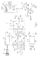
- Number 1 in Figure 1 indicates as a whole an electronic narcotic gas detecting device comprising:
- gas sensor 4 which is of known type, may comprise a tubular metal outer casing (not shown) housing a heating element 14 having first and second output terminals 14a, 14b, and a sensitive element 15 connected to heating element 14 and having first and second output terminals 15a, 15b.
- heating element 14 When powered, heating element 14 provides for heating sensitive element 15 to a predetermined operating temperature; and sensitive element 15 is also connected outside the casing, and has a resistance varying as a function of the presence and concentration of a number of substances to which element 15 is sensitive.
- the sensors used are not necessarily specially designed for detecting narcotic gas, and may comprise sensors normally used for detecting other compounds, such as:
- Tests have shown sensors for detecting alcohol vapors, chloro Fluoro carbides (CFC) and fuel gases to be particularly sensitive to narcotic agents.
- CFC chloro Fluoro carbides
- FIGARO ENGINEERING INC. OSAKA 562-8505 JAPAN, for example, may be used to advantage.
- Gas detecting circuit 3 comprises a first resistor 17 having a first terminal connected to voltage source Vdc , and a second terminal connected to the first terminal 15a of sensitive element 15, the second terminal 15b of which is connected to a reference potential (ground) 18.
- Resistor 17 and sensitive element 15 thus form a resistive divider for distributing supply voltage Vdc .
- Vout Vdc*(R 15 ) / (R 15 +R 17 ) where R 15 is the resistance value of sensitive element 15, and R 17 the resistance value of resistor 17. Voltage Vout varies according to the presence and concentration of narcotic gas, and represents the output signal of sensor 4.
- Heating element 14 has the first terminal 14a connected to supply voltage Vdc , and the second terminal 14b connected to reference potential 18, so that supply voltage Vdc is applied directly to heating element 14.
- Gas detecting circuit 3 comprises a deriver element 20, the input of which is supplied with output signal Vout . More specifically, in the example embodiment shown, deriver element 20 comprises a capacitor having a first terminal 20a connected to first terminal 15a, and a second terminal 20b connected to a first terminal of a second resistor 22, the second terminal of which is connected to reference potential 18.
- deriver element 20 may comprise a numeric deriver, in which case, output signal Vout would be a digital signal.
- a capacitor 24 is placed parallel to resistor 22 to form a resistive-capacitive RC band-pass filter 25 connected to the output of deriver element 20.
- Gas detecting circuit 3 also comprises an integrating element 27 having an input connected to the output of deriver element 20. More specifically, in the example embodiment shown, integrating element 27 comprises an operational amplifier 30 having an inverting input (-) connected to terminal 20b of capacitor 20, and a noninverting input (+) supplied with a reference voltage Vref . Integrating element 27 also comprises a third resistor 33 having a first terminal connected to the inverting input (-), and a second terminal connected to a first terminal of a capacitor 35, the second terminal of which is connected to the output 30u of operational amplifier 30. The output of operational amplifier 30 also defines the output of gas detecting circuit 3.
- Gas detecting circuit 3 also comprises a fourth resistor 37 having a first terminal connected to voltage source Vdc , and a second terminal connected to a first terminal of a trimmer 38, the second terminal of which is connected to reference potential 18.
- the movable terminal of trimmer 38 supplies the noninverting input (+) of operational amplifier 30 with voltage Vref ; and a fifth resistor 39 is interposed between reference potential 18 and output 30u of operational amplifier 30.
- Power supply circuit 12 is of known type and converts the alternating mains voltage (220 volts, 50Hz) at a pin 42 into regulated direct voltage Vdc , which may conveniently be +5 volts. Power supply circuit 12 may also be a static type and convert a direct voltage supplied by a battery (not shown) into regulated direct voltage Vdc.
- brightness detecting circuit 10 comprises a photosensitive element (e.g. photoresistor) 46, and supplies an output 10u with a voltage which assumes a first value (e.g. close to Vdc) when the brightness detected by photosensitive element 46 is below a given threshold value, and a second value (e.g. close to zero) when the brightness detected by photosensitive element 46 is above the threshold value.
- a photosensitive element e.g. photoresistor
- Output 10u of brightness detector 10 is connected via a resistor 48 to a first terminal of a bright light-emitting diode 50 having a second terminal connected to reference potential 18 via a (normally-closed) switch 52.
- Output 10u of brightness detector 10 is also connected via a resistor 54 to the base terminal of an NPN transistor 56, the emitter of which is connected to reference potential 18, and the collector of which communicates with a terminal supplying alarm and signaling circuit 7.
- Transistor 56 acts as a switch and, when closed, permits supply to alarm and signaling circuit 7.
- Alarm and signaling circuit 7 comprises an oscillator circuit 60 supplying an excitation signal for a transducer 62, in particular a piezoelectric transducer; and at least one internal switch (shown schematically by a transistor 64) which, when closed (with circuit 7 connected to power supply Vdc ), activates oscillator circuit 60 to emit an alarm signal by means of transducer 62.
- Gas detecting circuit 3 is connected at the output to switch 64 via a resistor 66, so that switch 64 is tripped by the output signal of gas detecting circuit 3.
- An auxiliary (normally-open) switch 70 is located between reference potential 18 and the collector of transistor 56.
- the user inserts plug 42 into a power socket 72 to supply gas detecting circuit 3, alarm and signaling circuit 7, and brightness detecting circuit 10.
- the output voltage to sensor 4 does not vary (or barely noticeably, due to drift of the sensor), the output of deriver element 20 is substantially zero, and the voltage applied to the inverting input (-) is barely positive, so that the voltage at output 30u is. insufficient to close transistor 64, and alarm and signal circuit 7 remains off.
- narcotic gas GAS
- the narcotic gas spreads rapidly through the air and reaches sensor 4 in only a few seconds; the resistance of sensitive element 15 of the sensor struck by the narcotic gas molecules changes instantly : in particular falls, so that output signal Vout varies rapidly with time; the variation in signal Vout is detected by deriver element 20, which generates a derived signal s(t) approximately proportional to the rate of change of the output signal of sensor 4, i.e.
- Switch 64 is thus closed and a sound alarm signal emitted to indicate the presence of narcotic gas.
- the user is thus alerted and may leave the room to take the appropriate steps before the gas takes effect.
- any voltage peaks in derived signal s(t) are eliminated by band-pass filter 25; and any oscillatory (e.g. sinusoidal) noise in derived signal s(t) is eliminated by equal portions of opposite sign of the signal canceling one another out in the integration operation.
- the alarm signal can only be emitted when a dark level is detected by circuit 10, in which condition, the output of circuit 10 is at a high voltage value and switch 56 is closed, thus permitting supply of circuit 7. Conversely, in bright conditions, the output of circuit 10 is at a low voltage value and switch 56 is open, thus cutting off supply to circuit 7.
- switch 70 When closed, switch 70 short-circuits transistor 56 to connect circuit 7 continuously to the supply voltage, regardless of the output value of circuit 10 and, hence, the brightness level detected.
- the device according to the present invention may conveniently be formed on a rectangular printed circuit 80 ( Figure 2) supporting all the electronic components 81 (shown schematically) of the device.
- Printed circuit 80 may be housed in a grippable, hollow, parallelepiped-shaped insulating casing 82, which also conveniently comprises a gas inlet (not shown), and an integral parallelepiped-shaped appendix 84 fitted on the end with two elongated metal elements 85 defining the terminals of plug 42.
- the device according to the present invention provides for fast, effective detection of narcotic gas.
- the device according to the present invention also provides for detecting a large number of narcotic agents, some of which are listed below by way of non-limiting examples:
- Deriver element 20 also provides for releasing operation of gas detecting circuit 3 from the output voltage level of sensor 4. Applying the deriver function, in fact, provides for generating, at the output of element 20, a derived signal which is purely a function of the variation in signal Vout , and does not depend on the output voltage value of the sensor. The derived signal s(t) is then integrated and contributes towards activating alarm signal 7, so that the device according to the present invention operates differentially.
- the output voltage value of the sensors used is practically impossible to determine, by depending on a number of external factors (operating temperature, humidity, etc.), and may vary gradually over the first few days/weeks' operation of the sensor.
- problems could arise if the output voltage of the sensor were to be compared directly with a reference value, owing to the reference value possibly being difficult to identify, and the output voltage drift of the sensor possibly resulting in malfunctioning of the device.
- the output voltage drift of the sensor produces no variation in the output voltage of the deriver element, by being extremely slow, and by d(Vout)/d(t) anyway remaining substantially equal to zero.
- sensors other than the one described above which supplies a variation in resistance, and hence voltage, in the presence of a narcotic agent, may be used, e.g. sensors supplying any quantity varying in the presence of a narcotic agent.
- One example of an alternative sensor is one generating an oscillating output signal varying in frequency in the presence of a narcotic agent.
- Device 1 may comprise an interface circuit for connection to, and use as a peripheral sensor in, a centralized alarm system.
- the alarm system may be installed in a home or vehicle, e.g. a train carriage (in particular, a sleeping car) or camper.
- Device 1 may also comprise a telephone dialing system for transmitting an alarm message to a remote control unit, so as to form part of a remote-control system.
Landscapes
- Health & Medical Sciences (AREA)
- General Health & Medical Sciences (AREA)
- Toxicology (AREA)
- Engineering & Computer Science (AREA)
- Environmental & Geological Engineering (AREA)
- Business, Economics & Management (AREA)
- Emergency Management (AREA)
- Physics & Mathematics (AREA)
- General Physics & Mathematics (AREA)
- Investigating Or Analyzing Materials By The Use Of Electric Means (AREA)
- Emergency Alarm Devices (AREA)
- Investigating Or Analyzing Materials By The Use Of Fluid Adsorption Or Reactions (AREA)
Applications Claiming Priority (2)
| Application Number | Priority Date | Filing Date | Title |
|---|---|---|---|
| IT2000TO000157 IT1319850B1 (it) | 2000-02-18 | 2000-02-18 | Dispositivo elettronico per il rilevamento di gas narcotizzanti. |
| ITTO000157 | 2000-02-18 |
Publications (2)
| Publication Number | Publication Date |
|---|---|
| EP1126429A2 true EP1126429A2 (fr) | 2001-08-22 |
| EP1126429A3 EP1126429A3 (fr) | 2002-03-13 |
Family
ID=11457444
Family Applications (1)
| Application Number | Title | Priority Date | Filing Date |
|---|---|---|---|
| EP01103870A Withdrawn EP1126429A3 (fr) | 2000-02-18 | 2001-02-16 | Dispositif électronique pour détecter des gaz narcotiques |
Country Status (2)
| Country | Link |
|---|---|
| EP (1) | EP1126429A3 (fr) |
| IT (1) | IT1319850B1 (fr) |
Cited By (2)
| Publication number | Priority date | Publication date | Assignee | Title |
|---|---|---|---|---|
| CN102930694A (zh) * | 2012-11-16 | 2013-02-13 | 东华大学 | 一种防煤气中毒系统 |
| CN104252768A (zh) * | 2013-06-25 | 2014-12-31 | 成都旋极历通信息技术有限公司 | 用于飞机存储室的有害气体报警器 |
Citations (1)
| Publication number | Priority date | Publication date | Assignee | Title |
|---|---|---|---|---|
| GB2054153A (en) * | 1979-07-17 | 1981-02-11 | Coal Industry Patents Ltd | Gas Monitors |
Family Cites Families (3)
| Publication number | Priority date | Publication date | Assignee | Title |
|---|---|---|---|---|
| US4271357A (en) * | 1978-05-26 | 1981-06-02 | Pye (Electronic Products) Limited | Trace vapor detection |
| JPS60203843A (ja) * | 1984-03-28 | 1985-10-15 | Hochiki Corp | ガス検出装置 |
| US5065140A (en) * | 1991-03-08 | 1991-11-12 | Bell Communications Research, Inc. | Early warning reactive gas detection system |
-
2000
- 2000-02-18 IT IT2000TO000157 patent/IT1319850B1/it active
-
2001
- 2001-02-16 EP EP01103870A patent/EP1126429A3/fr not_active Withdrawn
Patent Citations (1)
| Publication number | Priority date | Publication date | Assignee | Title |
|---|---|---|---|---|
| GB2054153A (en) * | 1979-07-17 | 1981-02-11 | Coal Industry Patents Ltd | Gas Monitors |
Cited By (2)
| Publication number | Priority date | Publication date | Assignee | Title |
|---|---|---|---|---|
| CN102930694A (zh) * | 2012-11-16 | 2013-02-13 | 东华大学 | 一种防煤气中毒系统 |
| CN104252768A (zh) * | 2013-06-25 | 2014-12-31 | 成都旋极历通信息技术有限公司 | 用于飞机存储室的有害气体报警器 |
Also Published As
| Publication number | Publication date |
|---|---|
| EP1126429A3 (fr) | 2002-03-13 |
| ITTO20000157A1 (it) | 2001-08-18 |
| IT1319850B1 (it) | 2003-11-03 |
Similar Documents
| Publication | Publication Date | Title |
|---|---|---|
| CN103124990B (zh) | 火灾探测器 | |
| CA1303255C (fr) | Appareil d'amorcage de tests a signaux continus ou impulsionnels | |
| US4088986A (en) | Smoke, fire and gas alarm with remote sensing, back-up emergency power, and system self monitoring | |
| JP3701681B2 (ja) | 暴露指示装置 | |
| US20230129115A1 (en) | Sensor-enabled range hood system and method | |
| EP2614494A1 (fr) | Ensemble détecteur comprenant un module de détection amovible | |
| US4305069A (en) | Personal smoke and fire detector and warning unit | |
| EP0148513A1 (fr) | Détecteur de gaz et système de détection comportant un tel détecteur | |
| US6351219B1 (en) | Photoelectric smoke detector | |
| US5311130A (en) | Electromagnetic field radiation detector having audible and visual indicators for detecting frequencies within the range of five hertz to four hundred kilohertz | |
| EP0085224B1 (fr) | Contrôle de la combustion avec un détecteur de manque d'oxygène | |
| CA2381871A1 (fr) | Detecteur de conditions de production de la metamphetamine et d'autres drogues illicites | |
| GB2098741A (en) | Method of and apparatus for measuring the quantity of an anaesthetic in a gas | |
| CN208061387U (zh) | 一种烟感探测报警系统 | |
| CN2228672Y (zh) | 有害气体报警控制器 | |
| ITTO20000157A1 (it) | Dispositivo elettronico per il rilevamento di gas narcotizzanti. | |
| DE4412447A1 (de) | Explosionswarner bei explosionsgefährdeten Gasen, insbesondere Methan | |
| FI75430C (fi) | Detektor foer braennbar gas. | |
| CN2417510Y (zh) | 复合火灾探测器 | |
| WO2008124875A1 (fr) | Avertisseurs de fuite de gaz | |
| CN206594802U (zh) | 家用危险气体检测报警系统 | |
| CN218729296U (zh) | 一种吸烟探测装置 | |
| KR102688128B1 (ko) | 에어로졸 발생장치의 핸드 이펙트 방지 구조 | |
| CA2288419A1 (fr) | Dispositif electronique pouvant deceler la presence de gaz et emettre un message vocal visant a promouvoir la securite | |
| CN106815977A (zh) | 室内煤气检测报警系统 |
Legal Events
| Date | Code | Title | Description |
|---|---|---|---|
| PUAI | Public reference made under article 153(3) epc to a published international application that has entered the european phase |
Free format text: ORIGINAL CODE: 0009012 |
|
| AK | Designated contracting states |
Kind code of ref document: A2 Designated state(s): AT BE CH CY DE DK ES FI FR GB GR IE IT LI LU MC NL PT SE TR |
|
| AX | Request for extension of the european patent |
Free format text: AL;LT;LV;MK;RO;SI |
|
| PUAL | Search report despatched |
Free format text: ORIGINAL CODE: 0009013 |
|
| AK | Designated contracting states |
Kind code of ref document: A3 Designated state(s): AT BE CH CY DE DK ES FI FR GB GR IE IT LI LU MC NL PT SE TR |
|
| AX | Request for extension of the european patent |
Free format text: AL;LT;LV;MK;RO;SI |
|
| 17P | Request for examination filed |
Effective date: 20020912 |
|
| AKX | Designation fees paid |
Free format text: AT BE CH CY DE DK ES FI FR GB GR IE IT LI LU MC NL PT SE TR |
|
| 17Q | First examination report despatched |
Effective date: 20030326 |
|
| STAA | Information on the status of an ep patent application or granted ep patent |
Free format text: STATUS: THE APPLICATION IS DEEMED TO BE WITHDRAWN |
|
| 18D | Application deemed to be withdrawn |
Effective date: 20040309 |