EP1126592A2 - Circuit électrique pour commander une pluralité d'onduleurs connectés en parallèle - Google Patents
Circuit électrique pour commander une pluralité d'onduleurs connectés en parallèle Download PDFInfo
- Publication number
- EP1126592A2 EP1126592A2 EP01102008A EP01102008A EP1126592A2 EP 1126592 A2 EP1126592 A2 EP 1126592A2 EP 01102008 A EP01102008 A EP 01102008A EP 01102008 A EP01102008 A EP 01102008A EP 1126592 A2 EP1126592 A2 EP 1126592A2
- Authority
- EP
- European Patent Office
- Prior art keywords
- distribution
- distribution unit
- unit
- control
- parallel
- Prior art date
- Legal status (The legal status is an assumption and is not a legal conclusion. Google has not performed a legal analysis and makes no representation as to the accuracy of the status listed.)
- Granted
Links
Images

Classifications
-
- H—ELECTRICITY
- H02—GENERATION; CONVERSION OR DISTRIBUTION OF ELECTRIC POWER
- H02M—APPARATUS FOR CONVERSION BETWEEN AC AND AC, BETWEEN AC AND DC, OR BETWEEN DC AND DC, AND FOR USE WITH MAINS OR SIMILAR POWER SUPPLY SYSTEMS; CONVERSION OF DC OR AC INPUT POWER INTO SURGE OUTPUT POWER; CONTROL OR REGULATION THEREOF
- H02M7/00—Conversion of AC power input into DC power output; Conversion of DC power input into AC power output
- H02M7/42—Conversion of DC power input into AC power output without possibility of reversal
- H02M7/44—Conversion of DC power input into AC power output without possibility of reversal by static converters
- H02M7/48—Conversion of DC power input into AC power output without possibility of reversal by static converters using discharge tubes with control electrode or semiconductor devices with control electrode
- H02M7/493—Conversion of DC power input into AC power output without possibility of reversal by static converters using discharge tubes with control electrode or semiconductor devices with control electrode the static converters being arranged for operation in parallel
Definitions
- the invention is based on an electrical circuit Control of a plurality of converters connected in parallel, with a control unit that with a first Distribution unit is connected, and with at least one second distribution unit leading to the first distribution unit is connected in parallel, the control unit for Control of distribution units connected in parallel , and wherein the first and the second distribution unit for Control provided by the control unit.
- the invention also relates to a method for control a plurality of converters connected in parallel.
- the control unit generates those for the control of the IGBT converter required control signals. These control signals from the distribution interfaces to the respective IGBT converter distributed. Because of the eight to be controlled IGBT converter requires the control unit the control signals must be suitable for eight To generate the converter correctly Distribution interfaces may be suitable for the above Control signals, feedback signals and actual values for the eight Distribute or link the inverter correctly.
- This task is the case of an electrical circuit initially mentioned type solved according to the invention in that the first distribution unit also for control parallel distribution units is suitable, and that a third distribution unit is provided, which with the first distribution unit is connected, and the control is provided by the first distribution unit.
- a third distribution unit is provided, which with the first distribution unit is connected, and the control is provided by the first distribution unit.
- the method according to the invention becomes the task accordingly solved.
- the invention makes it possible for the Distribution units arranged in at least two levels can be.
- the distribution units can not only can be connected in parallel, as is the case in the prior art is the case, but also one after the other or in series.
- the control unit can now, for example Control of two distribution units can be provided. Due to the possible cascading, either of the two Distribution units to control two more Distribution units may be provided. This results in two Distribution Unit Levels. With the emerging electrical circuit can have a total of four inverters can be controlled. With the help of another third level a total of eight inverters can be controlled. The Control unit and each of the distribution units must be included but only to control two at a time Distribution units may be suitable. This makes you strong reduced circuit and thus cost.
- the electrical circuit according to the invention can be seen can be expanded as required without making a change the control unit or the distribution units would.
- the circuit according to the invention is therefore extremely flexible.
- the circuit according to the invention can also be used also used to control only two inverters without overdimensioning the Control unit would be available.
- control unit is also used for Control of three or more distribution units provided can be.
- distribution units be valid. This then results in corresponding Possibilities for building one or more cascades with inverters connected to it. Again, that can entire electrical circuit flexible to each desired performance requirements are adjusted.
- Distribution units are constructed identically.
- An adjustment to the specific system, e.g. the number of parallel-connected converter, is by jumper or similar. possible.
- the inverters are also identical are built up.
- Control unit for controlling a distribution unit is also suitable for controlling an inverter.
- the Control unit for controlling a distribution unit is also suitable for controlling an inverter.
- Circuit In order to can not only the control unit in the invention Circuit, but also for easy control of a individual converter can be used.
- the circuit 10 has a control unit (ST) 10, six distribution units (PAR) 11, 12, 13, 14, 15, 16 and four inverters (TU) 17, 18, 19, 20 on.
- ST control unit
- PAR distribution units
- TU inverters
- the control unit 10 is connected to the first distribution unit 11 connected, which in turn to the second distribution unit 12th is connected in parallel.
- To the first distribution unit 11 the third distribution unit 13 connected to the the fourth distribution unit 14 connected in parallel is.
- the second distribution unit 12 is the fifth Distribution unit 15 connected to which the sixth distribution unit 16 is connected in parallel.
- To the Distribution units 13, 14, 15, 16 is one of each Inverters 17, 18, 19, 20 connected.
- the control unit 10 is suitable for a maximum of two control distribution units connected in parallel.
- the control unit 10 is provided for to control two distribution units 11, 12. To do this Control signals in both directions between the Control unit 10 and the first distribution unit 11 and between the first and the second distribution unit 11, 12 transfer.
- Each of the two distribution units 11, 12 is suitable for also a maximum of two others connected in parallel To control distribution units.
- the Distribution unit 11 provided the two Distribution units 13, 14 and the distribution unit 12 die to control two distribution units 15, 16.
- the first level is from the parallel Distribution units 11, 12 and the second level of the parallel distribution units 13 to 16 formed.
- the four Distribution units 13 to 16 of the second level are of the controlled two distribution units 11, 12 of the first level.
- the two distribution units behave for this purpose 11, 12 of the first level in terms of Second level distribution units like control units.
- the two distribution units 13, 14 "see" one cascade that is, a control unit in the distribution unit 11. The same applies to the other cascade.
- the total of six distribution units are 11 to 16 constructed identically. This makes it possible to add more Distribution units in the form of further levels to the Connecting distribution units 13 to 16 of the second level, to further increase the number of operable inverters increase. This also increases the effort required minimized for the individual distribution units.
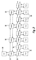
- FIG An electrical circuit is shown in FIG a generalization of the electrical circuit of the figure 1.
- Each of the first level distribution units 31, 32 is one Cascade of further distribution units arranged downstream.
- the distribution unit 31 with a Distribution unit 33 connected to which in turn several Distribution units 34 are connected in parallel.
- the Distribution units 33, 34 form one in this cascade second level.
- the number of distribution units 33, 34 in the second level of this cascade is again n. This number can also deviate from n.
- the distribution unit 31 of the The first level is suitable for the number n in this Cascade of the second level arranged distribution units 33, 34 to control.
- Each of the second level distribution units can have one Subsequent cascade of further distribution units his.
- the converters 35 are then connected to the distribution units of the last level.
- the distribution units 31, 32, 33, 34 and the converter 35 are constructed identically.
Landscapes
- Engineering & Computer Science (AREA)
- Power Engineering (AREA)
- Inverter Devices (AREA)
- Power Conversion In General (AREA)
- Supply And Distribution Of Alternating Current (AREA)
Applications Claiming Priority (2)
| Application Number | Priority Date | Filing Date | Title |
|---|---|---|---|
| DE10004504 | 2000-02-02 | ||
| DE10004504A DE10004504A1 (de) | 2000-02-02 | 2000-02-02 | Elektrische Schaltung zur Steuerung einer Mehrzahl parallelgeschalteter Umrichter |
Publications (3)
| Publication Number | Publication Date |
|---|---|
| EP1126592A2 true EP1126592A2 (fr) | 2001-08-22 |
| EP1126592A3 EP1126592A3 (fr) | 2003-09-24 |
| EP1126592B1 EP1126592B1 (fr) | 2005-07-13 |
Family
ID=7629556
Family Applications (1)
| Application Number | Title | Priority Date | Filing Date |
|---|---|---|---|
| EP01102008A Expired - Lifetime EP1126592B1 (fr) | 2000-02-02 | 2001-01-30 | Circuit électrique pour commander une pluralité d'onduleurs connectés en parallèle |
Country Status (2)
| Country | Link |
|---|---|
| EP (1) | EP1126592B1 (fr) |
| DE (2) | DE10004504A1 (fr) |
Families Citing this family (1)
| Publication number | Priority date | Publication date | Assignee | Title |
|---|---|---|---|---|
| DE10354130B4 (de) * | 2003-11-19 | 2018-06-21 | Sew-Eurodrive Gmbh & Co Kg | Umrichter und Baureihe von Umrichtern |
Family Cites Families (3)
| Publication number | Priority date | Publication date | Assignee | Title |
|---|---|---|---|---|
| IT1185262B (it) * | 1985-07-16 | 1987-11-04 | Italtel Spa | Disposizione circuitale per la sincronizzazione di un complesso di unita' di alimentazione |
| DE3840806A1 (de) * | 1988-11-29 | 1990-05-31 | Licentia Gmbh | Schaltungsanordnung zur parallelschaltung einer beliebigen anzahl von pulswechselrichtern |
| US5757634A (en) * | 1996-12-24 | 1998-05-26 | Siemans Electric Limited | Multiparalleling system of voltage source power converters |
-
2000
- 2000-02-02 DE DE10004504A patent/DE10004504A1/de not_active Ceased
-
2001
- 2001-01-30 DE DE50106711T patent/DE50106711D1/de not_active Expired - Lifetime
- 2001-01-30 EP EP01102008A patent/EP1126592B1/fr not_active Expired - Lifetime
Also Published As
| Publication number | Publication date |
|---|---|
| DE10004504A1 (de) | 2001-08-23 |
| EP1126592A3 (fr) | 2003-09-24 |
| DE50106711D1 (de) | 2005-08-18 |
| EP1126592B1 (fr) | 2005-07-13 |
Similar Documents
| Publication | Publication Date | Title |
|---|---|---|
| EP2596980B1 (fr) | Convertisseur de courant à plusieurs points avec hacheur de freinage | |
| EP1055275A1 (fr) | Procedes et dispositifs de fonctionnement en parallele commande de transformateurs de tension continue | |
| EP0597561B1 (fr) | Système de transfert pour l'échange de données | |
| EP2387820B1 (fr) | Dispositif convertisseur et procédé de commande d'un dispositif convertisseur | |
| EP2654190A2 (fr) | Procédé de fonctionnement dýune commutation électrique | |
| DE2508013A1 (de) | Vorrichtung zur stufenweisen schaltung der sekundaerspannung eines transformators | |
| EP0633662A1 (fr) | Montage pour un oscillateur en anneau | |
| DE102013108910B4 (de) | Elektromagnetventilsteuervorrichtung | |
| EP0399139A2 (fr) | Méthode d'extension d'un champ de couplage régulier à trois étages | |
| EP0113379B1 (fr) | Coupleur pour processeurs | |
| EP1126592B1 (fr) | Circuit électrique pour commander une pluralité d'onduleurs connectés en parallèle | |
| DE102022129313B3 (de) | Master-slave-kommunikationssystem für einphasige bis mehrphasige wechselstromversorgungen | |
| DE2900587B2 (de) | Decodierschaltung | |
| DE29915862U1 (de) | Speicherprogrammierbares Steuerungssystem | |
| EP3890177B1 (fr) | Dispositif de commande pour un convertisseur indirect et un convertisseur indirect | |
| DE68915211T2 (de) | Standardzelle. | |
| DE102011085559A1 (de) | Spannungswandler mit einer ersten Parallelschaltung | |
| CH650111A5 (de) | Vorrichtung fuer kuenstlichen nachhall. | |
| DE2057546A1 (de) | Signalschalteinrichtung | |
| EP2388471A1 (fr) | Dispositif de commutation séquentielle pour de interrupteurs avec un moyen de répartition d'impulsions de déclenchement | |
| DE2724110C2 (de) | Quasi-Zufallsgenerator | |
| DE102018219495A1 (de) | Fahrzeugsitz mit einer mindestens zwei Lüfter umfassenden Belüftungseinrichtung | |
| DE2645168A1 (de) | Leicht erweiterbares koppelfeld | |
| EP1473821B1 (fr) | Convertisseur de source de tension | |
| EP0244605A2 (fr) | Module de réseau logique fabriqué en technologie des circuits intégrés pour la construction de ces derniers |
Legal Events
| Date | Code | Title | Description |
|---|---|---|---|
| PUAI | Public reference made under article 153(3) epc to a published international application that has entered the european phase |
Free format text: ORIGINAL CODE: 0009012 |
|
| AK | Designated contracting states |
Kind code of ref document: A2 Designated state(s): AT BE CH CY DE DK ES FI FR GB GR IE IT LI LU MC NL PT SE TR |
|
| AX | Request for extension of the european patent |
Free format text: AL;LT;LV;MK;RO;SI |
|
| PUAL | Search report despatched |
Free format text: ORIGINAL CODE: 0009013 |
|
| AK | Designated contracting states |
Kind code of ref document: A3 Designated state(s): AT BE CH CY DE DK ES FI FR GB GR IE IT LI LU MC NL PT SE TR |
|
| AX | Request for extension of the european patent |
Extension state: AL LT LV MK RO SI |
|
| 17P | Request for examination filed |
Effective date: 20031017 |
|
| 17Q | First examination report despatched |
Effective date: 20040211 |
|
| AKX | Designation fees paid |
Designated state(s): DE ES FI FR GB IT |
|
| GRAP | Despatch of communication of intention to grant a patent |
Free format text: ORIGINAL CODE: EPIDOSNIGR1 |
|
| GRAS | Grant fee paid |
Free format text: ORIGINAL CODE: EPIDOSNIGR3 |
|
| GRAA | (expected) grant |
Free format text: ORIGINAL CODE: 0009210 |
|
| AK | Designated contracting states |
Kind code of ref document: B1 Designated state(s): DE ES FI FR GB IT |
|
| PG25 | Lapsed in a contracting state [announced via postgrant information from national office to epo] |
Ref country code: IT Free format text: LAPSE BECAUSE OF FAILURE TO SUBMIT A TRANSLATION OF THE DESCRIPTION OR TO PAY THE FEE WITHIN THE PRE;WARNING: LAPSES OF ITALIAN PATENTS WITH EFFECTIVE DATE BEFORE 2007 MAY HAVE OCCURRED AT ANY TIME BEFORE 2007. THE CORRECT EFFECTIVE DATE MAY BE DIFFERENT FROM THE ONE RECORDED.SCRIBED TIME-LIMIT Effective date: 20050713 Ref country code: FI Free format text: LAPSE BECAUSE OF FAILURE TO SUBMIT A TRANSLATION OF THE DESCRIPTION OR TO PAY THE FEE WITHIN THE PRESCRIBED TIME-LIMIT Effective date: 20050713 |
|
| REG | Reference to a national code |
Ref country code: GB Ref legal event code: FG4D Free format text: NOT ENGLISH |
|
| GBT | Gb: translation of ep patent filed (gb section 77(6)(a)/1977) |
Effective date: 20050713 |
|
| REF | Corresponds to: |
Ref document number: 50106711 Country of ref document: DE Date of ref document: 20050818 Kind code of ref document: P |
|
| PG25 | Lapsed in a contracting state [announced via postgrant information from national office to epo] |
Ref country code: ES Free format text: LAPSE BECAUSE OF FAILURE TO SUBMIT A TRANSLATION OF THE DESCRIPTION OR TO PAY THE FEE WITHIN THE PRESCRIBED TIME-LIMIT Effective date: 20051024 |
|
| ET | Fr: translation filed | ||
| PLBE | No opposition filed within time limit |
Free format text: ORIGINAL CODE: 0009261 |
|
| STAA | Information on the status of an ep patent application or granted ep patent |
Free format text: STATUS: NO OPPOSITION FILED WITHIN TIME LIMIT |
|
| 26N | No opposition filed |
Effective date: 20060418 |
|
| REG | Reference to a national code |
Ref country code: GB Ref legal event code: 732E |
|
| REG | Reference to a national code |
Ref country code: FR Ref legal event code: TP |
|
| REG | Reference to a national code |
Ref country code: DE Ref legal event code: R082 Ref document number: 50106711 Country of ref document: DE Representative=s name: RUEGER, BARTHELT & ABEL PATENTANWAELTE, DE Ref country code: DE Ref legal event code: R082 Ref document number: 50106711 Country of ref document: DE Representative=s name: RUEGER ABEL PATENT- UND RECHTSANWAELTE, DE |
|
| REG | Reference to a national code |
Ref country code: FR Ref legal event code: PLFP Year of fee payment: 16 |
|
| REG | Reference to a national code |
Ref country code: FR Ref legal event code: PLFP Year of fee payment: 17 |
|
| PGFP | Annual fee paid to national office [announced via postgrant information from national office to epo] |
Ref country code: DE Payment date: 20170125 Year of fee payment: 17 Ref country code: FR Payment date: 20170125 Year of fee payment: 17 |
|
| PGFP | Annual fee paid to national office [announced via postgrant information from national office to epo] |
Ref country code: GB Payment date: 20170127 Year of fee payment: 17 |
|
| REG | Reference to a national code |
Ref country code: DE Ref legal event code: R119 Ref document number: 50106711 Country of ref document: DE |
|
| GBPC | Gb: european patent ceased through non-payment of renewal fee |
Effective date: 20180130 |
|
| PG25 | Lapsed in a contracting state [announced via postgrant information from national office to epo] |
Ref country code: FR Free format text: LAPSE BECAUSE OF NON-PAYMENT OF DUE FEES Effective date: 20180131 Ref country code: DE Free format text: LAPSE BECAUSE OF NON-PAYMENT OF DUE FEES Effective date: 20180801 |
|
| REG | Reference to a national code |
Ref country code: FR Ref legal event code: ST Effective date: 20180928 |
|
| PG25 | Lapsed in a contracting state [announced via postgrant information from national office to epo] |
Ref country code: GB Free format text: LAPSE BECAUSE OF NON-PAYMENT OF DUE FEES Effective date: 20180130 |