EP1126631A2 - Système à diversité d'antennes avec sommation des signaux d' antennes contrôlés en phase - Google Patents
Système à diversité d'antennes avec sommation des signaux d' antennes contrôlés en phase Download PDFInfo
- Publication number
- EP1126631A2 EP1126631A2 EP01101770A EP01101770A EP1126631A2 EP 1126631 A2 EP1126631 A2 EP 1126631A2 EP 01101770 A EP01101770 A EP 01101770A EP 01101770 A EP01101770 A EP 01101770A EP 1126631 A2 EP1126631 A2 EP 1126631A2
- Authority
- EP
- European Patent Office
- Prior art keywords
- signal
- phase
- antenna
- fault
- antenna diversity
- Prior art date
- Legal status (The legal status is an assumption and is not a legal conclusion. Google has not performed a legal analysis and makes no representation as to the accuracy of the status listed.)
- Granted
Links
Images


Classifications
-
- H—ELECTRICITY
- H04—ELECTRIC COMMUNICATION TECHNIQUE
- H04B—TRANSMISSION
- H04B7/00—Radio transmission systems, i.e. using radiation field
- H04B7/02—Diversity systems; Multi-antenna system, i.e. transmission or reception using multiple antennas
-
- H—ELECTRICITY
- H04—ELECTRIC COMMUNICATION TECHNIQUE
- H04B—TRANSMISSION
- H04B7/00—Radio transmission systems, i.e. using radiation field
- H04B7/02—Diversity systems; Multi-antenna system, i.e. transmission or reception using multiple antennas
- H04B7/04—Diversity systems; Multi-antenna system, i.e. transmission or reception using multiple antennas using two or more spaced independent antennas
- H04B7/08—Diversity systems; Multi-antenna system, i.e. transmission or reception using multiple antennas using two or more spaced independent antennas at the receiving station
- H04B7/0868—Hybrid systems, i.e. switching and combining
- H04B7/0874—Hybrid systems, i.e. switching and combining using subgroups of receive antennas
-
- H—ELECTRICITY
- H04—ELECTRIC COMMUNICATION TECHNIQUE
- H04B—TRANSMISSION
- H04B7/00—Radio transmission systems, i.e. using radiation field
- H04B7/02—Diversity systems; Multi-antenna system, i.e. transmission or reception using multiple antennas
- H04B7/04—Diversity systems; Multi-antenna system, i.e. transmission or reception using multiple antennas using two or more spaced independent antennas
- H04B7/08—Diversity systems; Multi-antenna system, i.e. transmission or reception using multiple antennas using two or more spaced independent antennas at the receiving station
- H04B7/0802—Diversity systems; Multi-antenna system, i.e. transmission or reception using multiple antennas using two or more spaced independent antennas at the receiving station using antenna selection
- H04B7/0805—Diversity systems; Multi-antenna system, i.e. transmission or reception using multiple antennas using two or more spaced independent antennas at the receiving station using antenna selection with single receiver and antenna switching
- H04B7/0814—Diversity systems; Multi-antenna system, i.e. transmission or reception using multiple antennas using two or more spaced independent antennas at the receiving station using antenna selection with single receiver and antenna switching based on current reception conditions, e.g. switching to different antenna when signal level is below threshold
-
- H—ELECTRICITY
- H04—ELECTRIC COMMUNICATION TECHNIQUE
- H04B—TRANSMISSION
- H04B7/00—Radio transmission systems, i.e. using radiation field
- H04B7/02—Diversity systems; Multi-antenna system, i.e. transmission or reception using multiple antennas
- H04B7/04—Diversity systems; Multi-antenna system, i.e. transmission or reception using multiple antennas using two or more spaced independent antennas
- H04B7/08—Diversity systems; Multi-antenna system, i.e. transmission or reception using multiple antennas using two or more spaced independent antennas at the receiving station
- H04B7/0837—Diversity systems; Multi-antenna system, i.e. transmission or reception using multiple antennas using two or more spaced independent antennas at the receiving station using pre-detection combining
- H04B7/084—Equal gain combining, only phase adjustments
-
- H—ELECTRICITY
- H04—ELECTRIC COMMUNICATION TECHNIQUE
- H04B—TRANSMISSION
- H04B7/00—Radio transmission systems, i.e. using radiation field
- H04B7/02—Diversity systems; Multi-antenna system, i.e. transmission or reception using multiple antennas
- H04B7/04—Diversity systems; Multi-antenna system, i.e. transmission or reception using multiple antennas using two or more spaced independent antennas
- H04B7/08—Diversity systems; Multi-antenna system, i.e. transmission or reception using multiple antennas using two or more spaced independent antennas at the receiving station
- H04B7/0802—Diversity systems; Multi-antenna system, i.e. transmission or reception using multiple antennas using two or more spaced independent antennas at the receiving station using antenna selection
- H04B7/0831—Compensation of the diversity switching process for non-uniform properties or faulty operations of the switches used in the diversity switching process
Definitions
- the invention relates to an antenna diversity system for receiving the frequency-modulated Broadcasting with phase controlled summation of antenna signals for vehicles with a Multi-antenna system with at least two antenna output signals and a receiving device with one input each for a first and a second received signal path, of which the second of the two received signal paths is controlled by a phase control device Contains phase rotator, at the output of the received signal the same phase has as in the first branch and the two received signals in phase in a summation element are summed and the summed signal is fed to frequency demodulation.
- Antenna diversity systems of this type are preferably used for VHF radio reception and have long been known, for example from US4079318 and from US Pat. No. 5,517,696. These diversity systems aim to achieve a larger useful signal by superimposing two or more antenna signals in phase than with a single antenna, so as to reduce the likelihood of level drops in the area with multipath propagation. This results in a more favorable signal-to-noise ratio on average in relation to the receiver noise in the sum signal.
- the flawless mode of operation of such an antenna diversity system is, however, limited to the fact that the partial waves (Rayleigh reception field) which overlap at the receiving location differ only slightly in their instantaneous frequency, so that there are no audible reception disturbances. In reception situations, such as those shown in Fig.
- the received partial waves are no longer of the same frequency and lead to frequency interference due to the overlay, which after frequency demodulation during the Driving often lead to spontaneous noise.
- the wave bundles with the different transit times overlap at the receiving location in accordance with a Rayleigh distribution, which has different effects on the different antennas on the vehicle, so that the antenna signals of two diversity antennas on the vehicle can also have different instantaneous frequencies, particularly in the area of level fading.
- the difference between these frequencies is caused by the frequency modulation of the high-frequency carrier and is usually very large and the resulting phase difference would have to be corrected by the phase shifter in the second signal path if the signal in the first signal path has no frequency interference.
- the object of the invention is therefore in an antenna diversity system according to the preamble of claim 1 to avoid these disadvantages, the number of effective antenna signals inexpensively increase and thereby improve diversity efficiency.
- a particularly important advantage that comes with the invention is the applicability of one Large number of antennas or antenna signals in the case of the limited number of phase-controlled ones Signal paths. This makes the probability of the occurrence of disturbed received signals drastically reduced.
- the extent of signal improvement achievable with the invention is explained in more detail below using an example.
- the necessary technical effort remains extremely low since it relies on electronic switching measures and intelligent Limited electronic circuits, which are inexpensive due to the highly integrated circuits can be used.
- this increase in system performance can be achieved without additional extremely complex frequency converters and phase locked loops.
- several phase-locked loops can only be adjusted with regard to their control properties difficult to control and complicate the system.
- the interference detector 18 in the present Invention as long as fault detection signals 38 are emitted after each switching operation, until the same and only undisturbed received signal is present at both inputs 31 and 32, which leads to an undisturbed summed signal 37 in the receiving device 4.
- Fig. 1 Reception situation in a wave field disturbed by multipath propagation.
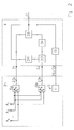
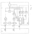
- Fig. 2 Antenna diversity system according to the invention with an antenna system with switching device 21, a receiving device 4 with signal path 1 31 and signal path 2 32 and a switching device 11, which all reception signals 23 simultaneously for both signal paths 31.32 can provide.
- a phase locked loop is located in the receiving device 4, consisting of a phase controller with low-pass character 34 and a phase shifter 33 for in-phase summation of the signals in the summation element 35.
- the summed output signal 37 is next to the FM receiver 1 on the one hand the phase controller with low-pass character 34 for phase control and the other a fault detector 18 for fast Fault detection fed in, so that with the fault detection signal 38 via switching device 11
- Another received signal 23 is assigned to at least one of the two signal paths 31, 32 becomes.
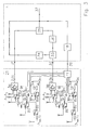
- Fig. 4 Arrangement as in Fig. 2 with signal summation in the intermediate frequency range according to Mixers 2 of the receiving device 4 controlled by the common oscillator 6 with a Signal evaluation processor 26, in which a fault detector 18, a timer 27 for detection the time intervals between occurring faults and a logic circuit 14 for control the switching device 11 and for switching from the phase mode to the scanning mode are included. Switching takes place by disconnecting one of the two signal paths with the signal path switch 16 and decommissioning the phase controller with low-pass character 34 through the phase control signal 25 in the event of excessive interference in the summed output signal 37 the system switches to a sufficiently low frequency of interference in the output signal 37 in the scanning mode back to live mode.
- phase mode is with the help of logic circuit 14 in the event of excessive interference in the summed output signal 37 switched to the scanning mode and in the signal path 31 a received signal 23a switched on with high priority from a priority list.
- the latter is in signal path 2 sequential switching on and checking the frequency of interference stored all available reception signal 23b stored in the logic circuit 14 and continuously updated.
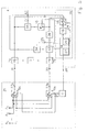
- Fig. 6 arrangement as in Fig. 5, but with a fault detector with better resolution 18b and accurate ranking of the received signals 23b in the priority list and a fault detector with extremely fast display 18a to avoid too long test times in the sum signal path 43 and the associated audible interference.
- Fig. 7 arrangement as in Fig. 6, but with two separate fault detectors with better Resolution 18b, c for the purpose of the permanent availability of the fault display signal 10 for Improved the priority list in scanning mode and improved display of the better Signals in phase mode.
- Fig. 8 Arrangement according to the invention with a receiving device 4, each with an I-frequency converter 44 and a Q frequency converter 45 in the two signal paths 1, 2 31,32 and summation elements 35 for the regression of the frequency-modulated signals in the Signal paths 1,2 31,32 and in the sum signal path 43 for fast detection of the disturbance analogue fault detectors 18.
- the phase shift is carried out by separate evaluation of the intermediate frequency I and Q signals in the phase rotator 33.
- the DSP 41 the Signals ⁇ Q and ⁇ I separately digitized and the phase shifter 33 from the phase controller with a low-pass character 34 preferably controlled digitally.
- the basic arrangement of a diversity antenna system according to the invention is shown in FIG. 2 shown.
- the receiving device 4 has a first signal path 31 and a second signal path 32, in which a phase rotator is switched on.
- transmission block 36 according to the prior art, the signal in the second received signal path with an auxiliary modulation acted upon, with the help of the phase rotating device 33 by a phase control device 34 is controlled such that at the output of the summation element 35 the signals in first reception path and in the second reception path are summed in phase.
- the Multi-antenna system 21 contains controllable switches 5, with the help of which, depending on the Switch positions of the controllable switches 5 signals 23a and 23b on the first 31 and the second 32 received signal path.
- this signal is a fault detector 18 to extremely quickly Detection of the sum signal disturbed by frequency interference stroke, its interference detection signal 38 in turn is fed to a controllable logic switching device 11 which is in the multi-antenna system 21 by choosing a different switching position Switches 5a and 5b receive another signal at at least one of the inputs 31 and 32, respectively supplies. The rapid switching of the switches 5a and 5b causes the phase-locked loop first comes out of step.
- phase control device 34 the character of a low-pass transfer function, i.e.
- the maximum phase change speed must be set so that it is also in the capture range the phase control can result in no audible frequency interference.
- the phase control speed must not be limited so that the speed during a trip phase changes resulting from the Rayleigh reception field of those undisturbed in the frequency swing Signals 23a and 23b of the phase locked loop of the required phase change in-phase superimposition of the signals in the summation element 35 can no longer follow.
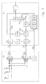
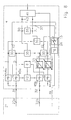
- FIG. 3 shows a more complex and generally designed multi-antenna system 21, with the help of switching impedances 7a to 7d using switches 8a to 8d the most varied signal pairs 23a and 23b are fed to the received signal paths 31 and 33, respectively become.
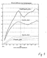
- the diversity efficiency is a pure one Scanning diversity systems with the same two antennas from the curve ScanDiv_2Ant.
- the curve labeled ScanDiv_4Ant in FIG. 9 describes the diversity efficiency of the four antennas extended and arranged in a line antenna group. From this it can be seen that by making several antennas available, the diversity efficiency increases significantly and almost reach the numerical number of antennas at sufficiently large distances can.
- the improvement that can be achieved with the device according to the present invention beyond the state of the art is described, for example, for the antenna group described in FIG. 9 by the one with ScanPhaseDiv_4 Ant.
- the diversity efficiency can be increased by the value 1.5 by using the invention.
- Similar improvements can also be achieved with 4 antennas arranged compactly on the window pane of a motor vehicle, whose different reception behavior, despite the proximity to one another, results from the different interaction with the vehicle body.
- due to the reduced disturbances in the summed output signal 37 there is a reduction in the switching frequency effective there and, as a result, a subjectively perceived quieter FM reception if the invention, as shown below, is advantageously designed.
- the desired improvement in the signal-to-noise ratio results from the in-phase superimposition of the useful signals in the two signal paths.
- the present invention can also be applied to all known diversity systems with phase control, that is to say to systems with maximum ratio control or very generally with control of the phase with regard to an optimum useful-to-noise ratio in the summed output signal 37, also with regard to adjacent channel and co-channel interference.
- the upper limit frequency for the phase control signal 25 has been found in existing systems about 50 Hz has proven to be favorable for reception in the FM radio range. So that is the control time TE is not less than approx. 20 ms.
- the present invention takes advantage of the fact that in the antenna system with switching device 21, a larger number than two received signals Are available. In reception areas with poor supply i.e. with a high frequency of interference in the individual antenna signals and thus also in each of two of these antenna signals The sum signal formed provides the in-phase summation of such signals practically none Advantage. Because in these areas there is between successive fault displays for the Loop does not settle enough time.
- Invention between the phase mode with the assignment of different antennas after the strategies described below and the pure scanning mode. If the antenna system is started in scanning mode, i.e. the signal path 2 in Fig. 4 by Opening of the signal path switch 16 is switched off, then the Phase controller with low-pass character 34 shut down and the FM receiver 1 receives at the output of the summation element 35 exclusively the received signal 23a. When a malfunction occurs in the summed output signal 37, an address signal 39 is generated via the logic circuit 14, which switches through another receiving signal 23a via the switching device 11.
- the activation time TA is as Criterion selected time TASP reached, the signal path 2 32 by closing the signal path switch 16 switched on, the phase controller with low-pass character 34 by release activated by the phase control signal 25 and thus the phase locked loop closed. Because of the phase-locked loop can test the sufficiently low frequency of faults, tested with the help of TA settle in. This settling can be done with any pair of available reception signals 23 take place. The optimal selection of the two signal paths 1,2 31,32 supplied Receive signals 23 from the available receive signals will be described below.
- the timer 27 activated and via the logic circuit 14 and the switching device 11 initially successively at least one of the received signals 23 replaced.
- the activation time becomes with each occurrence of the fault detection signal 38 TA determined for the switched pair of received signals 23.
- a predetermined activation time TAPS which is also preferably selected 5-10 times TE is.
- the arrangements in FIGS. 5 - 8 pursued a strategy in scanning mode in such a way that with the help of the switched off Signal path 2 by alternately switching on the available reception signals 23b the frequency of interference of the individual signals and a priority list in the logic circuit 14 with regard to the interference purity of the received signals 23b.
- the priority list is always updated before operating in scanning mode. If the TASP criterion for switching from scanning mode to phase mode is met, then according to the invention those signals are the signal paths 1 31 and 2 32 via the Switching device 11 assigned, which lead the priority list. The system can therefore use the best two signals in phase mode.
- the reception disturbances in the reception signals 23a and 23b are determined separately and when a fault occurs in the summed output signal 37 the worse of the two received signals 23a and 23b by another available one Receive signal 23 are exchanged. This exchange usually takes place entirely without disturbing the output signal 37.
- this method using the signal path selector 15, which is controlled by a clock generator 29 located in the logic circuit 14.
- the fault detector 18 alternately between the switching position 1 in the scanning mode and S for checking the received signal 23 in signal path 2 and the received signal 23 in summed output signal 37 switched by the clock 29.
- the clock 29 switches these signals each over a necessary test time to the fault detector 18, so that in the Logic circuit 14, an address signal 39 is sent, whereby on the one hand when there is a Disturbance in the summed output signal 37 there is a switchover of the received signal 23a and on the other hand, by checking the received signal 23b in the signal path 2, the priority list for the available reception signals 23 is updated.
- the signal path selector 15 which realizes as a fault detector with extremely fast display 18a is the elaborate use of several fault detectors 18 avoided. If the TASP criterion switches the system into phase mode and the two signal paths 31, 32 receive those reception signals 23 which have the highest or high priority updated in the list of logic circuit 14. In phase mode, the signal path selector 15 sequentially in each case over the necessary test time of the fault detector 18 the three switch positions, so that in this mode the frequency of interference both of the individual signals of the two signal paths and of the summed output signal 37 is present in the logic circuit 14. If a fault occurs in the summed output signal 37 the signal is then exchanged in the signal path, which has the greater frequency of interference owns. To avoid audible interference, the interference detection time of the interference detector should be used 18 should not be significantly larger than 50 ⁇ s.
- the test of the summed output signal 37 must with the necessary short test time with the help of the fault detector with extremely fast display 18a become. After switching the system into phase mode, the receive signals 23 in the two signal paths 1, 2 31, 32 sequentially by switching the signal path selector 15 checked.
- quadrature modulators are often used for frequency conversion used. 8 is in the receiving device, each with an I-frequency converter 44a, 44b and a Q frequency converter 45a, 45b, which are from a common oscillator 6 can be controlled and the control of the Q-frequency converter via a 90 ° phase shifter 42 takes place.
- the intermediate frequency I and Q signals are used in modern receiver concepts processed in a digital processor 41 (DSP). Because of the currently bit rate in such a processor may still be necessary extremely fast displaying fault detector 18 as an analog element and to be arranged in the analog range of the receiver.
- Obtaining the full frequency modulated intermediate frequency signal takes place in both signal paths 31, 32 with the aid of the summation elements 35, the outputs of which are connected to terminals 1 and 2 in signal path selector 15 are.
- a further summation element is used to form the summed output signal 37 35 available, in which the signals undI and the signals ⁇ Q are added and the Terminal S of the signal path selector 15 are supplied.
- the regulation of the phase in the signal path 2 32 is done by amplitude weighting elements 46a, 46b, which are preferably from the DSP 41 can be controlled to regulate the phase. Because of the relatively slow control processes the phase can also be set with a limited data rate of the DSP 41.
Landscapes
- Engineering & Computer Science (AREA)
- Computer Networks & Wireless Communication (AREA)
- Signal Processing (AREA)
- Radio Transmission System (AREA)
Applications Claiming Priority (2)
| Application Number | Priority Date | Filing Date | Title |
|---|---|---|---|
| DE10007301 | 2000-02-17 | ||
| DE10007301 | 2000-02-17 |
Publications (3)
| Publication Number | Publication Date |
|---|---|
| EP1126631A2 true EP1126631A2 (fr) | 2001-08-22 |
| EP1126631A3 EP1126631A3 (fr) | 2003-04-02 |
| EP1126631B1 EP1126631B1 (fr) | 2003-08-20 |
Family
ID=7631340
Family Applications (1)
| Application Number | Title | Priority Date | Filing Date |
|---|---|---|---|
| EP01101770A Expired - Lifetime EP1126631B1 (fr) | 2000-02-17 | 2001-01-26 | Système à diversité d'antennes avec sommation des signaux d' antennes contrôlés en phase |
Country Status (7)
| Country | Link |
|---|---|
| US (1) | US6925293B2 (fr) |
| EP (1) | EP1126631B1 (fr) |
| JP (1) | JP2001267988A (fr) |
| KR (1) | KR100418284B1 (fr) |
| AT (1) | ATE247880T1 (fr) |
| DE (2) | DE10102616A1 (fr) |
| ES (1) | ES2204759T3 (fr) |
Cited By (3)
| Publication number | Priority date | Publication date | Assignee | Title |
|---|---|---|---|---|
| EP1798870A2 (fr) | 2005-12-15 | 2007-06-20 | FUBA Automotive GmbH & Co. KG | Dispositif de réception avec mise en phase des signaux d'antenne |
| DE102007039914A1 (de) | 2007-08-01 | 2009-02-05 | Lindenmeier, Heinz, Prof. Dr. Ing. | Antennendiversityanlage mit zwei Antennen für den Funkempfang in Fahrzeugen |
| US7936852B2 (en) | 2005-09-12 | 2011-05-03 | Delphi Delco Electronics Europe Gmbh | Antenna diversity system for radio reception for motor vehicles |
Families Citing this family (37)
| Publication number | Priority date | Publication date | Assignee | Title |
|---|---|---|---|---|
| DE19916855A1 (de) * | 1999-04-14 | 2000-10-26 | Heinz Lindenmeier | Funktelefonanlage mit Gruppenantenne für Fahrzeuge |
| ATE323978T1 (de) * | 2001-03-02 | 2006-05-15 | Fuba Automotive Gmbh | Diversity-anlage zum empfang digitaler terrestrischer und/oder satelliten-funksignale für fahrzeuge |
| US7155192B2 (en) * | 2001-09-25 | 2006-12-26 | At&T Corp. | Multi-antenna/multi-receiver array diversity system |
| US7340236B2 (en) * | 2002-08-07 | 2008-03-04 | Texas Instruments Incorporated | System for operational coexistence of wireless communication technologies |
| DE10304431A1 (de) | 2003-02-04 | 2004-08-05 | Lindenmeier, Heinz, Prof. Dr.-Ing. | Scanning-Antennen-Diversitysystem für den FM-Hörrundfunk für Fahrzeuge |
| US7006809B2 (en) | 2003-05-06 | 2006-02-28 | Ami Semiconductor, Inc. | Adaptive diversity receiver architecture |
| DE10337717A1 (de) * | 2003-08-16 | 2005-03-17 | Leopold Kostal Gmbh & Co Kg | Hochfrequenzfunkeinrichtung für Kraftfahrzeuge |
| US7376406B2 (en) * | 2004-04-16 | 2008-05-20 | Matsushita Electric Industrial Co., Ltd. | Diversity reception apparatus |
| JP4323381B2 (ja) * | 2004-06-03 | 2009-09-02 | Okiセミコンダクタ株式会社 | 無線受信装置 |
| DE102004045109A1 (de) * | 2004-09-17 | 2006-03-23 | Robert Bosch Gmbh | Verfahren zum mobilen Empfangen eines, insbesondere frequenzmodulierten, Funksignals und Funkempfänger-Schaltung hierfür |
| EP1657830B1 (fr) * | 2004-11-15 | 2008-06-18 | Harman/Becker Automotive Systems GmbH | Système radio et procédé pour contrôler un système radio |
| KR100672582B1 (ko) * | 2004-11-22 | 2007-01-24 | 엘지전자 주식회사 | 디지털 멀티미디어 방송 수신 장치 및 이를 이용한 신호처리 방법 |
| US20060292986A1 (en) * | 2005-06-27 | 2006-12-28 | Yigal Bitran | Coexistent bluetooth and wireless local area networks in a multimode terminal and method thereof |
| US20080096509A1 (en) * | 2006-10-19 | 2008-04-24 | Maxlinear, Inc. | Low Complexity Diversity Receiver |
| DE102007017478A1 (de) * | 2007-04-13 | 2008-10-16 | Lindenmeier, Heinz, Prof. Dr. Ing. | Empfangsanlage mit einer Schaltungsanordnung zur Unterdrückung von Umschaltstörungen bei Antennendiversity |
| EP2037593A3 (fr) * | 2007-07-10 | 2016-10-12 | Delphi Delco Electronics Europe GmbH | Installation de diversité d'antennes pour la réception radio à bande relativement large dans des véhicules |
| DE102008003532A1 (de) * | 2007-09-06 | 2009-03-12 | Lindenmeier, Heinz, Prof. Dr. Ing. | Antenne für den Satellitenempfang |
| JP4941338B2 (ja) * | 2008-02-01 | 2012-05-30 | 富士通株式会社 | 通信装置、ノイズ除去方法及びコンピュータプログラム |
| US8494466B2 (en) | 2008-03-26 | 2013-07-23 | Broadcom Corporation | Selecting receiver chains of a mobile unit for receiving wireless signals |
| DE102008047937A1 (de) | 2008-09-18 | 2010-03-25 | Delphi Delco Electronics Europe Gmbh | Rundfunk-Empfangssystem |
| DE102008047978A1 (de) | 2008-09-18 | 2010-03-25 | Delphi Delco Electronics Europe Gmbh | Diversity-Empfangssystem |
| PT2209221T (pt) * | 2009-01-19 | 2018-12-27 | Fuba Automotive Electronics Gmbh | Sistema de recepção para a soma de sinais de antena em fase |
| DE102009011542A1 (de) * | 2009-03-03 | 2010-09-09 | Heinz Prof. Dr.-Ing. Lindenmeier | Antenne für den Empfang zirkular in einer Drehrichtung der Polarisation ausgestrahlter Satellitenfunksignale |
| DE102009023514A1 (de) * | 2009-05-30 | 2010-12-02 | Heinz Prof. Dr.-Ing. Lindenmeier | Antenne für zirkulare Polarisation mit einer leitenden Grundfläche |
| EP2443766A1 (fr) | 2009-06-15 | 2012-04-25 | Agc Automotive Americas R&D, Inc. | Système d'antenne et procédé d'optimisation d'un signal rf |
| US8355676B2 (en) * | 2009-11-17 | 2013-01-15 | Franklin Technologies, Llc | System and method for reducing radio frequency interference |
| US8817917B2 (en) | 2011-06-21 | 2014-08-26 | Ibiquity Digital Corporation | Method and apparatus for implementing signal quality metrics and antenna diversity switching control |
| US9154608B2 (en) * | 2012-05-09 | 2015-10-06 | Facebook, Inc. | Data exchange between antenna and modem of mobile device |
| WO2014149201A1 (fr) | 2013-03-15 | 2014-09-25 | Agc Automotive Americas R& D, Inc. | Ensemble fenêtre à régions transparentes ayant une fente d'amélioration de performance formée en son sein |
| GB2539732A (en) * | 2015-06-25 | 2016-12-28 | Airspan Networks Inc | A configurable antenna and method of operating such a configurable antenna |
| KR102456841B1 (ko) | 2016-01-04 | 2022-10-21 | 한국전자통신연구원 | 가시경로 상에서 다중입력 다중출력 시스템의 성능 향상 방법 |
| FR3070796B1 (fr) * | 2017-09-05 | 2019-08-30 | Continental Automotive France | Procede de mise a jour d'une liste de stations recevables par un systeme de reception radio |
| WO2020203875A1 (fr) * | 2019-03-29 | 2020-10-08 | 原田工業株式会社 | Dispositif de réduction de bruit |
| WO2021066520A1 (fr) * | 2019-10-02 | 2021-04-08 | 주식회사 케이엠더블유 | Appareil et procédé pour commander une qualité de signal d'une antenne |
| KR102737196B1 (ko) * | 2019-12-20 | 2024-12-04 | 현대자동차주식회사 | 차량 및 차량용 안테나 시스템 |
| CN116482498A (zh) * | 2023-04-27 | 2023-07-25 | 深圳唐为科技有限公司 | 在线检测信号分集接收装置与监控方法、可读存储介质 |
| CN116755058B (zh) * | 2023-05-26 | 2026-01-30 | 吉林大学 | 基于相位切换时间排序的opa控制方法 |
Family Cites Families (19)
| Publication number | Priority date | Publication date | Assignee | Title |
|---|---|---|---|---|
| US3593147A (en) * | 1969-03-04 | 1971-07-13 | Itt | Equal gain diversity receiving system with squelch |
| CA1088632A (fr) * | 1975-06-23 | 1980-10-28 | Nippon Eectric Co., Ltd. | Systeme de reception a diversite d'espace avec combinaison de signaux a phases asservies a un etage de frequence intermediaire |
| US4232339A (en) * | 1978-09-08 | 1980-11-04 | Harris Corporation | Television signal horizontal interval timing reconstruction system |
| DE3814900A1 (de) * | 1988-05-03 | 1989-11-23 | Hirschmann Richard Gmbh Co | Empfangsverfahren und empfangs-antennensystem fuer mobilen empfang |
| DE4204490B4 (de) * | 1992-02-14 | 2004-04-15 | Heinz Prof. Dr.-Ing. Lindenmeier | Schaltungsanordnung zur Unterdrückung von Umschaltstörungen bei Antennendiversity |
| JPH07154377A (ja) * | 1993-11-30 | 1995-06-16 | Nec Corp | ダイバーシティ受信機 |
| JPH07170203A (ja) * | 1993-12-14 | 1995-07-04 | Nec Corp | スペースダイバーシティのスケルチ方式 |
| JPH0846557A (ja) * | 1994-07-26 | 1996-02-16 | Alpine Electron Inc | アンテナダイバーシティシステム |
| US5517686A (en) * | 1994-09-29 | 1996-05-14 | Delco Electronics Corporation | Diversity receiver for FM stereo utilizing a pilot tone multiple for phase alignment of received signals |
| JPH08307297A (ja) * | 1995-05-02 | 1996-11-22 | Fujitsu Ten Ltd | 車載用アンテナ整合装置 |
| US5603107A (en) * | 1995-06-09 | 1997-02-11 | Ford Motor Company | Switching system for diversity antenna FM receiver |
| DE19607045A1 (de) * | 1996-02-24 | 1997-08-28 | Lindenmeier Heinz | Empfangsantennen-Scanningdiversitysystem für den Meterwellenbereich für Fahrzeuge |
| JPH09307491A (ja) * | 1996-05-20 | 1997-11-28 | Oki Electric Ind Co Ltd | ダイバーシティ受信回路 |
| JP3188398B2 (ja) * | 1996-07-26 | 2001-07-16 | 株式会社ヨコオ | 位相合成装置付アンテナ |
| US6009307A (en) * | 1997-05-13 | 1999-12-28 | Qualcomm Incorporated | Multiple antenna detecting and selecting |
| US6049705A (en) * | 1998-02-03 | 2000-04-11 | Ericsson Inc. | Diversity for mobile terminals |
| JP4181259B2 (ja) * | 1998-12-14 | 2008-11-12 | 松下電器産業株式会社 | 受信装置及び受信方法 |
| JP2000252895A (ja) * | 1999-02-26 | 2000-09-14 | Nippon Sheet Glass Co Ltd | 車載用tvダイバーシティシステム |
| JP3557969B2 (ja) * | 1999-11-24 | 2004-08-25 | 日本電気株式会社 | 無線受信装置およびキャリブレーション方法 |
-
2001
- 2001-01-20 DE DE10102616A patent/DE10102616A1/de not_active Withdrawn
- 2001-01-26 EP EP01101770A patent/EP1126631B1/fr not_active Expired - Lifetime
- 2001-01-26 AT AT01101770T patent/ATE247880T1/de not_active IP Right Cessation
- 2001-01-26 ES ES01101770T patent/ES2204759T3/es not_active Expired - Lifetime
- 2001-01-26 DE DE50100506T patent/DE50100506D1/de not_active Expired - Lifetime
- 2001-02-14 US US09/783,000 patent/US6925293B2/en not_active Expired - Lifetime
- 2001-02-15 JP JP2001038552A patent/JP2001267988A/ja active Pending
- 2001-02-17 KR KR10-2001-0007988A patent/KR100418284B1/ko not_active Expired - Fee Related
Cited By (7)
| Publication number | Priority date | Publication date | Assignee | Title |
|---|---|---|---|---|
| US7936852B2 (en) | 2005-09-12 | 2011-05-03 | Delphi Delco Electronics Europe Gmbh | Antenna diversity system for radio reception for motor vehicles |
| EP1763151A3 (fr) * | 2005-09-12 | 2013-05-29 | Delphi Delco Electronics Europe GmbH | Système à diversité d'antennes pour la réception dans des vehicules |
| DE102006039357B4 (de) | 2005-09-12 | 2018-06-28 | Heinz Lindenmeier | Antennendiversityanlage zum Funkempfang für Fahrzeuge |
| EP1798870A2 (fr) | 2005-12-15 | 2007-06-20 | FUBA Automotive GmbH & Co. KG | Dispositif de réception avec mise en phase des signaux d'antenne |
| EP1798870A3 (fr) * | 2005-12-15 | 2012-07-11 | Delphi Delco Electronics Europe GmbH | Dispositif de réception avec mise en phase des signaux d'antenne |
| DE102007039914A1 (de) | 2007-08-01 | 2009-02-05 | Lindenmeier, Heinz, Prof. Dr. Ing. | Antennendiversityanlage mit zwei Antennen für den Funkempfang in Fahrzeugen |
| EP2031767A2 (fr) | 2007-08-01 | 2009-03-04 | Delphi Delco Electronics Europe GmbH | Installation de diversité d'antennes dotée de deux antennes pour la réception radio dans des véhicules |
Also Published As
| Publication number | Publication date |
|---|---|
| US20010016478A1 (en) | 2001-08-23 |
| ATE247880T1 (de) | 2003-09-15 |
| ES2204759T3 (es) | 2004-05-01 |
| EP1126631B1 (fr) | 2003-08-20 |
| US6925293B2 (en) | 2005-08-02 |
| DE10102616A1 (de) | 2001-08-23 |
| KR100418284B1 (ko) | 2004-02-11 |
| KR20010082733A (ko) | 2001-08-30 |
| JP2001267988A (ja) | 2001-09-28 |
| EP1126631A3 (fr) | 2003-04-02 |
| DE50100506D1 (de) | 2003-09-25 |
Similar Documents
| Publication | Publication Date | Title |
|---|---|---|
| EP1126631B1 (fr) | Système à diversité d'antennes avec sommation des signaux d' antennes contrôlés en phase | |
| DE4101629C3 (de) | Antennendiversity-Anlage mit mindestens zwei Antennen für den mobilen Empfang von Meter- und Dezimeterwellen | |
| DE69527964T2 (de) | Phasengesteuerte gruppenantenne mit spread-spectrum-system und verfahren. | |
| EP0401221B1 (fr) | Procede de reception et systeme d'antennes receptrices pour la mise en oeuvre du procede | |
| DE102004006519B4 (de) | Antennenanordnungsverfahren und Radarvorrichtung | |
| EP0201977B1 (fr) | Dispositif de réception à diversité d'antenne destiné à éliminer des perturbations de réception | |
| EP1763151B1 (fr) | Système à diversité d'antennes pour la réception dans des vehicules | |
| DE69228650T2 (de) | FM-Empfänger mit zwei Zwischenfrequenz-Bandpass-Filtern | |
| WO2002041537A1 (fr) | Systeme d'antennes | |
| DE69936682T2 (de) | Basistation und Funkübertragungsverfahren mit Empfängsdiversität | |
| EP1021000B1 (fr) | Système d'antennes de balayage en diversité pour véhicules | |
| EP2037593A2 (fr) | Installation de diversité d'antennes pour la réception radio à bande relativement large dans des véhicules | |
| DE10304431A1 (de) | Scanning-Antennen-Diversitysystem für den FM-Hörrundfunk für Fahrzeuge | |
| EP1798870B1 (fr) | Dispositif de réception avec mise en phase des signaux d'antenne | |
| EP0270188B1 (fr) | Installation de diversité de signal pour la réception mobile | |
| EP0243885B1 (fr) | Procédé et dispositif d'établissement d'une communication dans un réseau radio à ondes courtes | |
| EP1256191A1 (fr) | Procede de selection d'antennes d'un dispositif de reception dans un system radio, en particulier dans un system de telephonie mobile | |
| DE19847887A1 (de) | Scanning-Antennen-Diversity-System für Fahrzeuge | |
| DE69834600T2 (de) | Drahtlose Vorrichtung für Hochleistungs-Übertragungsfunksignale | |
| EP2209221A2 (fr) | Installation de réception destinée à la sommation de signaux d'antennes phasés | |
| DE10220658B4 (de) | Fahrzeugradioempfänger und Verfahren zur Strahllenksteuerung von Radiosignalen in Fahrzeugradioempfängern | |
| EP1402656B1 (fr) | Systeme recepteur radio a plusieurs antennes et a plusieurs recepteurs | |
| EP0345843B1 (fr) | Méthode de réception et système d'antenne de réception pour réception mobile | |
| WO2004036781A1 (fr) | Dispositif et procede permettant de suivre un moment fixe d'echantillonnage dans des recepteurs radio | |
| EP1469614B1 (fr) | Récepteur radio avec diversité d'antennes et procédé utilisant ledit récepteur |
Legal Events
| Date | Code | Title | Description |
|---|---|---|---|
| PUAI | Public reference made under article 153(3) epc to a published international application that has entered the european phase |
Free format text: ORIGINAL CODE: 0009012 |
|
| AK | Designated contracting states |
Kind code of ref document: A2 Designated state(s): AT BE CH CY DE DK ES FI FR GB GR IE IT LI LU MC NL PT SE TR |
|
| AX | Request for extension of the european patent |
Free format text: AL;LT;LV;MK;RO;SI |
|
| PUAL | Search report despatched |
Free format text: ORIGINAL CODE: 0009013 |
|
| AK | Designated contracting states |
Designated state(s): AT BE CH CY DE DK ES FI FR GB GR IE IT LI LU MC NL PT SE TR Kind code of ref document: A3 Designated state(s): AT BE CH CY DE DK ES FI FR GB GR IE IT LI LU MC NL PT SE TR |
|
| AX | Request for extension of the european patent |
Extension state: AL LT LV MK RO SI |
|
| GRAH | Despatch of communication of intention to grant a patent |
Free format text: ORIGINAL CODE: EPIDOS IGRA |
|
| 17P | Request for examination filed |
Effective date: 20030305 |
|
| GRAH | Despatch of communication of intention to grant a patent |
Free format text: ORIGINAL CODE: EPIDOS IGRA |
|
| GRAA | (expected) grant |
Free format text: ORIGINAL CODE: 0009210 |
|
| AK | Designated contracting states |
Designated state(s): AT BE CH CY DE DK ES FI FR GB GR IE IT LI LU MC NL PT SE TR |
|
| AX | Request for extension of the european patent |
Extension state: AL LT LV MK RO SI |
|
| PG25 | Lapsed in a contracting state [announced via postgrant information from national office to epo] |
Ref country code: CY Free format text: LAPSE BECAUSE OF FAILURE TO SUBMIT A TRANSLATION OF THE DESCRIPTION OR TO PAY THE FEE WITHIN THE PRESCRIBED TIME-LIMIT Effective date: 20030820 Ref country code: NL Free format text: LAPSE BECAUSE OF FAILURE TO SUBMIT A TRANSLATION OF THE DESCRIPTION OR TO PAY THE FEE WITHIN THE PRESCRIBED TIME-LIMIT Effective date: 20030820 Ref country code: IE Free format text: LAPSE BECAUSE OF FAILURE TO SUBMIT A TRANSLATION OF THE DESCRIPTION OR TO PAY THE FEE WITHIN THE PRESCRIBED TIME-LIMIT Effective date: 20030820 Ref country code: FI Free format text: LAPSE BECAUSE OF FAILURE TO SUBMIT A TRANSLATION OF THE DESCRIPTION OR TO PAY THE FEE WITHIN THE PRESCRIBED TIME-LIMIT Effective date: 20030820 Ref country code: TR Free format text: LAPSE BECAUSE OF FAILURE TO SUBMIT A TRANSLATION OF THE DESCRIPTION OR TO PAY THE FEE WITHIN THE PRESCRIBED TIME-LIMIT Effective date: 20030820 |
|
| REG | Reference to a national code |
Ref country code: GB Ref legal event code: FG4D Free format text: NOT ENGLISH |
|
| REG | Reference to a national code |
Ref country code: CH Ref legal event code: EP |
|
| GBT | Gb: translation of ep patent filed (gb section 77(6)(a)/1977) | ||
| REG | Reference to a national code |
Ref country code: IE Ref legal event code: FG4D Free format text: GERMAN |
|
| REF | Corresponds to: |
Ref document number: 50100506 Country of ref document: DE Date of ref document: 20030925 Kind code of ref document: P |
|
| PG25 | Lapsed in a contracting state [announced via postgrant information from national office to epo] |
Ref country code: DK Free format text: LAPSE BECAUSE OF FAILURE TO SUBMIT A TRANSLATION OF THE DESCRIPTION OR TO PAY THE FEE WITHIN THE PRESCRIBED TIME-LIMIT Effective date: 20031120 Ref country code: GR Free format text: LAPSE BECAUSE OF FAILURE TO SUBMIT A TRANSLATION OF THE DESCRIPTION OR TO PAY THE FEE WITHIN THE PRESCRIBED TIME-LIMIT Effective date: 20031120 |
|
| REG | Reference to a national code |
Ref country code: SE Ref legal event code: TRGR |
|
| AKX | Designation fees paid |
Designated state(s): AT BE CH CY DE DK ES FI FR GB GR IE IT LI LU MC NL PT SE TR |
|
| PGFP | Annual fee paid to national office [announced via postgrant information from national office to epo] |
Ref country code: SE Payment date: 20040107 Year of fee payment: 4 |
|
| PG25 | Lapsed in a contracting state [announced via postgrant information from national office to epo] |
Ref country code: PT Free format text: LAPSE BECAUSE OF FAILURE TO SUBMIT A TRANSLATION OF THE DESCRIPTION OR TO PAY THE FEE WITHIN THE PRESCRIBED TIME-LIMIT Effective date: 20040120 |
|
| PGFP | Annual fee paid to national office [announced via postgrant information from national office to epo] |
Ref country code: ES Payment date: 20040123 Year of fee payment: 4 |
|
| LTIE | Lt: invalidation of european patent or patent extension |
Effective date: 20030820 |
|
| PG25 | Lapsed in a contracting state [announced via postgrant information from national office to epo] |
Ref country code: AT Free format text: LAPSE BECAUSE OF NON-PAYMENT OF DUE FEES Effective date: 20040126 Ref country code: LU Free format text: LAPSE BECAUSE OF NON-PAYMENT OF DUE FEES Effective date: 20040126 |
|
| PG25 | Lapsed in a contracting state [announced via postgrant information from national office to epo] |
Ref country code: BE Free format text: LAPSE BECAUSE OF NON-PAYMENT OF DUE FEES Effective date: 20040131 Ref country code: MC Free format text: LAPSE BECAUSE OF NON-PAYMENT OF DUE FEES Effective date: 20040131 |
|
| NLV1 | Nl: lapsed or annulled due to failure to fulfill the requirements of art. 29p and 29m of the patents act | ||
| REG | Reference to a national code |
Ref country code: IE Ref legal event code: FD4D |
|
| REG | Reference to a national code |
Ref country code: ES Ref legal event code: FG2A Ref document number: 2204759 Country of ref document: ES Kind code of ref document: T3 |
|
| ET | Fr: translation filed | ||
| PLBE | No opposition filed within time limit |
Free format text: ORIGINAL CODE: 0009261 |
|
| STAA | Information on the status of an ep patent application or granted ep patent |
Free format text: STATUS: NO OPPOSITION FILED WITHIN TIME LIMIT |
|
| BERE | Be: lapsed |
Owner name: *FUBA AUTOMOTIVE G.M.B.H. & CO. K.G. Effective date: 20040131 |
|
| 26N | No opposition filed |
Effective date: 20040524 |
|
| PG25 | Lapsed in a contracting state [announced via postgrant information from national office to epo] |
Ref country code: GB Free format text: LAPSE BECAUSE OF NON-PAYMENT OF DUE FEES Effective date: 20050126 |
|
| PG25 | Lapsed in a contracting state [announced via postgrant information from national office to epo] |
Ref country code: ES Free format text: LAPSE BECAUSE OF NON-PAYMENT OF DUE FEES Effective date: 20050127 Ref country code: SE Free format text: LAPSE BECAUSE OF NON-PAYMENT OF DUE FEES Effective date: 20050127 |
|
| PG25 | Lapsed in a contracting state [announced via postgrant information from national office to epo] |
Ref country code: LI Free format text: LAPSE BECAUSE OF NON-PAYMENT OF DUE FEES Effective date: 20050131 Ref country code: CH Free format text: LAPSE BECAUSE OF NON-PAYMENT OF DUE FEES Effective date: 20050131 |
|
| EUG | Se: european patent has lapsed | ||
| GBPC | Gb: european patent ceased through non-payment of renewal fee |
Effective date: 20050126 |
|
| REG | Reference to a national code |
Ref country code: CH Ref legal event code: PL |
|
| REG | Reference to a national code |
Ref country code: ES Ref legal event code: FD2A Effective date: 20050127 |
|
| REG | Reference to a national code |
Ref country code: FR Ref legal event code: TP |
|
| REG | Reference to a national code |
Ref country code: FR Ref legal event code: PLFP Year of fee payment: 16 |
|
| REG | Reference to a national code |
Ref country code: FR Ref legal event code: PLFP Year of fee payment: 17 |
|
| PGFP | Annual fee paid to national office [announced via postgrant information from national office to epo] |
Ref country code: FR Payment date: 20170120 Year of fee payment: 17 |
|
| PGFP | Annual fee paid to national office [announced via postgrant information from national office to epo] |
Ref country code: IT Payment date: 20170124 Year of fee payment: 17 |
|
| PGFP | Annual fee paid to national office [announced via postgrant information from national office to epo] |
Ref country code: DE Payment date: 20170330 Year of fee payment: 17 |
|
| REG | Reference to a national code |
Ref country code: DE Ref legal event code: R119 Ref document number: 50100506 Country of ref document: DE |
|
| PG25 | Lapsed in a contracting state [announced via postgrant information from national office to epo] |
Ref country code: DE Free format text: LAPSE BECAUSE OF NON-PAYMENT OF DUE FEES Effective date: 20180801 Ref country code: FR Free format text: LAPSE BECAUSE OF NON-PAYMENT OF DUE FEES Effective date: 20180131 |
|
| REG | Reference to a national code |
Ref country code: FR Ref legal event code: ST Effective date: 20180928 |
|
| PG25 | Lapsed in a contracting state [announced via postgrant information from national office to epo] |
Ref country code: IT Free format text: LAPSE BECAUSE OF NON-PAYMENT OF DUE FEES Effective date: 20180126 |