EP1126640A1 - Essai sur place automatisé de radios de télémétrie de chemin de fer - Google Patents
Essai sur place automatisé de radios de télémétrie de chemin de fer Download PDFInfo
- Publication number
- EP1126640A1 EP1126640A1 EP00103323A EP00103323A EP1126640A1 EP 1126640 A1 EP1126640 A1 EP 1126640A1 EP 00103323 A EP00103323 A EP 00103323A EP 00103323 A EP00103323 A EP 00103323A EP 1126640 A1 EP1126640 A1 EP 1126640A1
- Authority
- EP
- European Patent Office
- Prior art keywords
- test
- testing
- radio
- lcu
- ber
- Prior art date
- Legal status (The legal status is an assumption and is not a legal conclusion. Google has not performed a legal analysis and makes no representation as to the accuracy of the status listed.)
- Withdrawn
Links
Images




Classifications
-
- B—PERFORMING OPERATIONS; TRANSPORTING
- B61—RAILWAYS
- B61L—GUIDING RAILWAY TRAFFIC; ENSURING THE SAFETY OF RAILWAY TRAFFIC
- B61L15/00—Indicators provided on the vehicle or train for signalling purposes
- B61L15/009—On-board display devices
-
- H—ELECTRICITY
- H04—ELECTRIC COMMUNICATION TECHNIQUE
- H04B—TRANSMISSION
- H04B17/00—Monitoring; Testing
- H04B17/20—Monitoring; Testing of receivers
- H04B17/201—Monitoring; Testing of receivers for measurement of specific parameters of the receiver or components thereof
- H04B17/203—Receiver sensitivity
-
- B—PERFORMING OPERATIONS; TRANSPORTING
- B61—RAILWAYS
- B61L—GUIDING RAILWAY TRAFFIC; ENSURING THE SAFETY OF RAILWAY TRAFFIC
- B61L15/00—Indicators provided on the vehicle or train for signalling purposes
- B61L15/0018—Communication with or on the vehicle or train
- B61L15/0027—Radio-based, e.g. using GSM-R
-
- B—PERFORMING OPERATIONS; TRANSPORTING
- B61—RAILWAYS
- B61L—GUIDING RAILWAY TRAFFIC; ENSURING THE SAFETY OF RAILWAY TRAFFIC
- B61L15/00—Indicators provided on the vehicle or train for signalling purposes
- B61L15/0054—Train integrity supervision, e.g. end-of-train [EOT] devices
-
- B—PERFORMING OPERATIONS; TRANSPORTING
- B61—RAILWAYS
- B61L—GUIDING RAILWAY TRAFFIC; ENSURING THE SAFETY OF RAILWAY TRAFFIC
- B61L15/00—Indicators provided on the vehicle or train for signalling purposes
- B61L15/0081—On-board diagnosis or maintenance
-
- H—ELECTRICITY
- H04—ELECTRIC COMMUNICATION TECHNIQUE
- H04L—TRANSMISSION OF DIGITAL INFORMATION, e.g. TELEGRAPHIC COMMUNICATION
- H04L1/00—Arrangements for detecting or preventing errors in the information received
- H04L1/24—Testing correct operation
Definitions
- the present invention generally relates to testing of railroad telemetry radios used in intra-train communications and, more particularly, to an automated on-locomotive testing of Locomotive Control Unit (LCU) radios and End of Train (EOT) radios.
- LCU Locomotive Control Unit
- EOT End of Train
- the LCU and the EOT are complementary devices which communicate with each other as part of a complete information and control system required by the Federal Railroad Administration (FRA) to be used on freight trains with few exceptions.
- FSA Federal Railroad Administration
- EOT End of Train
- LCU Locomotive Control Unit
- the EOT is typically mounted on the last car of the train and monitors brake pipe air pressure, train movement, battery condition, etc., and transmits this information as digital data over the radio frequency (RF) telemetry link to the LCU.
- RF radio frequency
- the information monitored by the EOT and transmitted to the LCU is displayed to the crew in the locomotive.
- the EOT also receives RF transmissions from the LCU to control an air valve in the train's brake pipe to initiate emergency, and in some cases, service braking.
- this test does not check the performance limits of the LCU and EOT radios.
- the LCU and EOT must normally be brought to a radio shop where the proper equipment is available, and requires opening the LCU and EOT enclosures to gain access to the radios.
- the subject invention permits full radio performance testing to be performed at a convenient regular interval, in situ, such as when locomotives are "shopped".
- a multi-function test set to automate testing of the LCU without the need to remove the LCU or to open its cover.
- the radio module inside of the LCU contains both a transmitter and a receiver. Both are individually tested to verify proper performance.
- Receiver sensitivity testing of the LCU radio is tested by a bit error rate (BER) measurement with LCU test software and a dedicated BER modulator modulating the test set
- BER modulator and test set generate a known low amplitude message comprised of a short, continuously repeated pseudorandom pattern which is demodulated by the radio receiver.
- the test software processes the received data and counts the number of errorless messages received over a specific period of time.
- the receiver sensitivity is known to be acceptable if the number of correct messages received is higher than a predetermined minimum value.
- the transmitter performance is tested by measuring radio frequency (RF) carrier frequency, modulation frequency, deviation and RF output power.
- RF radio frequency
- the test set is programmed to automatically measure these parameters, determine whether they meet minimum requirements, and prompt the technician as to pass/fail status.
- the automated test set and procedure of this invention have significant advantages. Only those LCUs requiring adjustment and maintenance are removed, resulting in less downtime for locomotives.
- the procedures used for testing LCU radios are easily adapted to in situ testing of EOT radios in those situations where railroads use a central radio shop for repair and calibration, and EOTs would otherwise have to be sent to this central location for radio testing.
- LCUs As currently deployed on many railroads, there are two basic types of LCUs installed on locomotives. Both have a local microprocessor for performing the required functions of the LCU. However, one type has a built-in user interface (control switches and displays) which can be used in conjunction with the test software to directly carry out radio testing. The test methodology and test procedures for this type of LCU will be described first.
- the other type of LCU has no user interface since it normally interfaces to a locomotive computer through a communications port. By accessing this communications port with a personal computer (PC) (through an input/output (I/O) box), the radio testing can be controlled by software installed on the PC.
- PC personal computer
- I/O input/output
- a multi-function test set 10 which is programmed to automate testing.
- a suitable test set is the Hewlett-Packard HP8920A RF communications test set.
- a BER modulator 11 is connected to the modulation input of the test set by cable 12.
- the antenna is disconnected from the LCU 13, and a calibrated attenuator and connecting cable 14 is connected between the antenna connector of the LCU and the RF input/output of the test set.
- the receiver BER test is performed first.
- the operator sets a predetermined identification (ID) code in the LCU using thumb wheels (not shown) and presses a key on the test set to select the test function.
- the operator enters the calibrated attenuator test cable 14 insertion loss using data keys on the test set panel.
- the test set 10 displays the message "READY FOR RECEIVER BER TEST”
- the test is started by the operator simultaneously pressing and holding the "COMMUNICATIONS TEST/ARM” and "LOCOMOTIVE DISTANCE COUNTER” buttons on the LCU panel.
- a known low amplitude message comprised of a short pseudorandom pattern generated by the BER modulator 11 and transmitted via the test set 10, the calibrated attenuator and connecting cable 14 to the LCU 13 is demodulated by the radio receiver.
- Special software in the LCU 13 processes the received data and counts the number of errorless messages received over a specific time period. The receiver sensitivity is known to be acceptable if the number of correct messages received is higher than a predetermined minimum value.
- the LCU 13 will display either "BER PASS" or "BER FAIL". If the LCU fails the BER test, the LCU is removed from service for maintenance and repair.
- the BER modulator 11 is first turned off.
- the "COMMUNICATIONS TEST/ARM" button on the LCU panel is pressed to begin a transmission from the LCU transmitter module to the test set 10.
- This transmission from the LCU 13 is at a first predetermined power level and at a predetermined frequency.
- a designated key on the test set 10 is pressed.
- the test set 10 measures the RF power, transmit frequency, deviation and modulation frequency of the signal, these measurements being compensated for the attenuator and connecting cable 14 insertion loss.
- the measured parameter values are stored, and the measured parameter values are then compared to previously set parameter limits.
- the test set 10 displays either "TRANSMITTER TEST PASSED" or "TRANSMITTER TEST FAILED". If the test failed as a result of any of the measured parameter values not being within the limits, the LCU is removed from service.
- a display and, optionally if the test set is so equipped a printout of the test results can be obtained by pressing a key on the test set.
- these test results can help the radio shop to identify the failure area and speed the repair process. Further, even if the radio passed, access to the test results data will also be useful for collecting radio performance statistics.
- test results data can be obtained from the test set to either aid in repair of the LCU or for data collection and analysis.
- the multi-function test set 10, BER modulator 11, attenuator and calibrated test cable 14 are connected as before.
- a lap top personal computer (PC) 16 is connected to the computer input of the LCU via an input/output (I/O) box 17.
- the PC 16 may have the test programs stored on its hard disk or, alternatively, a floppy disk may be provided which contains the test programs.
- the receiver BER test is performed first as before, but the test is initiated by user input through the PC 16.
- the operator uses the cursor control device (e.g., mouse, touch pad, track ball, etc.) to select and execute the test program.
- the operator enters the calibrated attenuator and connecting cable 14 insertion loss using data keys on the test set 10.
- the test set displays the message "READY FOR RECEIVER BER TEST"
- the operator presses a designated key on the PC keyboard to begin the receiver BER test.
- a known low amplitude message comprised of a short pseudorandom pattern generated by the BER modulator and transmitted via the test set 10, the calibrated attenuator and connecting cable 14 to the LCU 13' is demodulated by the radio receiver.
- the software in the PC 16 processes the received data and counts the number of errorless messages received over a specific time period. The receiver sensitivity is known to be acceptable if the number of correct messages received is higher than a predetermined minimum value.
- the PC 16 will display either "BER PASS" or "BER FAIL". If the LCU fails the BER test, the LCU is removed from service for maintenance and repair.
- the BER modulator 11 is first turned off.
- the PC monitor displays "READY TO TRANSMIT” as a prompt to the operator, and in response to this prompt, the operator presses the designated key on the PC keyboard and the designated key on the test set.
- the transmission from the LCU 13' is at a first predetermined power level and at a predetermined frequency.
- the test set measures the RF power, transmit frequency, deviation and modulation frequency of the signal, these measurements being compensated for the attenuator cable insertion loss.
- the measured parameter values are stored, and the measured parameter values are compared to previously set parameter limits.
- the test set 10 then displays either "TRANSMITTER TEST PASSED" or "TRANSMITTER TEST FAILED".
- test results data can be obtained from the test set, as described previously.
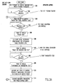
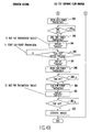
- Figures 3A and 3B and Figures 4A and 4B are, respectively, flow diagrams illustrating the logic of the separate test programs for the RF test set and the LCU. These diagrams include a sequential list of required operator actions listed with arrows pointing to the specific location in each flow diagram to which the action is related. Note that the LCU radio test software routines may either be embedded in an LCU of the first type, as specifically shown in Figures 4A and 4B, or these routines may be implemented on the PC which is used in the testing of an LCU of the second type.
- the radio test process begins in function block 301 on power-up of the test set with a prompt message displayed on the screen of the test set to press a designated key (k1) to start actual testing.
- decision block 302 the test for the k1 key press is made which, when affirmative, leads to function block 303 prompting the operator to enter the test cable insertion loss.
- decision block 304 tests for entry of the cable loss which, when affirmative, prints a "PLEASE WAIT" message to the screen in function block 305, while the test set in function block 306 configures itself to compensate for the entered insertion loss.
- test set When configured, the test set displays the "READY FOR RECEIVER BER TEST" in function block 307, and then waits in decision block 308 for the k1 key press. When k1 is pressed, the affirmative exit leads to the display of the next prompt in function block 309 "PERFORMING 8W TRANSMITTER TEST" during which the test set makes the measurements identified in function block 310 and stores the measured data in memory. In function block 311, the measured parameters are then compared to predetermined limits.
- function block 318 if all parameters are within their limits, as checked in decision block 318, the affirmative exit leads to function block 319, which displays the screen message "ALL TESTS PASSED". However, if any parameters are beyond their limits, the negative exit from decision block 318 leads to function block 320, which displays the screen massage "TEST FAILED". The program flow then proceeds to function block 321, which displays an exit selection menu prompting the operator for one of three key presses k1, k2 or k3. The three possible key presses are examined sequentially in decision blocks 322, 323 and 324.
- a k1 key press provides the affirmative answer leading to restarting the entire test; a k2 key press exists the program; or a k3 key press branches affirmatively to function block 325, which displays a prompt message again allowing a k1 or k2 key press to restart the test and also displays the measured parameters on the screen in function block 326.
- the results of the BER test are examined in decision block 331 with a fail result sounding the beeper three times in function block 332 and displaying the screen message "BER FAIL" in function block 333.
- the time out decision block 334 holds the display illuminated until a predetermined time out period elapses, at which time the display is extinguished in function block 335 and the LCU test program ends. If, however, the BER test passes, then decision block 331 is exited affirmatively which sounds the beeper one time in function block 336 and displays the screen message "BER PASS" in function block 337. At this point, the operator turns off the BER modulator resulting in the pseudorandom RF signal at the LCU radio input being removed.
- decision block 338 is no longer satisfied, and program flow proceeds to function block 339, which displays "RADIOTST”, and then waits for a "COM TEST” button press in decision block 340.
- decision block 340 is exited affirmatively resulting in the display of the "TRANSMIT” screen message in function block 341.
- a high power RF transmission is generated from the LCU radio in function block 342. This RF transmission continues until the timeout period set by decision block 343 is satisfied, resulting in the affirmative exit to function block 344 which terminates the high power RF transmission, and displays the "RADIOTST” screen message in function block 345.
- the software flow idles at decision block 346 waiting for the operator to press the "COM TEST" button again. When this button is pressed, the affirmative exit results in the display of the "TRANSMIT” scree message in function block 347, and the generation of the low power RF transmission from the LCU radio in function block 348.
Landscapes
- Engineering & Computer Science (AREA)
- Mechanical Engineering (AREA)
- Computer Networks & Wireless Communication (AREA)
- Signal Processing (AREA)
- Physics & Mathematics (AREA)
- Electromagnetism (AREA)
- Health & Medical Sciences (AREA)
- Biomedical Technology (AREA)
- General Health & Medical Sciences (AREA)
- Monitoring And Testing Of Transmission In General (AREA)
- Mobile Radio Communication Systems (AREA)
Priority Applications (1)
| Application Number | Priority Date | Filing Date | Title |
|---|---|---|---|
| EP00103323A EP1126640A1 (fr) | 2000-02-18 | 2000-02-18 | Essai sur place automatisé de radios de télémétrie de chemin de fer |
Applications Claiming Priority (1)
| Application Number | Priority Date | Filing Date | Title |
|---|---|---|---|
| EP00103323A EP1126640A1 (fr) | 2000-02-18 | 2000-02-18 | Essai sur place automatisé de radios de télémétrie de chemin de fer |
Publications (1)
| Publication Number | Publication Date |
|---|---|
| EP1126640A1 true EP1126640A1 (fr) | 2001-08-22 |
Family
ID=8167880
Family Applications (1)
| Application Number | Title | Priority Date | Filing Date |
|---|---|---|---|
| EP00103323A Withdrawn EP1126640A1 (fr) | 2000-02-18 | 2000-02-18 | Essai sur place automatisé de radios de télémétrie de chemin de fer |
Country Status (1)
| Country | Link |
|---|---|
| EP (1) | EP1126640A1 (fr) |
Cited By (8)
| Publication number | Priority date | Publication date | Assignee | Title |
|---|---|---|---|---|
| EP1661785A1 (fr) * | 2004-11-24 | 2006-05-31 | DB Regio AG | Appareil pour tester des cables de connection sur des véhicules automoteurs, de préférence sur des véhicules ferroviaires |
| US7085561B1 (en) | 2004-05-03 | 2006-08-01 | Itt Manufacturing Enterprises, Inc. | Embedded channel analysis for RF data modem |
| EP1995897A1 (fr) * | 2007-05-21 | 2008-11-26 | Research In Motion Limited | Procédé pour tester un récepteur de fréquence radio (RF) et procédés associés |
| FR2954989A1 (fr) * | 2010-01-07 | 2011-07-08 | Mobile Comfort Holding | Procede et systeme de controle a distance d'une chaine de mesure certifee |
| US8315296B2 (en) | 2007-05-21 | 2012-11-20 | Research In Motion Limited | Method for testing a radio frequency (RF) receiver and related methods |
| CN112929101A (zh) * | 2021-01-26 | 2021-06-08 | 湖南国科锐承电子科技有限公司 | 一种应用于发射机的自动测试系统及方法 |
| CN115134819A (zh) * | 2022-09-01 | 2022-09-30 | 卡斯柯信号(北京)有限公司 | 一种列控无线闭塞系统的测试方法及装置 |
| CN115996095A (zh) * | 2023-03-22 | 2023-04-21 | 天津讯联科技有限公司 | 一种自动化遥测发射机测试装置及其测试方法 |
Citations (3)
| Publication number | Priority date | Publication date | Assignee | Title |
|---|---|---|---|---|
| WO1995025390A1 (fr) * | 1994-03-16 | 1995-09-21 | Telstra Corporation Limited | Procede et appareil de mesure de parasites radioelectriques numeriques |
| EP0715424A1 (fr) * | 1994-11-30 | 1996-06-05 | Alcatel Mobile Communication Deutschland GmbH | Procédé de test d'un système radio |
| AU5258699A (en) * | 1998-10-23 | 2000-05-04 | Westinghouse Air Brake Company | Automated in situ testing of railroad telemetry radios |
-
2000
- 2000-02-18 EP EP00103323A patent/EP1126640A1/fr not_active Withdrawn
Patent Citations (3)
| Publication number | Priority date | Publication date | Assignee | Title |
|---|---|---|---|---|
| WO1995025390A1 (fr) * | 1994-03-16 | 1995-09-21 | Telstra Corporation Limited | Procede et appareil de mesure de parasites radioelectriques numeriques |
| EP0715424A1 (fr) * | 1994-11-30 | 1996-06-05 | Alcatel Mobile Communication Deutschland GmbH | Procédé de test d'un système radio |
| AU5258699A (en) * | 1998-10-23 | 2000-05-04 | Westinghouse Air Brake Company | Automated in situ testing of railroad telemetry radios |
Cited By (11)
| Publication number | Priority date | Publication date | Assignee | Title |
|---|---|---|---|---|
| US7085561B1 (en) | 2004-05-03 | 2006-08-01 | Itt Manufacturing Enterprises, Inc. | Embedded channel analysis for RF data modem |
| EP1661785A1 (fr) * | 2004-11-24 | 2006-05-31 | DB Regio AG | Appareil pour tester des cables de connection sur des véhicules automoteurs, de préférence sur des véhicules ferroviaires |
| EP1995897A1 (fr) * | 2007-05-21 | 2008-11-26 | Research In Motion Limited | Procédé pour tester un récepteur de fréquence radio (RF) et procédés associés |
| US8315296B2 (en) | 2007-05-21 | 2012-11-20 | Research In Motion Limited | Method for testing a radio frequency (RF) receiver and related methods |
| US8494040B2 (en) | 2007-05-21 | 2013-07-23 | Research In Motion Limited | Method for testing a radio frequency (RF) receiver and related methods |
| FR2954989A1 (fr) * | 2010-01-07 | 2011-07-08 | Mobile Comfort Holding | Procede et systeme de controle a distance d'une chaine de mesure certifee |
| EP2343561A1 (fr) * | 2010-01-07 | 2011-07-13 | Mobile Comfort Holding | Procédé et système de contrôle à distance d'une chaîne de mesure certifiée |
| CN112929101A (zh) * | 2021-01-26 | 2021-06-08 | 湖南国科锐承电子科技有限公司 | 一种应用于发射机的自动测试系统及方法 |
| CN112929101B (zh) * | 2021-01-26 | 2022-07-01 | 湖南国科锐承电子科技有限公司 | 一种应用于发射机的自动测试系统及方法 |
| CN115134819A (zh) * | 2022-09-01 | 2022-09-30 | 卡斯柯信号(北京)有限公司 | 一种列控无线闭塞系统的测试方法及装置 |
| CN115996095A (zh) * | 2023-03-22 | 2023-04-21 | 天津讯联科技有限公司 | 一种自动化遥测发射机测试装置及其测试方法 |
Similar Documents
| Publication | Publication Date | Title |
|---|---|---|
| US6216095B1 (en) | Automated in situ testing of railroad telemetry radios | |
| US6997418B1 (en) | Methods and apparatus for testing a train control system | |
| JP3715208B2 (ja) | 鉄道遠隔無線を試験するシステムおよびその方法 | |
| US5970438A (en) | Method and apparatus for testing rails for structural defects | |
| US8112669B2 (en) | Wireless diagnostic system | |
| US6430481B1 (en) | Remote verification of software configuration information | |
| WO2005008632A2 (fr) | Systeme embarque d'etablissement de rapports relatifs a un test officiel d'emissions | |
| EP1126640A1 (fr) | Essai sur place automatisé de radios de télémétrie de chemin de fer | |
| CN110356441B (zh) | 机车信号车载设备在车检测作业的系统、方法及装置 | |
| CN111055685A (zh) | 一种交互式模拟充电测试系统及测试方法 | |
| CN103853150A (zh) | 无线调车机车信号和监控系统车载设备的整机检测方法 | |
| CN108039918B (zh) | 一种无线便携式btm检测仪 | |
| US6873940B1 (en) | Measuring method and measuring service system using communication means | |
| KR20190124013A (ko) | 차량 자가진단 기능을 갖는 교통단말기를 이용한 차량 관제시스템 | |
| US20040122566A1 (en) | Apparatus and method for providing automated brake pipe testing | |
| MXPA99009719A (en) | Automated verification in situ of railway telemetry radios | |
| KR101035887B1 (ko) | 전자연동 장치용 카드시험기 및 그 제어방법 | |
| CN102175469A (zh) | 测试铁路车辆的至少一个设备的电子测试系统 | |
| JP2009272968A (ja) | 無線システム | |
| JP2002046554A (ja) | 車載機器管理システム | |
| CN113238105A (zh) | 机车信号车载设备检测系统及其检测装置、检测系统的安装方式和检测方法 | |
| CN202488468U (zh) | 一种铁路区间场强测试系统 | |
| CN111751569A (zh) | 车轮传感器性能检测装置、系统及方法 | |
| CN216116793U (zh) | 一种电力机车6a系统部件试验台 | |
| JP2012101581A (ja) | 列車無線システム |
Legal Events
| Date | Code | Title | Description |
|---|---|---|---|
| PUAI | Public reference made under article 153(3) epc to a published international application that has entered the european phase |
Free format text: ORIGINAL CODE: 0009012 |
|
| AK | Designated contracting states |
Kind code of ref document: A1 Designated state(s): AT BE CH CY DE DK ES FI FR GB GR IE IT LI LU MC NL PT SE |
|
| AX | Request for extension of the european patent |
Free format text: AL;LT;LV;MK;RO;SI |
|
| 17P | Request for examination filed |
Effective date: 20020214 |
|
| AKX | Designation fees paid |
Free format text: DE FR GB IT |
|
| STAA | Information on the status of an ep patent application or granted ep patent |
Free format text: STATUS: THE APPLICATION IS DEEMED TO BE WITHDRAWN |
|
| 18D | Application deemed to be withdrawn |
Effective date: 20030902 |