EP1995897A1 - Procédé pour tester un récepteur de fréquence radio (RF) et procédés associés - Google Patents
Procédé pour tester un récepteur de fréquence radio (RF) et procédés associés Download PDFInfo
- Publication number
- EP1995897A1 EP1995897A1 EP07108553A EP07108553A EP1995897A1 EP 1995897 A1 EP1995897 A1 EP 1995897A1 EP 07108553 A EP07108553 A EP 07108553A EP 07108553 A EP07108553 A EP 07108553A EP 1995897 A1 EP1995897 A1 EP 1995897A1
- Authority
- EP
- European Patent Office
- Prior art keywords
- receiver
- bit error
- ber
- estimate
- communications
- Prior art date
- Legal status (The legal status is an assumption and is not a legal conclusion. Google has not performed a legal analysis and makes no representation as to the accuracy of the status listed.)
- Withdrawn
Links
Images



Classifications
-
- H—ELECTRICITY
- H04—ELECTRIC COMMUNICATION TECHNIQUE
- H04B—TRANSMISSION
- H04B17/00—Monitoring; Testing
- H04B17/20—Monitoring; Testing of receivers
- H04B17/29—Performance testing
-
- H—ELECTRICITY
- H04—ELECTRIC COMMUNICATION TECHNIQUE
- H04B—TRANSMISSION
- H04B17/00—Monitoring; Testing
- H04B17/20—Monitoring; Testing of receivers
- H04B17/201—Monitoring; Testing of receivers for measurement of specific parameters of the receiver or components thereof
Definitions
- the present invention relates to the field of communications systems, and, more particularly, to wireless communications systems and related methods.
- Radio sensitivity measurement plays an important role in evaluating a radio frequency (RF) radio receiver's ability to detect a weak signal in either a controlled or real application environment. Radio sensitivity and receive antenna gain together determine the total isotropic sensitivity (TIS), which determines the radio downlink performance.
- RF radio frequency
- Radio sensitivity is defined as a receiving power level at the input of the radio when the bit error ratio (BER) of the radio reaches its threshold level.
- BER bit error ratio
- GSM Global System for Mobile Communications
- BER measurement accuracy and measurement time can directly affect radio sensitivity measurement accuracy and time.
- the relationship of BER and sensitivity is shown in the graph of FIG. 9 . Since BER fluctuates significantly in real sensitivity measurements, an average value of BER is typically used for estimating the sensitivity of the receiver. Yet, due to large spurious noise in the real communication environment and/or the radio itself, and sudden changes in the test environment, the average BER may even change significantly.
- a pseudo bit error ratio of a channel is determined in a receiver comprising detecting means for detecting a data sequence of a received signal, decoding means for decoding a first encoding of the detected data signal, and re-encoding means for re-encoding with the first encoding the data sequence decoded from the first encoding.
- the receiver further comprises quality determining means for providing the detected data sequence with a value for quality, and estimating means for estimating the bit error ratio-provided that the quality of the detected data sequence fulfils a predetermined quality requirement by comparing the detected data sequence with the data sequence re-encoded with first encoding.
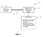
- FIG. 1 is a schematic block diagram of an exemplary test system for testing an RF receiver in accordance with one aspect.
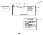
- FIG. 2 is a schematic block diagram of an alternative test system for testing an RF receiver.
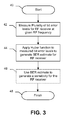
- FIG. 3 is a flow diagram of a method for testing an RF receiver in accordance with one exemplary aspect.
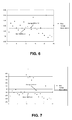
- FIGS. 4-8 are graphs of bit error levels vs. sample numbers and further illustrating average BER levels and BER levels obtained using the system and methods of FIGS. 1-3 .
- FIG. 9 is a graph of BER vs. normalized TCH level function.
- FIG. 10 is a schematic block diagram illustrating exemplary components of a mobile wireless communications device for use with the present invention.
- a method for testing a radio frequency (RF) receiver. More particularly, the method may include measuring a plurality of bit error levels for the RF receiver at a given RF frequency, and applying a Huber function to the measured plurality of bit error levels to generate a bit error ratio (BER) estimate for the RF receiver.
- BER bit error ratio
- the method may also include using the BER estimate to generate a sensitivity for the RF receiver.
- k may be within a range of about 0.8 to 1.4.
- Measuring may include measuring the plurality of bit error levels within an anechoic RF chamber.
- the measurements may be performed in an outdoor environment.
- the BER estimate may comprise a residual BER (RBER) estimate, for example.
- the RF receiver may be a Global System for Mobile Communications (GSM), General Packet Radio Service (GPRS), and/or an Enhanced Data Rates for Global System for Mobile Communications (GSM) Evolution (EDGE) receiver.
- GSM Global System for Mobile Communications
- GPRS General Packet Radio Service
- EDGE Enhanced Data Rates for Global System for Mobile Communications
- GSM Global System for Mobile Communications
- GSM Global System for Mobile Communications
- EDGE Enhanced Data Rates for Global System for Mobile Communications
- a test system for testing an RF receiver may include an RF source and a test controller coupled to the RF receiver. More particularly, the test controller may be for measuring a plurality of bit error levels for the RF receiver based upon transmissions from the RF source at a given RF frequency, and applying a Huber function to the measured plurality of bit error levels to generate a BER estimate for the RF receiver.
- the system 30 illustratively includes an RF test source 31 coupled to the receiver 32 to be tested via an RF cable 33.
- the device receiver 32 may be a Global System for Mobile Communications (GSM) receiver, a General Packet Radio Service (GPRS) receiver, and/or an Enhanced Data Rates for Global System for Mobile Communications (GSM) Evolution (EDGE) receiver, for example.
- GSM Global System for Mobile Communications
- GPRS General Packet Radio Service
- EDGE Enhanced Data Rates for Global System for Mobile Communications
- GSM Global System for Mobile Communications
- EDGE Enhanced Data Rates for Global System for Mobile Communications
- other suitable wireless receivers may also be used.
- the RF source 31 may be one of a Rohde and Schwartz universal radio communication tester CMU 200 or an Agilent 8960 base station emulator, for example, although other suitable emulators and/or RF test sources may also be used.
- a test controller 34 is connected to the device receiver 32 for performing various test operations and measurements, which will be discussed in further detail below. It should be noted that while the RF source 31 and test controller 34 are illustrated as separate components in the FIG. 1 , the functions of the RF source and test controller may in fact be performed by the same base station emulator, for example. Alternately, the test controller 34 could be a computer or computing device separate from the RF source 31, as will be appreciated by those skilled in the art.
- the test system 30' includes the RF source 31' (e.g., a base station emulator), an RF controlled enclosed environment, and the wireless handheld device receiver 32'.
- an RF controlled enclosed environment is an electromagnetic (EM) wave shield environment, such as the illustrated EM anechoic chamber 37' (which may be a full or semi-anechoic chamber), a shield room or an RF enclosure.
- An antenna 35' connected to the RF source 31' is positioned within the anechoic chamber 37' and connected to the RF source 31' by a coaxial cable to simulate a base station.
- An antenna 36' for the device receiver 32' is also positioned within the anechoic chamber 37' and connected to the receiver.
- the handheld receiver 32' and antenna 36' will be carried by a device housing, but these components may be tested without the device housing if desired.
- the open-air testing need not be performed in the anechoic chamber 37' in all embodiments. That is, these test measurements may be made in an outdoor or actual operating environment.
- test controller 32 Various method steps that may be performed by the test controller 32 will now generally be described with reference to FIG. 3 .
- wireless communications devices such as cellular devices may operate over one or more frequency bands, each of which in turn includes numerous operating frequencies or channels.
- a plurality of bit error levels are measured for the RF receiver 32, at a given one of the RF frequencies, at Block 42. Measurement of bit error levels is well within the skill of one of ordinary skill in the art using the above-described base station emulators or other tools, and therefore requires no further discussion here.
- bit error ratio (BER) estimate such as residual BER (RBER) estimate
- RBER residual BER
- the BER may then optionally be used in determining an RF receiver sensitivity of the receiver 32, at Block 46, thus concluding the illustrated method (Block 48). Further details on determining receiver sensitivity based upon BER are provided in co-pending application no. 11/364,999 , which is assigned to the present Assignee and is hereby incorporated herein in its entirety be reference.
- BER fluctuates significantly in actual sensitivity measurements, which is why an average value of BER is typically used for estimating the sensitivity of the receiver. Yet, due to large spurious noise in the real communication environment and/or the radio itself, and sudden changes in the test environment, the average BER may even change significantly.
- the traditional average used in prior art approaches is a least square (l 2 ) method, which is vulnerable to gross errors. That is, if a few spurious data points are present, this can alter the least square average significantly. In order to make this approach more robust against gross error, an l 1 method is also sometimes used. However, when the data contains many small errors, the l 1 approach can be undesirably biased towards a subset of the data points.
- a Huber function may advantageously be used in accordance with one aspect to establish a relatively smoother, less biased estimation for BER, which in turn may be used to determine radio sensitivity, as will be discussed further below.
- the solution for this minimization optimization is different from traditional optimization problems which are usually optimizing X .
- the optimization is finding the value of x * that most accurately represents the BER.
- the optimization may be performed iteratively until a minimizer is found having an absolute value less than a given threshold or delta, as will be appreciated by those skilled in the art.
- the selection of k is an important factor in finding the optimum value of x * , and may advantageously help speed up the optimization process.
- k may be in a range of about 0.8 to 1.4, although other values may be used in different embodiments.
- x i ⁇ x * m , i 1 , 2 , ... , l ⁇ , where x *( m ) is the x * value of m iteration.
- the above-described approach is relatively robust against gross errors, as well as being relatively stable against small biased data. This approach may also lead to a more robust sensitivity determination, as well as help to speed up the measurement process. Moreover, using the above-described selection process for determining k, this may result in the exclusion of potentially noisy points. Further, the use of a closed form equation may also contribute to fast convergence optimization, as will be appreciated by those skilled in the art.
- bit error level data sets illustrated in FIGS. 4 and 5 demonstrate the difference between a traditional average method vs. the Huber approach set forth above without noise and when spurious data points are present in the data set (i.e., with noise), respectively. Sample sets of twenty-five measurements were used in both FIGS. 4 and 5 .
- spurious data was caused by opening the door of a shielded test box, which would not ordinarily be done during a typical test measurement, but is provided here to show how the two approaches can significantly differ in real world scenarios where noise is present.
- the above-described Huber approach provides a BER that is close to the standard average BER in FIG. 4 without spurious data (i.e., 1.38 for Huber BER vs. 1.32 for average BER).
- the Huber BER is significantly more accurate than the standard average (i.e., 1.53 vs. 1.75).
- FIGS. 6 and 7 real world data sets taken outside (i.e., not in an anechoic chamber) are shown (both of which also include twenty-five sample points) for moderate and severe noise conditions, respectively.
- the Huber BER was 2.44 and more accurate than the comparable average BER of 2.50 for the moderate noise environment ( FIG. 6 ).
- the Huber BER was significantly more accurate, i.e., 2.82 compared to 3.46 for the average BER.
- Huber approach Another potential advantage of the Huber approach is that it can in some instances provide more accurate results than the standard average approach even with less data points.
- FIG. 8 One such example is illustrated in FIG. 8 , in which the Huber BER was determined using twenty-five of a total forty data points. As can be seen, the average with no noise using all forty data points was 1.4, and the average with noise using all forty data points was 1.75. Yet, the Huber BER with noise and only twenty-five data points was 1.53. Accordingly, the Huber BER approach may advantageously be used in certain embodiments with less samples, which reduces data sampling time and speeds up the measurements.
- the device 1000 illustratively includes a housing 1200, a keypad 1400 and an output device 1600.
- the output device shown is a display 1600, which is preferably a full graphic LCD. Other types of output devices may alternatively be utilized.
- a processing device 1800 is contained within the housing 1200 and is coupled between the keypad 1400 and the display 1600. The processing device 1800 controls the operation of the display 1600, as well as the overall operation of the mobile device 1000, in response to actuation of keys on the keypad 1400 by the user.
- the housing 1200 may be elongated vertically, or may take on other sizes and shapes (including clamshell housing structures).
- the keypad may include a mode selection key, or other hardware or software for switching between text entry and telephony entry.
- FIG. 10 In addition to the processing device 1800, other parts of the mobile device 1000 are shown schematically in FIG. 10 . These include a communications subsystem 1001; a short-range communications subsystem 1020; the keypad 1400 and the display 1600, along with other input/output devices 1060, 1080, 1100 and 1120; as well as memory devices 1160, 1180 and various other device subsystems 1201.
- the mobile device 1000 is preferably a two-way RF communications device having voice and data communications capabilities.
- the mobile device 1000 preferably has the capability to communicate with other computer systems via the Internet.
- Operating system software executed by the processing device 1800 is preferably stored in a persistent store, such as the flash memory 1160, but may be stored in other types of memory devices, such as a read only memory (ROM) or similar storage element.
- system software, specific device applications, or parts thereof may be temporarily loaded into a volatile store, such as the random access memory (RAM) 1180. Communications signals received by the mobile device may also be stored in the RAM 1180.
- the processing device 1800 in addition to its operating system functions, enables execution of software applications 1300A-1300N on the device 1000.
- a predetermined set of applications that control basic device operations, such as data and voice communications 1300A and 1300B, may be installed on the device 1000 during manufacture.
- a personal information manager (PIM) application may be installed during manufacture.
- the PIM is preferably capable of organizing and managing data items, such as e-mail, calendar events, voice mails, appointments, and task items.
- the PIM application is also preferably capable of sending and receiving data items via a wireless network 1401.
- the PIM data items are seamlessly integrated, synchronized and updated via the wireless network 1401 with the device user's corresponding data items stored or associated with a host computer system.
- the communications subsystem 1001 includes a receiver 1500, a transmitter 1520, and one or more antennas 1540 and 1560.
- the communications subsystem 1001 also includes a processing module, such as a digital signal processor (DSP) 1580, and local oscillators (LOs) 1601.
- DSP digital signal processor
- LOs local oscillators
- a mobile device 1000 may include a communications subsystem 1001 designed to operate with the Mobitex TM , Data TAC TM or General Packet Radio Service (GPRS) mobile data communications networks, and also designed to operate with any of a variety of voice communications networks, such as AMPS, TDMA, CDMA, WCDMA, PCS, GSM, EDGE, etc. Other types of data and voice networks, both separate and integrated, may also be utilized with the mobile device 1000.
- the mobile device 1000 may also be compliant with other communications standards such as 3GSM, 3GPP, UMTS, etc.
- Network access requirements vary depending upon the type of communication system. For example, in the Mobitex and DataTAC networks, mobile devices are registered on the network using a unique personal identification number or PIN associated with each device. In GPRS networks, however, network access is associated with a subscriber or user of a device. A GPRS device therefore requires a subscriber identity module, commonly referred to as a SIM card, in order to operate on a GPRS network.
- SIM card subscriber identity module
- the mobile device 1000 may send and receive communications signals over the communication network 1401.
- Signals received from the communications network 1401 by the antenna 1540 are routed to the receiver 1500, which provides for signal amplification, frequency down conversion, filtering, channel selection, etc., and may also provide analog to digital conversion. Analog-to-digital conversion of the received signal allows the DSP 1580 to perform more complex communications functions, such as demodulation and decoding.
- signals to be transmitted to the network 1401 are processed (e.g. modulated and encoded) by the DSP 1580 and are then provided to the transmitter 1520 for digital to analog conversion, frequency up conversion, filtering, amplification and transmission to the communication network 1401 (or networks) via the antenna 1560.
- the DSP 1580 provides for control of the receiver 1500 and the transmitter 1520. For example, gains applied to communications signals in the receiver 1500 and transmitter 1520 may be adaptively controlled through automatic gain control algorithms implemented in the DSP 1580.
- a received signal such as a text message or web page download
- the communications subsystem 1001 is input to the processing device 1800.
- the received signal is then further processed by the processing device 1800 for an output to the display 1600, or alternatively to some other auxiliary I/O device 1060.
- a device user may also compose data items, such as e-mail messages, using the keypad 1400 and/or some other auxiliary I/O device 1060, such as a touchpad, a rocker switch, a thumb-wheel, or some other type of input device.
- the composed data items may then be transmitted over the communications network 1401 via the communications subsystem 1001.
- a voice communications mode In a voice communications mode, overall operation of the device is substantially similar to the data communications mode, except that received signals are output to a speaker 1100, and signals for transmission are generated by a microphone 1120.
- Alternative voice or audio I/O subsystems such as a voice message recording subsystem, may also be implemented on the device 1000.
- the display 1600 may also be utilized in voice communications mode, for example to display the identity of a calling party, the duration of a voice call, or other voice call related information.
- the short-range communications subsystem enables communication between the mobile device 1000 and other proximate systems or devices, which need not necessarily be similar devices.
- the short-range communications subsystem may include an infrared device and associated circuits and components, or a Bluetooth TM communications module to provide for communication with similarly-enabled systems and devices.
Landscapes
- Physics & Mathematics (AREA)
- Electromagnetism (AREA)
- Engineering & Computer Science (AREA)
- Computer Networks & Wireless Communication (AREA)
- Signal Processing (AREA)
- Mobile Radio Communication Systems (AREA)
- Monitoring And Testing Of Transmission In General (AREA)
- Detection And Prevention Of Errors In Transmission (AREA)
Priority Applications (2)
| Application Number | Priority Date | Filing Date | Title |
|---|---|---|---|
| EP07108553A EP1995897A1 (fr) | 2007-05-21 | 2007-05-21 | Procédé pour tester un récepteur de fréquence radio (RF) et procédés associés |
| CA2629325A CA2629325C (fr) | 2007-05-21 | 2008-05-20 | Methode d'essai de recepteur a radio frequence et methodes associees |
Applications Claiming Priority (1)
| Application Number | Priority Date | Filing Date | Title |
|---|---|---|---|
| EP07108553A EP1995897A1 (fr) | 2007-05-21 | 2007-05-21 | Procédé pour tester un récepteur de fréquence radio (RF) et procédés associés |
Publications (1)
| Publication Number | Publication Date |
|---|---|
| EP1995897A1 true EP1995897A1 (fr) | 2008-11-26 |
Family
ID=38510430
Family Applications (1)
| Application Number | Title | Priority Date | Filing Date |
|---|---|---|---|
| EP07108553A Withdrawn EP1995897A1 (fr) | 2007-05-21 | 2007-05-21 | Procédé pour tester un récepteur de fréquence radio (RF) et procédés associés |
Country Status (2)
| Country | Link |
|---|---|
| EP (1) | EP1995897A1 (fr) |
| CA (1) | CA2629325C (fr) |
Cited By (1)
| Publication number | Priority date | Publication date | Assignee | Title |
|---|---|---|---|---|
| CN112040439A (zh) * | 2020-07-27 | 2020-12-04 | 深圳市金溢科技股份有限公司 | Obu射频参数的校准方法、obu设备、射频设备及系统 |
Families Citing this family (1)
| Publication number | Priority date | Publication date | Assignee | Title |
|---|---|---|---|---|
| CN102547803A (zh) * | 2012-01-30 | 2012-07-04 | 中兴通讯股份有限公司 | 一种基站的射频测试系统、方法及多工器 |
Citations (2)
| Publication number | Priority date | Publication date | Assignee | Title |
|---|---|---|---|---|
| US5691988A (en) * | 1994-11-17 | 1997-11-25 | Hewlett-Packard Company | Method for measuring the sensitivities and interference wave properties fo receivers |
| EP1126640A1 (fr) * | 2000-02-18 | 2001-08-22 | Westinghouse Air Brake Company | Essai sur place automatisé de radios de télémétrie de chemin de fer |
-
2007
- 2007-05-21 EP EP07108553A patent/EP1995897A1/fr not_active Withdrawn
-
2008
- 2008-05-20 CA CA2629325A patent/CA2629325C/fr not_active Expired - Fee Related
Patent Citations (2)
| Publication number | Priority date | Publication date | Assignee | Title |
|---|---|---|---|---|
| US5691988A (en) * | 1994-11-17 | 1997-11-25 | Hewlett-Packard Company | Method for measuring the sensitivities and interference wave properties fo receivers |
| EP1126640A1 (fr) * | 2000-02-18 | 2001-08-22 | Westinghouse Air Brake Company | Essai sur place automatisé de radios de télémétrie de chemin de fer |
Cited By (2)
| Publication number | Priority date | Publication date | Assignee | Title |
|---|---|---|---|---|
| CN112040439A (zh) * | 2020-07-27 | 2020-12-04 | 深圳市金溢科技股份有限公司 | Obu射频参数的校准方法、obu设备、射频设备及系统 |
| CN112040439B (zh) * | 2020-07-27 | 2024-05-31 | 深圳市金溢科技股份有限公司 | Obu射频参数的校准方法、obu设备、射频设备及系统 |
Also Published As
| Publication number | Publication date |
|---|---|
| CA2629325A1 (fr) | 2008-07-29 |
| CA2629325C (fr) | 2010-07-06 |
Similar Documents
| Publication | Publication Date | Title |
|---|---|---|
| US8494040B2 (en) | Method for testing a radio frequency (RF) receiver and related methods | |
| KR101136671B1 (ko) | 무선 디바이스의 방사 성능을 결정하기 위한 방법 및 장치 | |
| CN101034945B (zh) | 确定总全向灵敏度(tis)的系统和有关方法 | |
| EP2003800B1 (fr) | Système pour déterminer la sensibilité isotrope totale (TIS) utilisant la valeur d'indicateur de force de signal reçu cible (RSSI) et procédés associés | |
| US7773964B2 (en) | Systems, methods and apparatus for determining a radiated performance of a wireless device | |
| US9762335B2 (en) | Assessing aircraft interference path loss employing discrete frequency stirring | |
| CN101034946B (zh) | 确定辐射的射频(rf)接收机灵敏度的系统和有关方法 | |
| US8489032B2 (en) | System and method for sensitivity measurement in wireless mobile stations | |
| JP4429330B2 (ja) | Rf発生源とrf受信機との間のrf経路損失を決定するシステムおよびその関連方法 | |
| CA2629325C (fr) | Methode d'essai de recepteur a radio frequence et methodes associees | |
| EP3503438A1 (fr) | Agencement et procédé d'essai | |
| US11451312B2 (en) | Mobile-assisted phase calibration method and system | |
| CN108307421B (zh) | 无线终端的测量方法、计算机可读存储介质、装置及系统 | |
| Cammin et al. | Employing correlation for wireless components and device characterization in reverberation chambers | |
| Hubrechsen et al. | NB-IoT devices in reverberation chambers: A comprehensive uncertainty analysis | |
| JP4356753B2 (ja) | Rf発生源とヒステリシスを有するrf受信機との間のrf経路損失を決定するシステムおよびその関連方法 | |
| Chen et al. | Novel Nakagami-m parameter estimator for noisy channel samples | |
| Kvarnstrand et al. | Comparison on Convergence of Measurements in Reverberation Chamber for Different Channel Bandwidths | |
| KR100646117B1 (ko) | 미세발진 검출 방법 및 장치, 그 장치를 구비한 와이브로중계기 | |
| CN101018094B (zh) | 确定传导的射频(rf)接收机灵敏度的系统和有关方法 | |
| EP4455689A1 (fr) | Élimination d'interférence d'intermodulation d'équipement de test et de bruit de mesures de densité spectrale de puissance | |
| Walker | Choosing the Right Programmable Attenuator for Receiver Sensitivity Tests. | |
| Selvan | A revisit of the reference antenna gain measurement method | |
| Auinger et al. | Validation of the Decomposition Method for Fast MIMO Over‐the‐Air Measurements | |
| Bosch | Numerical Analysis of the Decomposition Method Using LTE Reference Antennas |
Legal Events
| Date | Code | Title | Description |
|---|---|---|---|
| PUAI | Public reference made under article 153(3) epc to a published international application that has entered the european phase |
Free format text: ORIGINAL CODE: 0009012 |
|
| 17P | Request for examination filed |
Effective date: 20070521 |
|
| AK | Designated contracting states |
Kind code of ref document: A1 Designated state(s): AT BE BG CH CY CZ DE DK EE ES FI FR GB GR HU IE IS IT LI LT LU LV MC MT NL PL PT RO SE SI SK TR |
|
| AX | Request for extension of the european patent |
Extension state: AL BA HR MK RS |
|
| AKX | Designation fees paid |
Designated state(s): AT BE BG CH CY CZ DE DK EE ES FI FR GB GR HU IE IS IT LI LT LU LV MC MT NL PL PT RO SE SI SK TR |
|
| 17Q | First examination report despatched |
Effective date: 20090813 |
|
| RAP1 | Party data changed (applicant data changed or rights of an application transferred) |
Owner name: BLACKBERRY LIMITED |
|
| RAP1 | Party data changed (applicant data changed or rights of an application transferred) |
Owner name: BLACKBERRY LIMITED |
|
| GRAP | Despatch of communication of intention to grant a patent |
Free format text: ORIGINAL CODE: EPIDOSNIGR1 |
|
| RIC1 | Information provided on ipc code assigned before grant |
Ipc: H04B 17/20 20150101AFI20160922BHEP Ipc: H04B 17/29 20150101ALI20160922BHEP |
|
| INTG | Intention to grant announced |
Effective date: 20161012 |
|
| STAA | Information on the status of an ep patent application or granted ep patent |
Free format text: STATUS: THE APPLICATION IS DEEMED TO BE WITHDRAWN |
|
| 18D | Application deemed to be withdrawn |
Effective date: 20170223 |