EP1126936B1 - Vorrichtung zum entfernen von walzgutbunden aus einer entsprechenden wickelmaschine - Google Patents
Vorrichtung zum entfernen von walzgutbunden aus einer entsprechenden wickelmaschine Download PDFInfo
- Publication number
- EP1126936B1 EP1126936B1 EP99949297A EP99949297A EP1126936B1 EP 1126936 B1 EP1126936 B1 EP 1126936B1 EP 99949297 A EP99949297 A EP 99949297A EP 99949297 A EP99949297 A EP 99949297A EP 1126936 B1 EP1126936 B1 EP 1126936B1
- Authority
- EP
- European Patent Office
- Prior art keywords
- coil
- supporting frame
- rotation
- trolley
- axis
- Prior art date
- Legal status (The legal status is an assumption and is not a legal conclusion. Google has not performed a legal analysis and makes no representation as to the accuracy of the status listed.)
- Expired - Lifetime
Links
Images

Classifications
-
- B—PERFORMING OPERATIONS; TRANSPORTING
- B21—MECHANICAL METAL-WORKING WITHOUT ESSENTIALLY REMOVING MATERIAL; PUNCHING METAL
- B21C—MANUFACTURE OF METAL SHEETS, WIRE, RODS, TUBES, PROFILES OR LIKE SEMI-MANUFACTURED PRODUCTS OTHERWISE THAN BY ROLLING; AUXILIARY OPERATIONS USED IN CONNECTION WITH METAL-WORKING WITHOUT ESSENTIALLY REMOVING MATERIAL
- B21C47/00—Winding-up, coiling or winding-off metal wire, metal band or other flexible metal material characterised by features relevant to metal processing only
- B21C47/24—Transferring coils to or from winding apparatus or to or from operative position therein; Preventing uncoiling during transfer
Definitions
- This invention concerns a device to remove coils of rolled stock from a corresponding coiling machine, as set forth in the main claim.
- the device is suitable to remove coils of rolled stock such as bars, plate, or rods (smooth or ribbed) of hot-rolled metal material, with a cross-section either round, square, rectangular, hexagonal or otherwise.
- the device according to the invention is placed downstream of a traditional rolling train, provided with a precision coiling machine, that is to say, of the type wherein the individual spirals are formed under the guidance of mechanical means which regulate their packing, density and tension.
- the state of the art covers a device to remove coils of rolled stock associated with a rolling train wherein each coil of rolled stock, coiled by a coiling machine on a vertical axis, is removed by a first trolley which, keeping the coil vertical, lifts it and carries it to a second trolley used to transport and convey the coil.
- This device has the disadvantage that it cannot be used to remove and move coils formed on coiling machines with a horizontal axis of rotation, since it has no means suitable to perform this movement.
- DE-A-34 04 893 which forms the basis for the preamble of claim 1, discloses an apparatus for removing and setting down a coil of rolled strip wound around an expanding mandrel, wherein pincer arms surround the cylindrical outer circumference of the ring of the rolled strip, carry pressure rollers and are controlled by an actuator mounted in a supporting frame that can be moved above and parallel to the axis of the expanding mandrel.
- the pincer arms have the shape of two half rings, are pivoted on pivots of the supporting frame, and are connected to one another by an intermediate joint, which is connected to the actuator by means of a connecting lever.
- This apparatus is only useful to allow the formation of the coil within the space defined by the two pincer arms and to move the formed coil up and down, and along a direction parallel to the axis of the expanding mandrel.
- US-A-5,544,828 discloses an automatic bobbin changing device for a winding machine with a vertical winding axis, wherein the device comprises a bobbin carrier which can rotate about a vertical axis and which can adopt two bobbin-holding positions staggered at an angle of about 180°.
- the bobbin carrier has four gripper arms which work together in pair to grip a bobbin.
- On each gripper arm is a horizontal bobbin-support surface which, during the bobbin-changing operation, is positioned under the bobbin lower-flange.
- the bobbin is changed by lifting the bobbin carrier by means of a lifting mechanism, in such a way that the bobbin on the winding machine is lifted off its mounting; the bobbin carrier is subsequently rotated through 180° and then lowered again.
- each bobbin remains always in a vertical position and the bobbin-support surface are only provided to temporarily lift each bobbin from its mounting element.
- each bobbin-support surface is a part the corresponding gripper arm and is not selectively movable with respect thereto.
- US-A-5,332,351 discloses a coil unloading and transport apparatus having means for rotating the coil from a horizontal storage shaft to a pallet for further transport.
- the finished coil is pushed horizontally by a pushing device of the rewinder away from the storage shaft towards a receiving shaft of the movable carriage.
- the device to remove coils of rolled stock from a corresponding coiling machine according to the invention is set forth and characterised in the main claim, while the dependent claims describe other characteristics of the invention.
- the main purpose of the invention is to achieve a device to remove coils of rolled stock wherein the coil formed in the coiling machine can be removed without unravelling the spirals and without damaging the outer layers, and wherein it is possible to transport the coil to a tying station first and to a weighing and storing station later both quickly and safely.
- the device comprises means to remove the coil, which are associated with the coiling machine and are movable, in a direction substantially parallel to the axis of rotation thereof, between a first inactive position, wherein they are arranged outside the space occupied by the coiling machine itself, and a first working position, wherein they cooperate with the coil of rolled stock to remove it and move it.
- Actuation means are also provided to move the removal means from the inactive position to the first working position and vice versa.
- a second purpose of the invention is to achieve a device to remove and move coils of rolled stock wherein each coil is maintained compact during the removal and movement steps.
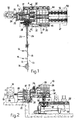
- a device 10 according to the invention is arranged next to a coiling machine 11, to remove and move coils of rolled stock 12 coiled by the latter.
- the coiling machine 11 is located downstream of a hot rolling train 13 suitable to produce rolled stock 12 such as bars, plate, or rods (smooth or ribbed) of metal material, with a cross-section either round, square, rectangular, hexagonal or otherwise.
- the rolling train 13 can be of any known type, comprising drawing rollers 14, a loop-forming device 15 and a shears 16 suitable to shear to size the rolled stock 12 to be coiled.
- the looper 15 is suitable to regulate the flow of rolled stock 12 towards the coiling machine 11 and to make it correctly perform the increase in diameter step, during the same coiling operation.
- the looper 15 thus fulfils a function of a buffer for the rolled stock 12 before it is coiled.
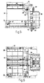
- the coiling machine 11 is of the precision type, that is to say, the type wherein the individual spirals are formed under the guidance of mechanical means which regulate the packing, the density and the tension; it comprises a mandrel or reel 17 with a horizontal axis of rotation 19 (Fig. 3), mounted cantilevered and rotatable on a vertical turret 20 of a stationary metallic structure 21, driven by an electric motor 18.
- a cylindrical containing plate 22 is suitable to cooperate with the outer end of the mandrel 17; the cylindrical plate 22 is mounted rotatable and cantilevered on one end of an arm 23, the other end of which pivots on the stationary structure 21.
- the cylindrical plate 22 can move between a working position (Fig. 2), wherein it is arranged substantially orthogonal to the axis of rotation 19 of the mandrel 17 and cooperating therewith, and an inactive position, or position wherein the coil is removed (Fig. 3), wherein it is arranged substantially horizontal, distanced from the mandrel 17 and lowered with respect thereto.
- the mandrel 17 is formed by four retractable elements, movable radially so as to facilitate the removal of the just-formed coil of rolled stock 12.
- the radial movement of the four elements is obtained with a hydraulically commanded and water cooled mechanism 24.
- a device to distribute the spirals 25 comprising a tubular guide 26, about 5.5 metres long and with one end 28 movable both horizontally and vertically.
- tubular guide 26 lies on a plane substantially horizontal and tangent to the outer cylindrical surface of the mandrel 17.
- the device 10 also comprises a trolley 30 provided with wheels 31 (Fig. 4-6) sliding on fixed rails 32, arranged parallel to the axis of rotation 19 and commanded by an actuator 33 of a hydraulic type.
- a supporting frame 36 pivots on transverse pins 35 of the trolley 30; in turn, four levers 37 pivot on the supporting frame 36 and are arranged substantially at 90° with respect to each other; at the end of each of the four levers 37 a corresponding idler roller 38 is mounted rotatable.
- the four rollers 38 have their axes of rotation parallel to each other, and are suitable to cooperate with the trailing end of the rolled stock 12 to prevent the spirals from unravelling and to keep the coil compact.
- the four levers 37 are commanded by corresponding hydraulic actuators 39 to displace the rollers 38 radially.
- Two fork-type levers 41 pivot on the frame 36 and are suitable to be actuated by corresponding hydraulic actuators 42.
- Two hydraulic actuators 44 and 45 mounted on the upper part of the trolley 30, are suitable to command the rotation by 90° of the supporting frame 36 between a first working position (Fig. 2) wherein the axes of the rollers 38 are horizontal and parallel to the axis of rotation 19 of the mandrel 17, so as to execute the step of gripping and removing the coil of rolled stock, and a second working position (Fig. 3) wherein the axes of the rollers 38 are substantially vertical, so as to execute the step of releasing each coil of rolled stock 12 formed on the coiling machine 11, after the coil has been overturned through 90°.
- the device 10 also comprises an assembly 47 to transport the coils which comprises a bench 49 movable vertically and commanded hydraulically.
- the bench 49 is provided with four movable grippers 50, also commanded hydraulically, which are suitable to grip the coil supported by the fork-type levers 41 of the frame 36, with the axis in the vertical position, to prevent the coil from unravelling, and hold it until it reaches the tying step.
- the coil transport assembly 47 also comprises a tying and strapping station 51, wherein the coils of rolled stock 12 are tied in a known manner.
- the bench 49 is also able to rotate on itself through 90°, together with the coil which it is carrying, so that the tying station 51, although it has only two tying machines, one opposite the other, is able to perform at least four tying operations for each coil.
- the coil transport assembly 47 also comprises a chain transporter 52, provided with a weighing bascule 53 to weigh the coils.
- the transporter 52 is suitable to discharge and store the coils of rolled stock 12 formed on the coiling machine 11.
- the device 10 as described heretofore functions as follows:
- the trolley 30 In the inactive position the trolley 30 is outside the space occupied by the coiling machine 11, which is prepared to receive the rolled stock 12 to be coiled. To be more exact, the cylindrical plate 22 is positioned in contact with the outer end of the mandrel 17 (Fig. 2).
- the mandrel 17 and with it the cylindrical plate 22 is made to rotate by the motor 18.
- the rolled stock 12 arriving from the rolling train 13 (Fig. 1) is drawn by the drawing rollers 14 at a very high speed, more than 40 metres per second, towards the coiling machine 11 and the device 25 to distribute the spirals guides the leading end of the rolled stock 12 towards the mandrel 17.
- rollers 14 of the looper 15 guarantee that the rolled stock 12 is kept under tension and that it is coiled under traction onto the mandrel 17 of the coiling machine 11. They also form the loop needed to accumulate rolled stock 12 to be supplied quickly to the coiling machine 11 as the diameters of the coil are increased during the same coiling cycle.
- the drawing rollers 14 brake the trailing end of the rolled stock 12, to keep it at the desired tension when the mandrel 17 decelerates and stops at the end of the coiling step.
- the rolled stock 12 is then guided by the tubular guide 26 which is displaced horizontally, backwards and forwards and upwards, at the end of every ring of spirals. It is thus possible to obtain a rational and controlled distribution of the spirals both on every single ring and also on the different coaxial rings which form the coil.
- the coil is formed until the rolled stock 12 has been completely coiled.
- the shears 16 is commanded to shear to size the rolled stock 12 which is coiling on the coiling machine 11, in such a way that the dimensions and weight of the coil are predefined.
- the actuators 39 are actuated so that the rollers 38 close on the still-rotating coil and thus prevent the last spirals of the coil from unravelling. In this way the rollers 53 also collaborate in the final step of coiling the trailing end of the coil, and thus maintain the coil compact.
- the actuators 42 are actuated to take the fork-type levers 41 to be inserted between the coil and the vertical turret 20, both to remove the coil and also to ensure that the coil is supported while it is removed and rotated by 90°.
- the trolley 30 is then translated horizontally towards its starting position (Fig. 2) so that the coil is removed horizontally from the mandrel 17, which at the same time retracts radially to facilitate the removal of the coil.
- the actuators 43 and 45 are then actuated to make the support 36 rotate by 90°, together with the coil which is attached thereto, in such a way as to take the coil itself above the bench 49 which is already prepared in a raised position.
- the grippers 50 grip the coil of rolled stock 12 to prevent it from unravelling.
- the bench 49 is made to descend and is displaced towards the tying and strapping station 51 where the coil is tied.
- the chain transporter 53 then provides to transport the coil towards the weighing bascule 56 and subsequently to a storage zone where it may be moved further.
Landscapes
- Engineering & Computer Science (AREA)
- Mechanical Engineering (AREA)
- Winding, Rewinding, Material Storage Devices (AREA)
- Control And Other Processes For Unpacking Of Materials (AREA)
- Replacement Of Web Rolls (AREA)
Claims (6)
- Vorrichtung zum Entfernen von Walzgutringen (12) aus einer Wickelmaschine (11), die nach einer Walzstraße (13) angeordnet ist und einen Aufspanndorn (17) aufweist, der um eine in einer im wesentlichen horizontalen Ebene liegende Drehachse (19) drehbar ist, wobei die Vorrichtung einen Wagen (30) besitzt, der an festen Leitelementen (32) parallel zur Drehachse (19) des Aufspanndornes (17) gleitbar ist, wobei ferner ein Tragrahmen (36) an diesem Wagen (30) angeordnet ist und eine Mehrzahl von Rollen (38) auf diesem Tragrahmen (36) angeordnet sind, deren Drehachsen im wesentlichen parallel zur Drehachse (19) des Aufspanndornes (17) liegen und die mit dem Ring zusammenwirken um zu verhindern, daß die Windungen des Walzgutes (12) sich abwickeln, der Wagen (30) und der darauf montierte Tragrahmen (36) sind in einer Richtung beweglich, die im wesentlichen parallel zur Drehachse (19) des Aufspanndornes (17) liegt, und zwar zwischen einer nicht aktiven Stellung, in der der Wagen (30) und der Tragrahmen (36) außerhalb des durch die Wickelmaschine (11) eingenommenen Raumes sich befinden, und einer Arbeitsstellung, bei der die Rollen (38) mit den von der Wickelmaschine (11) gebildeten Walzgutringen (12) zusammenwirken, ferner sind erste Betädgungsmittel (33) vorgesehen, die zur Bewegung des Wagens (30) und des Tragrahmens (36) zwischen der inaktiven Stellung und der Arbeitsstellung und umgekehrt dienen, dadurch gekennzeichnet, daß der Tragrahmen (36) am Wagen (33) drehbar angeordnet ist, und zwar für eine Drehung zwischen einer ersten axialen Stellung im wesentlichen parallel zur Drehachse (19) und einer zweiten axialen Stellung im wesentlichen senkrecht auf diese Drehachse (19), ferner daß zweite Betätigungsmittel (44, 45) vorgesehen sind, um den Tragrahmen (36) zwischen der ersten axialen Stellung und der zweiten axialen Stellung zu drehen und die Drehung der Spulenachse um etwa 90° zu bewirken, und daß weiter der Tragrahmen (36) eine Reihe von Traghebeln (41) aufweist, die an dem Tragrahmen (36) montiert sind, wobei die Traghebel (41) quer zum Walzgutring (12) bewegbar sind, um mit diesem Ring zusammenzuwirken, die axiale Abnahme des Ringes vom Aufspanndorn (17) durchzuführen, wenn der Wagen (30) und der Tragrahmen (36) in die Arbeitsstellung bewegt werden sind, sowie den Ring während der Drehung um etwa 90° zu tragen.
- Vorrichtung nach Anspruch 1, dadurch gekennzeichnet, daß die Traghebel (41) am Tragrahmen (36) schwenkbar angeordnet sind und daß dritte Betätigungsmittel (42) vorgesehen sind, um die Schwenkung der Traghebel (41) zwischen einer zurückgezogenen Stellung im Abstand von dem Ring, und einer aktiven Stellung durchzuführen, in der die Traghebel (41) mit dem Ring zusammenwirken.
- Vorrichtung nach Anspruch 1, bei der die Drehachse (19) des Aufspanndomes (17) in einer im wesentlichen horizontalen Ebene liegt, dadurch gekennzeichnet, daß dem Wagen (30) eine Transportanordnung (47) zugeordnet ist, um den horizontalen Transport des Ringes zu einer Bindestation (51) zu ermöglichen.
- Vorrichtung nach Anspruch 3, dadurch gekennzeichnet, daß die Transporteinheit (47) einen vertikal bewegbaren Arbeitstisch (49) aufweist, der mit einer Mehrzahl von bewegbaren Greifein (50) für das Greifen des von den Traghebeln (41) getragenen Ringes aufweist, wobei die Achse des Ringes in einer vertikalen Stellung ist um ein Aufspulen des Ringes zu verhindern.
- Vorrichtung nach Anspruch 4, dadurch gekennzeichnet, daß dieser Arbeitstisch (49) mit dem Ring, den er trägt, drehbar ist, sodaß die Bindestation (51) mindestens zwei Bindeoperationen für jede der Windungen mit der gleichen Bindemaschine durchführen kann.
- Vorrichtung nach Anspruch 1, dadurch gekennzeichnet, daß Hebemittel (53) nach dem Wagen (30) und dem Tiagrahmen (36) angeordnet sind, um den Ring zu heben und zu wägen.
Applications Claiming Priority (3)
| Application Number | Priority Date | Filing Date | Title |
|---|---|---|---|
| IT1998UD000188A IT1302792B1 (it) | 1998-11-04 | 1998-11-04 | Dispositivo per estrarre e movimentare matasse di prodottilaminati avvolte da una corrispondente rocchettatrice |
| ITDA980188U | 1998-11-04 | ||
| PCT/IB1999/001760 WO2000025953A1 (en) | 1998-11-04 | 1999-11-01 | Device to remove coils of rolled stock from a corresponding coiling machine |
Publications (2)
| Publication Number | Publication Date |
|---|---|
| EP1126936A1 EP1126936A1 (de) | 2001-08-29 |
| EP1126936B1 true EP1126936B1 (de) | 2003-03-26 |
Family
ID=11422772
Family Applications (1)
| Application Number | Title | Priority Date | Filing Date |
|---|---|---|---|
| EP99949297A Expired - Lifetime EP1126936B1 (de) | 1998-11-04 | 1999-11-01 | Vorrichtung zum entfernen von walzgutbunden aus einer entsprechenden wickelmaschine |
Country Status (6)
| Country | Link |
|---|---|
| US (1) | US6354197B1 (de) |
| EP (1) | EP1126936B1 (de) |
| AU (1) | AU6225899A (de) |
| ES (1) | ES2192401T3 (de) |
| IT (1) | IT1302792B1 (de) |
| WO (1) | WO2000025953A1 (de) |
Families Citing this family (3)
| Publication number | Priority date | Publication date | Assignee | Title |
|---|---|---|---|---|
| KR100798069B1 (ko) * | 2001-11-21 | 2008-01-28 | 주식회사 포스코 | 코일 자동 포장장치 |
| US7004718B2 (en) * | 2002-12-24 | 2006-02-28 | Braner Harold R | Downender transport table |
| CN106240890B (zh) * | 2016-08-31 | 2018-08-21 | 中山市索尼格自动化机械设备有限公司 | 一种线圈捆扎方法及实施该方法的全自动线圈捆扎设备 |
Family Cites Families (13)
| Publication number | Priority date | Publication date | Assignee | Title |
|---|---|---|---|---|
| US3123236A (en) * | 1964-03-03 | Apparatus for transferring coils of metallic strip | ||
| US2336614A (en) * | 1942-03-26 | 1943-12-14 | American Steel & Wire Co | Rod bundle transfer device |
| US2776764A (en) * | 1953-09-21 | 1957-01-08 | Gerrard & Co A J | Apparatus for handling coil strip material |
| US3139024A (en) * | 1962-07-24 | 1964-06-30 | Allegheny Ludlum Steel | Coil handling apparatus |
| BE759942A (fr) * | 1969-12-08 | 1971-05-17 | Morgan Construction Co | Dispositif pour transferer des bobines de produit cylindrique d'un poste de formation de bobines a un transporteur adjacent |
| FR2429150A1 (fr) * | 1979-02-22 | 1980-01-18 | Mecanarbed Sa | Machine pour lier les bobines de fil metallique |
| JPS59141317A (ja) * | 1983-02-02 | 1984-08-14 | Kawasaki Steel Corp | コイル抜き取り方法およびその装置 |
| JPS6044471A (ja) * | 1983-08-19 | 1985-03-09 | Hitachi Cable Ltd | 舞輪取り装置 |
| DE3404893A1 (de) * | 1984-02-11 | 1985-08-14 | SMS Schloemann-Siemag AG, 4000 Düsseldorf | Vorrichtung zum abnehmen und absetzen von auf einen spreizdorn gehaspelten walzbandringen |
| DE3543692A1 (de) * | 1985-12-11 | 1987-06-19 | Breyell Metall | Verfahren und einrichtung zum abbinden von bandringen |
| IT1238986B (it) * | 1990-01-31 | 1993-09-17 | Impianti Ind | Sistema automatizzato di confezione ed evacuazione rotoli di filo metallico avvolti su bobine |
| US5332351A (en) * | 1991-06-25 | 1994-07-26 | Nelson Jacqueline S | Coil unloading and transportation apparatus and method |
| DE4136545B4 (de) * | 1991-11-06 | 2004-05-19 | Maschinenfabrik Niehoff Gmbh & Co Kg | Spulenwechselvorrichtung |
-
1998
- 1998-11-04 IT IT1998UD000188A patent/IT1302792B1/it active IP Right Grant
-
1999
- 1999-11-01 ES ES99949297T patent/ES2192401T3/es not_active Expired - Lifetime
- 1999-11-01 AU AU62258/99A patent/AU6225899A/en not_active Abandoned
- 1999-11-01 WO PCT/IB1999/001760 patent/WO2000025953A1/en not_active Ceased
- 1999-11-01 EP EP99949297A patent/EP1126936B1/de not_active Expired - Lifetime
- 1999-11-02 US US09/432,151 patent/US6354197B1/en not_active Expired - Fee Related
Also Published As
| Publication number | Publication date |
|---|---|
| AU6225899A (en) | 2000-05-22 |
| ES2192401T3 (es) | 2003-10-01 |
| ITUD980188A1 (it) | 2000-05-04 |
| EP1126936A1 (de) | 2001-08-29 |
| US6354197B1 (en) | 2002-03-12 |
| WO2000025953A1 (en) | 2000-05-11 |
| IT1302792B1 (it) | 2000-09-29 |
Similar Documents
| Publication | Publication Date | Title |
|---|---|---|
| US6318660B1 (en) | Coiling machine for rolled stock | |
| RU2507019C1 (ru) | Держатель для рулона металла и устройства, снабженные таким держателем | |
| EP0943569A2 (de) | Wickelmaschine | |
| JP2002541041A (ja) | 巻き取り心棒と巻き戻し機械用の巻芯を準備する方法及び装置 | |
| CN100384557C (zh) | 用于轧材的卷绕装置 | |
| EP1126933B1 (de) | Wickelanlage für walzgut | |
| EP1126936B1 (de) | Vorrichtung zum entfernen von walzgutbunden aus einer entsprechenden wickelmaschine | |
| CA2303119A1 (en) | High speed transfer of strip in a continuous strip processing application | |
| JPS6034677Y2 (ja) | ウエブ巻取機用ロ−ル取り替え装置 | |
| EP0444311B2 (de) | Automatisiertes System zum Verpacken und Entfernen von auf Haspeln gewickelten Metalldrahtrollen | |
| US3827274A (en) | Strand drawing apparatus including means for preparing the leading end of the strand | |
| EP4429834B1 (de) | Anlage und verfahren zum abwickeln von drahtspulen | |
| US4768364A (en) | Continuous coiling machine for rod and strip stock | |
| US3536274A (en) | Strand drawing and handling system | |
| CN100522407C (zh) | 轧制设备和用于制造金属带的方法 | |
| EP1706225B1 (de) | Wickelvorrichtung und -verfahren für gewalzte oder gezogene lange produkte | |
| EP3109192B1 (de) | Wickler zum wickeln einer faserbahn | |
| EP1706226B1 (de) | Wickelverfahren und -vorrichtung für gewalzte oder gezogene lange produkte | |
| DE69906352T2 (de) | Vorrichtung zum entfernen von walzgutbunden aus einer entsprechenden wickelmaschine | |
| US4941625A (en) | Creel for the simultaneous changing of reels of metallic wire | |
| EP3527517A1 (de) | Wickler zum wickeln einer faserbahn | |
| JPH05246587A (ja) | 広幅帯状シート用スリッターリワインダー | |
| CN119018717A (zh) | 一种缆索自动化搬运设备及其使用方法 | |
| CN121241007A (zh) | 具有包括可扩张引导辊的结绳组件的拉伸缠绕机 | |
| JPH0629101B2 (ja) | シ−トロ−ル取外し装置付きシ−ト分割巻取機 |
Legal Events
| Date | Code | Title | Description |
|---|---|---|---|
| PUAI | Public reference made under article 153(3) epc to a published international application that has entered the european phase |
Free format text: ORIGINAL CODE: 0009012 |
|
| 17P | Request for examination filed |
Effective date: 20010529 |
|
| AK | Designated contracting states |
Kind code of ref document: A1 Designated state(s): AT BE CH CY DE DK ES FI FR GB GR IE IT LI LU MC NL PT SE |
|
| GRAG | Despatch of communication of intention to grant |
Free format text: ORIGINAL CODE: EPIDOS AGRA |
|
| 17Q | First examination report despatched |
Effective date: 20020516 |
|
| GRAG | Despatch of communication of intention to grant |
Free format text: ORIGINAL CODE: EPIDOS AGRA |
|
| GRAH | Despatch of communication of intention to grant a patent |
Free format text: ORIGINAL CODE: EPIDOS IGRA |
|
| GRAH | Despatch of communication of intention to grant a patent |
Free format text: ORIGINAL CODE: EPIDOS IGRA |
|
| GRAA | (expected) grant |
Free format text: ORIGINAL CODE: 0009210 |
|
| AK | Designated contracting states |
Designated state(s): AT BE CH CY DE DK ES FI FR GB GR IE IT LI LU MC NL PT SE |
|
| PG25 | Lapsed in a contracting state [announced via postgrant information from national office to epo] |
Ref country code: NL Free format text: LAPSE BECAUSE OF FAILURE TO SUBMIT A TRANSLATION OF THE DESCRIPTION OR TO PAY THE FEE WITHIN THE PRESCRIBED TIME-LIMIT Effective date: 20030326 Ref country code: LI Free format text: LAPSE BECAUSE OF FAILURE TO SUBMIT A TRANSLATION OF THE DESCRIPTION OR TO PAY THE FEE WITHIN THE PRESCRIBED TIME-LIMIT Effective date: 20030326 Ref country code: GR Free format text: LAPSE BECAUSE OF FAILURE TO SUBMIT A TRANSLATION OF THE DESCRIPTION OR TO PAY THE FEE WITHIN THE PRESCRIBED TIME-LIMIT Effective date: 20030326 Ref country code: FI Free format text: LAPSE BECAUSE OF FAILURE TO SUBMIT A TRANSLATION OF THE DESCRIPTION OR TO PAY THE FEE WITHIN THE PRESCRIBED TIME-LIMIT Effective date: 20030326 Ref country code: CH Free format text: LAPSE BECAUSE OF FAILURE TO SUBMIT A TRANSLATION OF THE DESCRIPTION OR TO PAY THE FEE WITHIN THE PRESCRIBED TIME-LIMIT Effective date: 20030326 Ref country code: BE Free format text: LAPSE BECAUSE OF FAILURE TO SUBMIT A TRANSLATION OF THE DESCRIPTION OR TO PAY THE FEE WITHIN THE PRESCRIBED TIME-LIMIT Effective date: 20030326 |
|
| REG | Reference to a national code |
Ref country code: GB Ref legal event code: FG4D |
|
| REG | Reference to a national code |
Ref country code: CH Ref legal event code: EP |
|
| REF | Corresponds to: |
Ref document number: 69906352 Country of ref document: DE Date of ref document: 20030430 Kind code of ref document: P |
|
| REG | Reference to a national code |
Ref country code: IE Ref legal event code: FG4D |
|
| PG25 | Lapsed in a contracting state [announced via postgrant information from national office to epo] |
Ref country code: SE Free format text: LAPSE BECAUSE OF FAILURE TO SUBMIT A TRANSLATION OF THE DESCRIPTION OR TO PAY THE FEE WITHIN THE PRESCRIBED TIME-LIMIT Effective date: 20030626 Ref country code: PT Free format text: LAPSE BECAUSE OF FAILURE TO SUBMIT A TRANSLATION OF THE DESCRIPTION OR TO PAY THE FEE WITHIN THE PRESCRIBED TIME-LIMIT Effective date: 20030626 Ref country code: DK Free format text: LAPSE BECAUSE OF FAILURE TO SUBMIT A TRANSLATION OF THE DESCRIPTION OR TO PAY THE FEE WITHIN THE PRESCRIBED TIME-LIMIT Effective date: 20030626 |
|
| NLV1 | Nl: lapsed or annulled due to failure to fulfill the requirements of art. 29p and 29m of the patents act | ||
| ET | Fr: translation filed | ||
| REG | Reference to a national code |
Ref country code: ES Ref legal event code: FG2A Ref document number: 2192401 Country of ref document: ES Kind code of ref document: T3 |
|
| REG | Reference to a national code |
Ref country code: CH Ref legal event code: PL |
|
| PG25 | Lapsed in a contracting state [announced via postgrant information from national office to epo] |
Ref country code: LU Free format text: LAPSE BECAUSE OF NON-PAYMENT OF DUE FEES Effective date: 20031101 Ref country code: CY Free format text: LAPSE BECAUSE OF FAILURE TO SUBMIT A TRANSLATION OF THE DESCRIPTION OR TO PAY THE FEE WITHIN THE PRESCRIBED TIME-LIMIT Effective date: 20031101 |
|
| PG25 | Lapsed in a contracting state [announced via postgrant information from national office to epo] |
Ref country code: IE Free format text: LAPSE BECAUSE OF NON-PAYMENT OF DUE FEES Effective date: 20031103 |
|
| PG25 | Lapsed in a contracting state [announced via postgrant information from national office to epo] |
Ref country code: MC Free format text: LAPSE BECAUSE OF NON-PAYMENT OF DUE FEES Effective date: 20031130 |
|
| PLBE | No opposition filed within time limit |
Free format text: ORIGINAL CODE: 0009261 |
|
| STAA | Information on the status of an ep patent application or granted ep patent |
Free format text: STATUS: NO OPPOSITION FILED WITHIN TIME LIMIT |
|
| 26N | No opposition filed |
Effective date: 20031230 |
|
| REG | Reference to a national code |
Ref country code: IE Ref legal event code: MM4A |
|
| PGFP | Annual fee paid to national office [announced via postgrant information from national office to epo] |
Ref country code: GB Payment date: 20121025 Year of fee payment: 14 |
|
| PGFP | Annual fee paid to national office [announced via postgrant information from national office to epo] |
Ref country code: FR Payment date: 20130107 Year of fee payment: 14 Ref country code: AT Payment date: 20121024 Year of fee payment: 14 |
|
| REG | Reference to a national code |
Ref country code: AT Ref legal event code: MM01 Ref document number: 235329 Country of ref document: AT Kind code of ref document: T Effective date: 20131101 |
|
| GBPC | Gb: european patent ceased through non-payment of renewal fee |
Effective date: 20131101 |
|
| REG | Reference to a national code |
Ref country code: FR Ref legal event code: ST Effective date: 20140731 |
|
| PG25 | Lapsed in a contracting state [announced via postgrant information from national office to epo] |
Ref country code: AT Free format text: LAPSE BECAUSE OF NON-PAYMENT OF DUE FEES Effective date: 20131101 |
|
| PG25 | Lapsed in a contracting state [announced via postgrant information from national office to epo] |
Ref country code: GB Free format text: LAPSE BECAUSE OF NON-PAYMENT OF DUE FEES Effective date: 20131101 Ref country code: FR Free format text: LAPSE BECAUSE OF NON-PAYMENT OF DUE FEES Effective date: 20131202 |
|
| PGFP | Annual fee paid to national office [announced via postgrant information from national office to epo] |
Ref country code: DE Payment date: 20151022 Year of fee payment: 17 |
|
| PGFP | Annual fee paid to national office [announced via postgrant information from national office to epo] |
Ref country code: ES Payment date: 20151106 Year of fee payment: 17 |
|
| REG | Reference to a national code |
Ref country code: DE Ref legal event code: R119 Ref document number: 69906352 Country of ref document: DE |
|
| PG25 | Lapsed in a contracting state [announced via postgrant information from national office to epo] |
Ref country code: DE Free format text: LAPSE BECAUSE OF NON-PAYMENT OF DUE FEES Effective date: 20170601 |
|
| PG25 | Lapsed in a contracting state [announced via postgrant information from national office to epo] |
Ref country code: ES Free format text: LAPSE BECAUSE OF FAILURE TO SUBMIT A TRANSLATION OF THE DESCRIPTION OR TO PAY THE FEE WITHIN THE PRESCRIBED TIME-LIMIT Effective date: 20030326 |
|
| REG | Reference to a national code |
Ref country code: ES Ref legal event code: FD2A Effective date: 20181119 |
|
| RIC2 | Information provided on ipc code assigned after grant |
Ipc: B21C 47/24 20060101AFI20000515BHEP Ipc: B65H 67/04 20060101ALI20000515BHEP Ipc: B21C 47/00 20060101ALI20000515BHEP |
|
| PG25 | Lapsed in a contracting state [announced via postgrant information from national office to epo] |
Ref country code: ES Free format text: LAPSE BECAUSE OF FAILURE TO SUBMIT A TRANSLATION OF THE DESCRIPTION OR TO PAY THE FEE WITHIN THE PRESCRIBED TIME-LIMIT Effective date: 20161102 |
|
| PGFP | Annual fee paid to national office [announced via postgrant information from national office to epo] |
Ref country code: IT Payment date: 20181023 Year of fee payment: 20 |