EP1127004B1 - Methode und vorrichtung zur bestimmung des gierwinkels eines satelliten - Google Patents
Methode und vorrichtung zur bestimmung des gierwinkels eines satelliten Download PDFInfo
- Publication number
- EP1127004B1 EP1127004B1 EP99971773A EP99971773A EP1127004B1 EP 1127004 B1 EP1127004 B1 EP 1127004B1 EP 99971773 A EP99971773 A EP 99971773A EP 99971773 A EP99971773 A EP 99971773A EP 1127004 B1 EP1127004 B1 EP 1127004B1
- Authority
- EP
- European Patent Office
- Prior art keywords
- satellite
- angle
- yaw
- axis
- pitch
- Prior art date
- Legal status (The legal status is an assumption and is not a legal conclusion. Google has not performed a legal analysis and makes no representation as to the accuracy of the status listed.)
- Expired - Lifetime
Links
- 238000000034 method Methods 0.000 title claims description 48
- 238000005259 measurement Methods 0.000 claims description 44
- 230000008878 coupling Effects 0.000 description 5
- 238000010168 coupling process Methods 0.000 description 5
- 238000005859 coupling reaction Methods 0.000 description 5
- 238000013480 data collection Methods 0.000 description 5
- 238000012544 monitoring process Methods 0.000 description 5
- 230000007613 environmental effect Effects 0.000 description 4
- 230000000694 effects Effects 0.000 description 3
- 230000007812 deficiency Effects 0.000 description 2
- 238000011161 development Methods 0.000 description 2
- 230000018109 developmental process Effects 0.000 description 2
- 230000032683 aging Effects 0.000 description 1
- 238000013459 approach Methods 0.000 description 1
- 230000000712 assembly Effects 0.000 description 1
- 238000000429 assembly Methods 0.000 description 1
- 230000015556 catabolic process Effects 0.000 description 1
- 238000012937 correction Methods 0.000 description 1
- 230000001351 cycling effect Effects 0.000 description 1
- 238000006731 degradation reaction Methods 0.000 description 1
- 230000001934 delay Effects 0.000 description 1
- 238000001514 detection method Methods 0.000 description 1
- 230000010354 integration Effects 0.000 description 1
- 230000003287 optical effect Effects 0.000 description 1
- 238000012545 processing Methods 0.000 description 1
- 238000011084 recovery Methods 0.000 description 1
- 238000005070 sampling Methods 0.000 description 1
- 238000009987 spinning Methods 0.000 description 1
- 230000003068 static effect Effects 0.000 description 1
- 238000006467 substitution reaction Methods 0.000 description 1
- 230000036561 sun exposure Effects 0.000 description 1
- 230000001052 transient effect Effects 0.000 description 1
Images

Classifications
-
- G—PHYSICS
- G01—MEASURING; TESTING
- G01C—MEASURING DISTANCES, LEVELS OR BEARINGS; SURVEYING; NAVIGATION; GYROSCOPIC INSTRUMENTS; PHOTOGRAMMETRY OR VIDEOGRAMMETRY
- G01C21/00—Navigation; Navigational instruments not provided for in groups G01C1/00 - G01C19/00
- G01C21/24—Navigation; Navigational instruments not provided for in groups G01C1/00 - G01C19/00 specially adapted for cosmonautical navigation
-
- B—PERFORMING OPERATIONS; TRANSPORTING
- B64—AIRCRAFT; AVIATION; COSMONAUTICS
- B64G—COSMONAUTICS; VEHICLES OR EQUIPMENT THEREFOR
- B64G1/00—Cosmonautic vehicles
- B64G1/22—Parts of, or equipment specially adapted for fitting in or to, cosmonautic vehicles
- B64G1/24—Guiding or controlling apparatus, e.g. for attitude control
- B64G1/244—Spacecraft control systems
-
- B—PERFORMING OPERATIONS; TRANSPORTING
- B64—AIRCRAFT; AVIATION; COSMONAUTICS
- B64G—COSMONAUTICS; VEHICLES OR EQUIPMENT THEREFOR
- B64G1/00—Cosmonautic vehicles
- B64G1/22—Parts of, or equipment specially adapted for fitting in or to, cosmonautic vehicles
- B64G1/24—Guiding or controlling apparatus, e.g. for attitude control
- B64G1/244—Spacecraft control systems
- B64G1/245—Attitude control algorithms for spacecraft attitude control
-
- B—PERFORMING OPERATIONS; TRANSPORTING
- B64—AIRCRAFT; AVIATION; COSMONAUTICS
- B64G—COSMONAUTICS; VEHICLES OR EQUIPMENT THEREFOR
- B64G1/00—Cosmonautic vehicles
- B64G1/22—Parts of, or equipment specially adapted for fitting in or to, cosmonautic vehicles
- B64G1/24—Guiding or controlling apparatus, e.g. for attitude control
- B64G1/28—Guiding or controlling apparatus, e.g. for attitude control using inertia or gyro effect
- B64G1/285—Guiding or controlling apparatus, e.g. for attitude control using inertia or gyro effect using momentum wheels
-
- B—PERFORMING OPERATIONS; TRANSPORTING
- B64—AIRCRAFT; AVIATION; COSMONAUTICS
- B64G—COSMONAUTICS; VEHICLES OR EQUIPMENT THEREFOR
- B64G1/00—Cosmonautic vehicles
- B64G1/22—Parts of, or equipment specially adapted for fitting in or to, cosmonautic vehicles
- B64G1/24—Guiding or controlling apparatus, e.g. for attitude control
- B64G1/36—Guiding or controlling apparatus, e.g. for attitude control using sensors, e.g. sun-sensors, horizon sensors
- B64G1/365—Guiding or controlling apparatus, e.g. for attitude control using sensors, e.g. sun-sensors, horizon sensors using horizon or Earth sensors
-
- B—PERFORMING OPERATIONS; TRANSPORTING
- B64—AIRCRAFT; AVIATION; COSMONAUTICS
- B64G—COSMONAUTICS; VEHICLES OR EQUIPMENT THEREFOR
- B64G1/00—Cosmonautic vehicles
- B64G1/22—Parts of, or equipment specially adapted for fitting in or to, cosmonautic vehicles
- B64G1/24—Guiding or controlling apparatus, e.g. for attitude control
- B64G1/36—Guiding or controlling apparatus, e.g. for attitude control using sensors, e.g. sun-sensors, horizon sensors
- B64G1/369—Guiding or controlling apparatus, e.g. for attitude control using sensors, e.g. sun-sensors, horizon sensors using gyroscopes as attitude sensors
Definitions
- the invention relates to a method and an apparatus for determining the yaw angle of a satellite.
- the exact orientation of the satellite has to be known.
- the roll angle, the pitch angle and the yaw angle which will described in greater detail further below, have to be measured or estimated.
- Most geostationary, so called “three-axis stabilized" satellites are provided with sensors that allow to measure and actively control the roll and pitch angle. In this case, no sensor is provided for measuring the yaw angle.
- the yaw angle is usually estimated and controlled by means of the roll/yaw coupling that occurs throughout the orbit when an angular momentum bias is present on the spacecraft, for instance when a momentum wheel is spinning inside. Since this coupling is actually very light, a proper yaw angle estimation and correction takes several hours.
- US-A-5 556 058 discloses a method for determining the yaw angle of a satellite, wherein the yaw angle is calculated by means of at least two angle sensors and wherein the calculation is calibrated by means of a sun sensor.
- a problem of the method according to US-A-5 556 058 arises from the fact that the sun passes out of the field of view of the sun sensor once each orbit. For this reason, the method according to US-A-5 556 058 has to provide two modes of operation corresponding to whether or not the sun is in the field of view of the sun sensor.
- the invention according to the claims 1 and 9 performs the calibration on a sample yaw angle which has been determined on the basis of the angle sensors.
- the invention according to the claims 5 and 13 performs a calibration on each single angle value which has been determined on the basis of the angle sensors and determines thereafter the calibrated value of a yaw angle.
- a very advantageous aspect of the invention is the fact that the invention needs no estimation schemes which introduce a considerable delay in computing the yaw angle. Rather the invention makes use of a direct measurement of the yaw angle by means of sensors already present on the satellite. This makes is possible to provide a fast yaw measurement avoiding to collect hours of data before be able to infer a good yaw estimation.
- the method is not based on a model matching estimation scheme as mentioned hereabove, but on a direct measurement of the yaw angle purely based on the geometry of the sensors. In other words, this method does not require long data collection periods, but only needs one measurement on two sensors to infer a yaw angle. This is particularly of interest when the spacecraft undergoes some unexpected attitude disturbance. In this case, if a model-matching estimation scheme is used, since the model would not fit the observation, the whole data collection should be restarted after the disturbance for proper yaw estimation. With the method according to the invention, only one measurement, at some point in time, of two offset sensors would be needed before, during or after the disturbance to infer a valid yaw measurement. Furthermore, this method does not suffer any observability problem. Hence, the method is fast and reliable and is perfectly suited for real time or historical monitoring of yaw pointing.
- Another important aspect of the invention is to monitor the performances of all different subsystems of a satellite for supervision and error recovery.
- the ground station can infer the yaw angle profile over the same time span. This is done by applying some numerical estimation scheme to the roll angle data, using a numerical model of the spacecraft's dynamics and kinematics. For instance, a least square fitting can be worked out in that workframe. These estimation methods are based on the adjustment of the model's parameters to match the way the roll profile has varied over the period of observation. However, not only these methods require long observation durations for accurate yaw estimation, due to low coupling between roll and yaw, they also require very good modeling of the environmental disturbance torques for proper modeling of the spacecraft dynamics.
- the spacecraft only disposes of a roll angle and a pitch angle measurement device, the constant term of the fourier series of the yaw environmental torque is not distinguishable from the yaw angle itself. Therefore, in this case, the yaw is not estimated as such, but the estimation outputs the sum of the yaw angle and the influence of the constant term of the yaw environmental torque. In this configuration, it is impossible to verify the magnitude of the parasitical effect of the torque's constant term. If this effect is large, it will significantly bias the whole yaw estimation.
- the method according to the invention can be implemented in real time and allows the operator not only to verify the magnitude of the yaw angle at some point in time, but also to track the profile of the yaw angle throughout hours, days or years. It for instance allows comparisons of daily yaw profiles to make sure there is no attitude control performance degradation or unexpected variation in yaw angle. It could also be looked at if there is any clue of yaw transient (e.g. poor broadcasting).
- a further aspect of the present invention deals with the calibration of the yaw angle measurement which is performed as mentioned above.
- the method according to the invention allows to measure the yaw angle from the reading of two different sensors measuring the roll and/or pitch angles, provided that the reference point of the two sensors are not identical.
- the description is given basically for geostationary satellites but the invention can be applied directly to satellites which are stationary with respect to any star.
- the method can also be employed for non circular orbits. The method assumes that the orbit of the spacecraft is known at any time.
- the location of the center of the frame (orbit) is less involved in the following development. It should be noted that in any case the orbit only affects the location of the reference points of the sensors on earth. So if the orbit is not geostationary, the location of the reference points on the earth deterministically vary throughout this orbit.
- the three axes are named roll, pitch and yaw and are oriented as shown in fig. 1, i.e.
- the orientation of the satellite can be specified in terms of rotations about these three axes so that one may speak of roll, pitch and yaw angles.
- Roll, pitch and yaw angles are actually "Euler angles". This means that they represent the orientation of a body with respect to a reference orientation by consecutive rotations around the corresponding axes.
- the final orientation depends on the order of rotations. In other words, if the yaw/pitch/roll order of rotations is picked, then starting from the reference frame of Fig. 1, the final attitude is reached by first rotating the frame around the yaw axis, then rotating the frame around the new pitch axis, then around the new roll axis.
- the final orientation would not be the same if the rotations were performed, with the same magnitude, but in a different order. However, if the magnitude of the rotations are small enough, the final attitude becomes almost independent of the order of rotations. This approximation is often applied when the attitude errors of a properly controlled geostationary satellite are considered, since its pointing errors are very small.
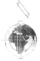
- Fig. 2 shows the earth seen from a satellite, as well as the directions P and R in which pitch and roll errors will move a beam sent by the satellite on the earth.
- the solid lines show the directions along which roll and pitch errors would be measured if there were no yaw error, the dotted lines give the same information but when some positive yaw error is present.
- points G and N locate distinct reference points of two sensors provided on-board the satellite.
- the reference point of each sensor is defined as the location it points to when the errors it reads are zero.
- two sensors used on-board the ASTRA satellites are considered in the following, but different kinds of sensors may be used as well.
- One sensor is an optical infrared earth sensor assembly (ESA) with the subnadir point N (center of the earth) as its reference point.
- the other sensor is a beacon sensor with the ground station G as its reference point.
- ESA optical infrared earth sensor assembly
- Each sensor issues roll and pitch angle attitude errors defining the difference between the direction it points to, its "boresight", and its reference point (identified by points G and N).
- the satellite transmits the telemetry values of the measured roll and pitch angles of both sensors to the ground station which records them for further processing and/or analysis.
- the roll and pitch errors of at least one of the sensors are also sent to the on-board processor for roll and pitch control.
- the method explained below extends to any kind of pair of sensors measuring roll and pitch angles or two linear combination of these angles, as long as the reference points G and N of the two sensors are different.
- the method can also readily be extended to a point N not being on the center of the earth.
- Delta_p and Delta_r are small angles. This slightly simplifies the considerations below. This assumption has been verified for all ASTRA spacecrafts since a yaw angle of the order of a degree leads to Delta_p and Delta_r which are about one tenth thereof.
- pitch_G and roll_G are actually the azimuth and elevation of the ground station (Betzdorf, Germany) as seen from the spacecraft, while since Delta_p and Delta_r are small the angles pitch_GP and roll_GP can be defined as follows:
- equation (13) is often enough to determine the yaw angle and its sign. Therefore, most of the time, only one equation is sufficient. However, equation (8) and (14) can provide additional information to refine the yaw angle.
- the yaw angle as measured this way has already been shown to fit the integration of yaw gyro rates, for instance. It will be an invaluable source of attitude information, especially in cases where the knowledge of the yaw angle becomes critical.
- the above described method is based on measurement values from two sensors as mostly used in geostationary satellites, for example the ASTRA satellites.
- the principle of the invention can also be used even if measurement values of only two single sensors, for example two single roll sensors or two single pitch sensors are available since two independent equations exist.
- all variables, except « yaw » and « roll_GP » are known.
- only the pitch angle is measured.
- the location of G is still known in roll and pitch.
- the yaw angle can be determined with two offset sensors, each one reading only one attitude angle, as long as the reference point of each sensor is known. It should be noted that this method determines « yaw » and « roll_GP » or « pitch_GP » the latter ones being deduced from delta angles between the two sensor readings and not representing the real roll or pitch angle. Therefore, if the roll and pitch angles are needed for control, this method cannot determine them in addition to the yaw angle, but at least one of the sensors has to measure both roll and pitch. However, as demonstrated here above, in this particular case, both roll and pitch angles do not have to be measured to determine the yaw angle.
- spurious sensor errors are constant errors (alignment errors) and one orbit varying (daily for geostationary spacecrafts).
- the method In order to get rid of the constant and of the daily variation, the method must be calibrated.
- a quiet orbit is needed, which means a full orbit revolution without attitude disturbance and without station keeping moves, without unusual external disturbances and without unusual activity affecting the satellite's attitude.
- the quiet orbit according to the invention is used as a reference orbit.
- the output of all angle sensors are then used for yaw measurement and are collected over the reference orbit which is 24 hours of data collection for geostationary satellites.
- a yaw profile is computed from the collected data.
- Yaw is measured with the method according to the invention with the collected data over the quiet orbit. Note that sampling time can be adjusted to match typical rate of variation of the yaw angle.
- the yaw angle is computed at the desired time as explained above.
- the yaw computed at the same orbit location on the reference orbit is then subtracted from this computed yaw and the result gives the calibrated yaw angle.
- This calibration method reduces the measuring of the yaw relative to the yaw that was measured at the same point on the reference orbit. It assumes that the yaw profile observed on the reference orbit was a real yaw pointing offset and variation.
- a sensor profile is recorded for each angle sensor on the satellite.
- This calibration consists of again picking a quiet orbit and recording necessary roll or pitch data to compute yaw on this orbit. Then, at the time yaw measure is desired, the ground station measures the set of roll or pitch data required to compute yaw. Then, deduct roll or pitch data collected at the same location on the reference orbit from respective roll or pitch data at the time yaw measurement is desired. Then, compute yaw based on calibrated set of roll or pitch data.
- This calibration method assumes that the yaw remained equal to zero throughout the reference orbit. It assumes that the yaw that would have been computed with the sensor errors on this reference orbit would only have been due to spurious errors on the sensors, like the ones coming from thermal distortion or alignment errors.
Landscapes
- Engineering & Computer Science (AREA)
- Remote Sensing (AREA)
- Radar, Positioning & Navigation (AREA)
- Chemical & Material Sciences (AREA)
- Aviation & Aerospace Engineering (AREA)
- Combustion & Propulsion (AREA)
- Automation & Control Theory (AREA)
- Physics & Mathematics (AREA)
- Life Sciences & Earth Sciences (AREA)
- General Life Sciences & Earth Sciences (AREA)
- Geochemistry & Mineralogy (AREA)
- Geology (AREA)
- Environmental & Geological Engineering (AREA)
- Astronomy & Astrophysics (AREA)
- General Physics & Mathematics (AREA)
- Navigation (AREA)
- Control Of Position, Course, Altitude, Or Attitude Of Moving Bodies (AREA)
Claims (16)
- Verfahren zur Bestimmung eines kalibrierten Werts eines Gierwinkels eines Satelliten,
wobei ein festes kartesisches Koordinatensystem in Bezug auf den Satelliten definiert ist, mit einer ersten Achse, die im Wesentlichen tangential zur Umlaufbahn des Satelliten gerichtet ist und einen Rollwinkel definiert, mit einer zweiten Achse, die im Wesentlichen senkrecht zur Umlaufbahnebene des Satelliten gerichtet ist und einen Nickwinkel definiert, und mit einer dritten Achse, die im Wesentlichen radial zur Umlaufbahn des Satelliten gerichtet ist und einen Gierwinkel definiert,
mit den folgenden Schritten:wobei der Abtastwert des Gierwinkels zur Kalibrierungszeit (t0) durch folgende Schritte bestimmt wird:Bereitstellung von mindestens zwei Winkelsensoren mit Messachsen, die anti-parallel zu der dritten Achse sind und verschiedene Referenzpunkte haben (G, N),Speicherung eines Gierwinkelprofils über einer ungestörten Umlaufbahn,Bestimmung eines Abtastwerts des Gierwinkels zu einer Kalibrierungszeit (t0) undBestimmung des kalibrierten Werts eines Gierwinkels, indem von dem Abtastwert des Gierwinkels der Wert des Gierwinkelprofils bei einem Zeitversatz abgezogen wird, der der Kalibrierungszeit (t0) entspricht,Messung der Winkel um die Messachsen der mindestens zwei Winkelsensoren,Bestimmung des Abtastwerts des Gierwinkels auf der Basis der gemessenen Winkel. - Verfahren nach Anspruch 1, wobei eine Messachse der ersten Achse entspricht.
- Verfahren nach einem der Ansprüche 1 - 2, wobei eine Messachse der zweiten Achse entspricht.
- Verfahren nach einem der Ansprüche 1 - 3, wobei der Satellit ein geostationärer Satellit ist.
- Verfahren zur Bestimmung eines kalibrierten Werts eines Gierwinkels eines Satelliten,
wobei ein festes kartesisches Koordinatensystem in Bezug auf den Satelliten definiert ist, mit einer ersten Achse, die im Wesentlichen tangential zur Umlaufbahn des Satelliten gerichtet ist und einen Rollwinkel definiert, mit einer zweiten Achse, die im Wesentlichen senkrecht zur Umlaufbahnebene des Satelliten gerichtet ist und einen Nickwinkel definiert und mit einer dritten Achse, die im Wesentlichen radial zur Umlaufbahn des Satelliten gerichtet ist und einen Gierwinkel definiert,
mit den folgenden Schritten:Bereitstellung von mindestens zwei Winkelsensoren mit Messachsen, die anti-parallel zu der dritten Achse sind und verschiedene Referenzpunkte haben (G, N),Speicherung eines Profils für jeden Winkelsensor über einer ungestörten Umlaufbahn,Messung der Winkel um die Messachsen der mindestens zwei Winkelsensoren zu einer Kalibrierungszeit (t0),Bestimmung von kalibrierten Werten der mindestens zwei gemessenen Winkel, indem von den mindestens zwei gemessenen Winkeln die Werte des Profils des jeweiligen Winkelsensors bei einem Zeitversatz abgezogen werden, der der Kalibrierungszeit (t0) entspricht,Bestimmung des kalibrierten Werts eines Gierwinkels auf der Basis der kalibrierten Werte der mindestens zwei gemessenen Winkel. - Verfahren nach Anspruch 5, wobei eine Messachse der ersten Achse entspricht.
- Verfahren nach einem der Ansprüche 5 - 6, wobei eine Messachse der zweiten Achse entspricht.
- Verfahren nach einem der Ansprüche 5 - 7, wobei der Satellit ein geostationärer Satellit ist.
- Gerät zur Bestimmung eines kalibrierten Werts eines Gierwinkels eines Satelliten,
wobei ein festes kartesisches Koordinatensystem in Bezug auf den Satelliten definiert ist, mit einer ersten Achse, die im Wesentlichen tangential zur Umlaufbahn des Satelliten gerichtet ist und einen Rollwinkel definiert, mit einer zweiten Achse, die im Wesentlichen senkrecht zur Umlaufbahnebene des Satelliten gerichtet ist und einen Nickwinkel definiert und mit einer dritten Achse, die im Wesentlichen radial zur Umlaufbahn des Satelliten gerichtet ist und einen Gierwinkel definiert,
das beinhaltet:wobei die Maßnahmen zur Bestimmung des Abtastwerts des Gierwinkels des Weiteren folgendes beinhaltet:mindestens zwei Winkelsensoren mit Messachsen, die anti-parallel zu der dritten Achse sind und verschiedene Referenzpunkte haben (G, N),Maßnahmen zur Speicherung eines Gierwinkelprofils über einer ungestörten Umlaufbahn,Maßnahmen zur Bestimmung eines Abtastwerts des Gierwinkels zu einer Kalibrierungszeit (t0), undMaßnahmen zur Bestimmung des kalibrierten Werts eines Gierwinkels, indem von dem Abtastwert des Gierwinkels der Wert des Gierwinkelprofils bei einem Zeitversatz abgezogen wird, der der Kalibrierungszeit (t0) entspricht,Maßnahmen zur Messung der Winkel um die Messachsen der mindestens zwei Winkelsensoren,Maßnahmen zur Bestimmung des Abtastwerts des Gierwinkels auf der Basis der gemessenen Winkel. - Gerät nach Anspruch 9, wobei eine Messachse der ersten Achse entspricht.
- Gerät nach einem der Ansprüche 9 - 10, wobei eine Messachse der zweiten Achse entspricht.
- Gerät nach einem der Ansprüche 9 - 11, wobei der Satellit ein geostationärer Satellit ist.
- Gerät zur Bestimmung eines kalibrierten Werts eines Gierwinkels eines Satelliten,
wobei ein festes kartesisches Koordinatensystem in Bezug auf den Satelliten definiert ist, mit einer ersten Achse, die im Wesentlichen tangential zur Umlaufbahn des Satelliten gerichtet ist und einen Rollwinkel definiert, mit einer zweiten Achse, die im Wesentlichen senkrecht zur Umlaufbahnebene des Satelliten gerichtet ist und einen Nickwinkel definiert und mit einer dritten Achse, die im Wesentlichen radial zur Umlaufbahn des Satelliten gerichtet ist und einen Gierwinkel definiert,
das beinhaltet:mindestens zwei Winkelsensoren mit Messachsen, die anti-parallel zu der dritten Achse sind und verschiedene Referenzpunkte haben (G, N),Maßnahmen zur Speicherung eines Profils für jeden Winkelsensor über einer ungestörten Umlaufbahn,Maßnahmen zur Messung der Winkel um die Messachsen der mindestens zwei Winkelsensoren zu einer Kalibrierungszeit (t0),Maßnahmen zur Bestimmung von kalibrierten Werten der mindestens zwei gemessenen Winkel, indem von den mindestens zwei gemessenen Winkeln die Werte des Profils des jeweiligen Winkelsensors bei einem Zeitversatz abgezogen werden, der der Kalibrierungszeit (t0) entspricht,Maßnahmen zur Bestimmung des kalibrierten Werts eines Gierwinkels auf der Basis der kalibrierten Werte der mindestens zwei gemessenen Winkel. - Gerät nach Anspruch 13, wobei eine Messachse der ersten Achse entspricht.
- Gerät nach einem der Ansprüche 13 - 14, wobei eine Messachse der zweiten Achse entspricht.
- Gerät nach einem der Ansprüche 13 - 15, wobei der Satellit ein geostationärer Satellit ist.
Priority Applications (1)
| Application Number | Priority Date | Filing Date | Title |
|---|---|---|---|
| EP99971773A EP1127004B1 (de) | 1998-11-06 | 1999-11-08 | Methode und vorrichtung zur bestimmung des gierwinkels eines satelliten |
Applications Claiming Priority (4)
| Application Number | Priority Date | Filing Date | Title |
|---|---|---|---|
| EP98120693A EP0999128A1 (de) | 1998-11-06 | 1998-11-06 | Methode zur Bestimmung des Gierwinkels eines Satelliten |
| EP98120693 | 1998-11-06 | ||
| PCT/EP1999/008546 WO2000027701A1 (en) | 1998-11-06 | 1999-11-08 | Method and apparatus for determining the yaw angle of a satellite |
| EP99971773A EP1127004B1 (de) | 1998-11-06 | 1999-11-08 | Methode und vorrichtung zur bestimmung des gierwinkels eines satelliten |
Publications (2)
| Publication Number | Publication Date |
|---|---|
| EP1127004A1 EP1127004A1 (de) | 2001-08-29 |
| EP1127004B1 true EP1127004B1 (de) | 2005-01-12 |
Family
ID=8232899
Family Applications (2)
| Application Number | Title | Priority Date | Filing Date |
|---|---|---|---|
| EP98120693A Withdrawn EP0999128A1 (de) | 1998-11-06 | 1998-11-06 | Methode zur Bestimmung des Gierwinkels eines Satelliten |
| EP99971773A Expired - Lifetime EP1127004B1 (de) | 1998-11-06 | 1999-11-08 | Methode und vorrichtung zur bestimmung des gierwinkels eines satelliten |
Family Applications Before (1)
| Application Number | Title | Priority Date | Filing Date |
|---|---|---|---|
| EP98120693A Withdrawn EP0999128A1 (de) | 1998-11-06 | 1998-11-06 | Methode zur Bestimmung des Gierwinkels eines Satelliten |
Country Status (8)
| Country | Link |
|---|---|
| US (1) | US6804986B2 (de) |
| EP (2) | EP0999128A1 (de) |
| AR (1) | AR023698A1 (de) |
| AT (1) | ATE286830T1 (de) |
| AU (1) | AU1381200A (de) |
| BR (1) | BR9915075A (de) |
| DE (1) | DE69923209D1 (de) |
| WO (1) | WO2000027701A1 (de) |
Families Citing this family (12)
| Publication number | Priority date | Publication date | Assignee | Title |
|---|---|---|---|---|
| GB0213485D0 (en) | 2002-06-12 | 2002-07-24 | Bp Chem Int Ltd | Process |
| US6762716B2 (en) * | 2002-12-13 | 2004-07-13 | The Boeing Company | Digital beacon asymmetry and quantization compensation |
| US7185858B2 (en) * | 2003-11-26 | 2007-03-06 | The Boeing Company | Spacecraft gyro calibration system |
| RU2256154C1 (ru) * | 2004-06-16 | 2005-07-10 | Открытое акционерное общество Московский научно-производственный комплекс "Авионика" (ОАО МНПК "Авионика") | Способ измерения угловых положений летательного аппарата |
| KR20070073273A (ko) * | 2006-01-04 | 2007-07-10 | 삼성전자주식회사 | 휴대용 단말기에서 폴더의 회전 상태를 감지하는 장치 및방법 |
| CN102410842B (zh) * | 2011-07-26 | 2013-05-08 | 西安费斯达自动化工程有限公司 | 基于铅垂陀螺和ccd线阵的姿态可视化测量方法 |
| US9091552B2 (en) * | 2011-10-25 | 2015-07-28 | The Boeing Company | Combined location and attitude determination system and methods |
| FR2995478B1 (fr) * | 2012-09-07 | 2014-09-26 | Thales Sa | Methode pour la caracterisation d'une antenne de transmission d'un satellite en orbite et systeme associe |
| DE102014004060B4 (de) | 2014-03-10 | 2015-10-22 | Northrop Grumman Litef Gmbh | Verfahren und vorrichtung zum bestimmen von navigationsdaten |
| CN108958064B (zh) * | 2017-05-17 | 2021-10-01 | 上海微小卫星工程中心 | 姿态导引律误差判断方法、系统及电子设备 |
| CN111591472B (zh) * | 2020-05-15 | 2021-12-10 | 北京世冠金洋科技发展有限公司 | 一种调整卫星姿态的方法和相关装置 |
| CN119077754B (zh) * | 2024-11-06 | 2025-03-18 | 哈尔滨思哲睿智能医疗设备股份有限公司 | 一种分体式机器人的标定方法、装置、设备、介质及产品 |
Family Cites Families (5)
| Publication number | Priority date | Publication date | Assignee | Title |
|---|---|---|---|---|
| JPS6171300A (ja) * | 1984-09-13 | 1986-04-12 | 三菱電機株式会社 | 人工衛星の姿勢角計算装置 |
| US4827422A (en) * | 1986-12-04 | 1989-05-02 | Barnes Engineering Company | Fan scan horizon sensor for a spin stabilized satellite |
| US5257760A (en) * | 1992-06-24 | 1993-11-02 | Edo Corporation, Barnes Engineering Division | Scanning earth sensor using the sun's position for determining yaw |
| US5319968A (en) * | 1992-09-21 | 1994-06-14 | Honeywell Inc. | Apparatus for determining 3-axis space craft attitude |
| US5556058A (en) * | 1994-05-16 | 1996-09-17 | Hughes Electronics | Spacecraft attitude determination using sun sensor, earth sensor, and space-to-ground link |
-
1998
- 1998-11-06 EP EP98120693A patent/EP0999128A1/de not_active Withdrawn
-
1999
- 1999-11-08 WO PCT/EP1999/008546 patent/WO2000027701A1/en not_active Ceased
- 1999-11-08 AU AU13812/00A patent/AU1381200A/en not_active Abandoned
- 1999-11-08 EP EP99971773A patent/EP1127004B1/de not_active Expired - Lifetime
- 1999-11-08 AT AT99971773T patent/ATE286830T1/de not_active IP Right Cessation
- 1999-11-08 BR BR9915075-1A patent/BR9915075A/pt active Search and Examination
- 1999-11-08 DE DE69923209T patent/DE69923209D1/de not_active Expired - Lifetime
- 1999-11-09 AR ARP990105655A patent/AR023698A1/es active IP Right Grant
-
2001
- 2001-05-02 US US09/847,268 patent/US6804986B2/en not_active Expired - Fee Related
Also Published As
| Publication number | Publication date |
|---|---|
| HK1037870A1 (en) | 2002-02-22 |
| AR023698A1 (es) | 2002-09-04 |
| WO2000027701A1 (en) | 2000-05-18 |
| EP1127004A1 (de) | 2001-08-29 |
| AU1381200A (en) | 2000-05-29 |
| EP0999128A1 (de) | 2000-05-10 |
| ATE286830T1 (de) | 2005-01-15 |
| US20020116993A1 (en) | 2002-08-29 |
| DE69923209D1 (de) | 2005-02-17 |
| US6804986B2 (en) | 2004-10-19 |
| BR9915075A (pt) | 2001-07-17 |
Similar Documents
| Publication | Publication Date | Title |
|---|---|---|
| US5546309A (en) | Apparatus and method for autonomous satellite attitude sensing | |
| US6876926B2 (en) | Method and system for processing pulse signals within an inertial navigation system | |
| US6023291A (en) | Satellite camera attitude determination and image navigation by means of earth edge and landmark measurement | |
| JP3027734B2 (ja) | 衛星の位置を機内で自主的に求める方法と装置 | |
| CA1313698C (en) | Spacecraft accelerometer auto-alignment | |
| US6804986B2 (en) | Method and apparatus for determining a calibrated value for the yaw angle of a satellite | |
| US9027888B2 (en) | System and method for measurement of angular orientation of aerospace platforms | |
| EP1860403B1 (de) | Verfahren und Vorrichtung zur Entfernung von Einflüssen der Bewegungen einer kardanischen Aufhängung auf Navigationsdaten | |
| JPH0420124B2 (de) | ||
| JP2625337B2 (ja) | 日食中に人工衛星上の太陽トルク過渡現象を補償する方法および装置 | |
| US6266585B1 (en) | Gyrocompassing by intermittent GPS interferometry | |
| US5841018A (en) | Method of compensating for installation orientation of an attitude determining device onboard a craft | |
| CN104501833B (zh) | 一种基准不确定情况下加速度计组合误差系数标定方法 | |
| US7258306B2 (en) | Thermal deformation determination for payload pointing using space-based beacon | |
| Wang et al. | GRACE-FO attitude determination: Star camera installation matrix calibration and incremental quaternion integrator | |
| HK1037870B (en) | Method and apparatus for determining the yaw angle of a satellite | |
| US20050090948A1 (en) | Process for determining the position of a spacecraft with the aid of a directional vector and a total angular momentum measurement | |
| EP1134640A2 (de) | Lageregelung für ein Raumfahrzeug | |
| RU239397U1 (ru) | Информационно-измерительная система для малого космического аппарата | |
| US7090170B1 (en) | In-orbit satellite sensor alignment determination | |
| Gakenheimer et al. | Variations on the Davenport gyroscope calibration algorithm | |
| JP2697872B2 (ja) | 人工衛星用角速度測定装置 | |
| JPH0764318B2 (ja) | 人工衛星の姿勢制御装置 | |
| JPH01316678A (ja) | レーダ装置のレドームによる誤差補正方法 | |
| Broude | Observational magnetometer calibration with the Hubble Space Telescope's new magnetometers |
Legal Events
| Date | Code | Title | Description |
|---|---|---|---|
| PUAI | Public reference made under article 153(3) epc to a published international application that has entered the european phase |
Free format text: ORIGINAL CODE: 0009012 |
|
| 17P | Request for examination filed |
Effective date: 20010420 |
|
| AK | Designated contracting states |
Kind code of ref document: A1 Designated state(s): AT BE CH CY DE DK ES FI FR GB GR IE IT LI LU MC NL PT SE |
|
| RAP1 | Party data changed (applicant data changed or rights of an application transferred) |
Owner name: SES ASTRA S.A. |
|
| 17Q | First examination report despatched |
Effective date: 20020906 |
|
| GRAP | Despatch of communication of intention to grant a patent |
Free format text: ORIGINAL CODE: EPIDOSNIGR1 |
|
| GRAS | Grant fee paid |
Free format text: ORIGINAL CODE: EPIDOSNIGR3 |
|
| GRAA | (expected) grant |
Free format text: ORIGINAL CODE: 0009210 |
|
| AK | Designated contracting states |
Kind code of ref document: B1 Designated state(s): AT BE CH CY DE DK ES FI FR GB GR IE IT LI LU MC NL PT SE |
|
| PG25 | Lapsed in a contracting state [announced via postgrant information from national office to epo] |
Ref country code: NL Free format text: LAPSE BECAUSE OF FAILURE TO SUBMIT A TRANSLATION OF THE DESCRIPTION OR TO PAY THE FEE WITHIN THE PRESCRIBED TIME-LIMIT Effective date: 20050112 Ref country code: LI Free format text: LAPSE BECAUSE OF FAILURE TO SUBMIT A TRANSLATION OF THE DESCRIPTION OR TO PAY THE FEE WITHIN THE PRESCRIBED TIME-LIMIT Effective date: 20050112 Ref country code: IT Free format text: LAPSE BECAUSE OF FAILURE TO SUBMIT A TRANSLATION OF THE DESCRIPTION OR TO PAY THE FEE WITHIN THE PRESCRIBED TIME-LIMIT;WARNING: LAPSES OF ITALIAN PATENTS WITH EFFECTIVE DATE BEFORE 2007 MAY HAVE OCCURRED AT ANY TIME BEFORE 2007. THE CORRECT EFFECTIVE DATE MAY BE DIFFERENT FROM THE ONE RECORDED. Effective date: 20050112 Ref country code: FR Free format text: LAPSE BECAUSE OF NON-PAYMENT OF DUE FEES Effective date: 20050112 Ref country code: FI Free format text: LAPSE BECAUSE OF FAILURE TO SUBMIT A TRANSLATION OF THE DESCRIPTION OR TO PAY THE FEE WITHIN THE PRESCRIBED TIME-LIMIT Effective date: 20050112 Ref country code: CH Free format text: LAPSE BECAUSE OF FAILURE TO SUBMIT A TRANSLATION OF THE DESCRIPTION OR TO PAY THE FEE WITHIN THE PRESCRIBED TIME-LIMIT Effective date: 20050112 Ref country code: BE Free format text: LAPSE BECAUSE OF FAILURE TO SUBMIT A TRANSLATION OF THE DESCRIPTION OR TO PAY THE FEE WITHIN THE PRESCRIBED TIME-LIMIT Effective date: 20050112 Ref country code: AT Free format text: LAPSE BECAUSE OF FAILURE TO SUBMIT A TRANSLATION OF THE DESCRIPTION OR TO PAY THE FEE WITHIN THE PRESCRIBED TIME-LIMIT Effective date: 20050112 |
|
| REG | Reference to a national code |
Ref country code: GB Ref legal event code: FG4D |
|
| REG | Reference to a national code |
Ref country code: CH Ref legal event code: EP |
|
| REF | Corresponds to: |
Ref document number: 69923209 Country of ref document: DE Date of ref document: 20050217 Kind code of ref document: P |
|
| REG | Reference to a national code |
Ref country code: IE Ref legal event code: FG4D |
|
| PG25 | Lapsed in a contracting state [announced via postgrant information from national office to epo] |
Ref country code: SE Free format text: LAPSE BECAUSE OF FAILURE TO SUBMIT A TRANSLATION OF THE DESCRIPTION OR TO PAY THE FEE WITHIN THE PRESCRIBED TIME-LIMIT Effective date: 20050412 Ref country code: DK Free format text: LAPSE BECAUSE OF FAILURE TO SUBMIT A TRANSLATION OF THE DESCRIPTION OR TO PAY THE FEE WITHIN THE PRESCRIBED TIME-LIMIT Effective date: 20050412 |
|
| PG25 | Lapsed in a contracting state [announced via postgrant information from national office to epo] |
Ref country code: DE Free format text: LAPSE BECAUSE OF FAILURE TO SUBMIT A TRANSLATION OF THE DESCRIPTION OR TO PAY THE FEE WITHIN THE PRESCRIBED TIME-LIMIT Effective date: 20050413 |
|
| PG25 | Lapsed in a contracting state [announced via postgrant information from national office to epo] |
Ref country code: ES Free format text: LAPSE BECAUSE OF FAILURE TO SUBMIT A TRANSLATION OF THE DESCRIPTION OR TO PAY THE FEE WITHIN THE PRESCRIBED TIME-LIMIT Effective date: 20050423 |
|
| REG | Reference to a national code |
Ref country code: HK Ref legal event code: GR Ref document number: 1037870 Country of ref document: HK |
|
| NLV1 | Nl: lapsed or annulled due to failure to fulfill the requirements of art. 29p and 29m of the patents act | ||
| REG | Reference to a national code |
Ref country code: CH Ref legal event code: PL |
|
| PG25 | Lapsed in a contracting state [announced via postgrant information from national office to epo] |
Ref country code: IE Free format text: LAPSE BECAUSE OF NON-PAYMENT OF DUE FEES Effective date: 20051108 Ref country code: GB Free format text: LAPSE BECAUSE OF NON-PAYMENT OF DUE FEES Effective date: 20051108 Ref country code: CY Free format text: LAPSE BECAUSE OF FAILURE TO SUBMIT A TRANSLATION OF THE DESCRIPTION OR TO PAY THE FEE WITHIN THE PRESCRIBED TIME-LIMIT Effective date: 20051108 |
|
| PLBE | No opposition filed within time limit |
Free format text: ORIGINAL CODE: 0009261 |
|
| STAA | Information on the status of an ep patent application or granted ep patent |
Free format text: STATUS: NO OPPOSITION FILED WITHIN TIME LIMIT |
|
| PG25 | Lapsed in a contracting state [announced via postgrant information from national office to epo] |
Ref country code: MC Free format text: LAPSE BECAUSE OF NON-PAYMENT OF DUE FEES Effective date: 20051130 Ref country code: LU Free format text: LAPSE BECAUSE OF NON-PAYMENT OF DUE FEES Effective date: 20051130 |
|
| 26N | No opposition filed |
Effective date: 20051013 |
|
| EN | Fr: translation not filed | ||
| GBPC | Gb: european patent ceased through non-payment of renewal fee |
Effective date: 20051108 |
|
| REG | Reference to a national code |
Ref country code: IE Ref legal event code: MM4A |
|
| PG25 | Lapsed in a contracting state [announced via postgrant information from national office to epo] |
Ref country code: PT Free format text: LAPSE BECAUSE OF NON-PAYMENT OF DUE FEES Effective date: 20050612 |
|
| PG25 | Lapsed in a contracting state [announced via postgrant information from national office to epo] |
Ref country code: GR Free format text: LAPSE BECAUSE OF NON-PAYMENT OF DUE FEES Effective date: 20050112 |