EP1127529A1 - Aspirateur - Google Patents
Aspirateur Download PDFInfo
- Publication number
- EP1127529A1 EP1127529A1 EP00128236A EP00128236A EP1127529A1 EP 1127529 A1 EP1127529 A1 EP 1127529A1 EP 00128236 A EP00128236 A EP 00128236A EP 00128236 A EP00128236 A EP 00128236A EP 1127529 A1 EP1127529 A1 EP 1127529A1
- Authority
- EP
- European Patent Office
- Prior art keywords
- vacuum cleaner
- cleaner according
- control element
- sections
- harder
- Prior art date
- Legal status (The legal status is an assumption and is not a legal conclusion. Google has not performed a legal analysis and makes no representation as to the accuracy of the status listed.)
- Withdrawn
Links
- 239000000463 material Substances 0.000 claims abstract description 61
- 239000004033 plastic Substances 0.000 claims abstract description 8
- 229920003023 plastic Polymers 0.000 claims abstract description 8
- 229920001971 elastomer Polymers 0.000 claims description 10
- 239000000806 elastomer Substances 0.000 claims description 10
- 229920001169 thermoplastic Polymers 0.000 claims description 3
- 239000004416 thermosoftening plastic Substances 0.000 claims description 3
- 229920001935 styrene-ethylene-butadiene-styrene Polymers 0.000 claims description 2
- 239000013536 elastomeric material Substances 0.000 claims 1
- 239000004743 Polypropylene Substances 0.000 description 6
- 229920000122 acrylonitrile butadiene styrene Polymers 0.000 description 6
- 238000004519 manufacturing process Methods 0.000 description 6
- 229920001155 polypropylene Polymers 0.000 description 6
- 238000001746 injection moulding Methods 0.000 description 3
- -1 Polypropylene Polymers 0.000 description 2
- 230000009286 beneficial effect Effects 0.000 description 2
- 230000000694 effects Effects 0.000 description 2
- 238000000034 method Methods 0.000 description 2
- 230000003287 optical effect Effects 0.000 description 2
- 229920002725 thermoplastic elastomer Polymers 0.000 description 2
- 238000004026 adhesive bonding Methods 0.000 description 1
- 238000013459 approach Methods 0.000 description 1
- 230000015572 biosynthetic process Effects 0.000 description 1
- 239000003086 colorant Substances 0.000 description 1
- 238000001816 cooling Methods 0.000 description 1
- 239000002178 crystalline material Substances 0.000 description 1
- 239000000428 dust Substances 0.000 description 1
- 238000001125 extrusion Methods 0.000 description 1
- 230000002349 favourable effect Effects 0.000 description 1
- 238000000465 moulding Methods 0.000 description 1
- 239000012858 resilient material Substances 0.000 description 1
- 230000003678 scratch resistant effect Effects 0.000 description 1
- 239000007921 spray Substances 0.000 description 1
- 238000005507 spraying Methods 0.000 description 1
- 238000003466 welding Methods 0.000 description 1
Images


Classifications
-
- A—HUMAN NECESSITIES
- A47—FURNITURE; DOMESTIC ARTICLES OR APPLIANCES; COFFEE MILLS; SPICE MILLS; SUCTION CLEANERS IN GENERAL
- A47L—DOMESTIC WASHING OR CLEANING; SUCTION CLEANERS IN GENERAL
- A47L9/00—Details or accessories of suction cleaners, e.g. mechanical means for controlling the suction or for effecting pulsating action; Storing devices specially adapted to suction cleaners or parts thereof; Carrying-vehicles specially adapted for suction cleaners
- A47L9/28—Installation of the electric equipment, e.g. adaptation or attachment to the suction cleaner; Controlling suction cleaners by electric means
- A47L9/2857—User input or output elements for control, e.g. buttons, switches or displays
-
- A—HUMAN NECESSITIES
- A47—FURNITURE; DOMESTIC ARTICLES OR APPLIANCES; COFFEE MILLS; SPICE MILLS; SUCTION CLEANERS IN GENERAL
- A47L—DOMESTIC WASHING OR CLEANING; SUCTION CLEANERS IN GENERAL
- A47L9/00—Details or accessories of suction cleaners, e.g. mechanical means for controlling the suction or for effecting pulsating action; Storing devices specially adapted to suction cleaners or parts thereof; Carrying-vehicles specially adapted for suction cleaners
- A47L9/32—Handles
-
- B—PERFORMING OPERATIONS; TRANSPORTING
- B25—HAND TOOLS; PORTABLE POWER-DRIVEN TOOLS; MANIPULATORS
- B25G—HANDLES FOR HAND IMPLEMENTS
- B25G1/00—Handle constructions
- B25G1/10—Handle constructions characterised by material or shape
Definitions
- the invention relates to a vacuum cleaner, with at least one manually operated or foot-operated control element in Shape of a push button, a handle or the like.
- Vacuum cleaners usually have a smooth surface.
- the difference to control elements is often a structured one Surface used, e.g. a corrugation.
- a corrugation e.g. a corrugation.
- Grip of the surface can be achieved as there is still a hard surface that you can easily slip off.
- the invention is based on the problem of a vacuum cleaner Specify the type described above, the disadvantages mentioned avoids and in particular improved handling the controls.
- control element one or more Attack sections, which consists of a softer, non-slip plastic material than that of a harder one Plastic material existing remaining part of the control element consist.
- attack sections which consists of a softer, non-slip plastic material than that of a harder one Plastic material existing remaining part of the control element consist.
- Such a connection of two components is also called hard-soft connection.
- the softer, more resilient material which also has a larger coefficient of friction, one better grip of the surface is achieved.
- the Harder material the control element is still very stable. This way the beneficial properties of both Materials optimally combined with each other.
- the softer Material an elastomer or an elastomer-like material, for example a thermoplastic elastomer (TPE material) and used a thermoplastic for the harder material.
- TPE material thermoplastic elastomer
- the elastomer-like Material is a SEBS material.
- ABS polypropylene
- PP Polypropylene
- ABS is an amorphous material.
- Polypropylene is a semi-crystalline Material used as a so-called PP copolymer and overall somewhat softer than the ABS material.
- a particularly good effect is achieved if the softer material is applied as a surface covering.
- the inner, harder material provides the stability of the Control element safe, at the same time by the elastomer good grip and touchability of the surface.
- control element is handle-like is formed and the surface covering has an elongated, essentially round beam section from the harder Material surrounds like a coat.
- the control element can both the handle of a vacuum cleaner hose, the is connected to a vacuum cleaner, as well as around the Handle of a handheld vacuum cleaner.
- the surface covering is included only provided in the area that is usually at Use is touched, and in a correspondingly good grip quality is required.
- control element formed in the form of a push button
- Surface covering a substantially flat support section covering at least partially from the harder material.
- Canister vacuum cleaner usually have one or more control buttons on, as an on / off switch or for cable rewind serve.
- the softer material used as the surface covering enables reliable foot control without slipping.
- the harder part of the pushbutton underneath secures the stability of the control.
- the Surface covering itself is structured superficially or for Formation of a structure from several side by side Sections exist. Such a surface structure can already in the production by an appropriate shape will be realized. If more than one side by side Sections are used, these can be in the overall structure be integrated from the harder material.
- a further alternative embodiment of the inventive concept sees before that part of the control element made of the harder material is hollow at least in sections and several Has breakthroughs.
- the softer material is introduced inside, the nub-like attack sections penetrate the breakthroughs and protrude.
- this control element is designed like a handle, wherein the knob-like attack sections in the circumferential direction are distributed. This way, on the whole Scope good adhesion achieved.
- this control designed as a push button, the knob-like Attack sections essentially over at least part of one flat support section distributed from the harder material be arranged. So on the one hand the reliable switching function the pushbutton ensured, on the other hand enable the nub-like attack sections the safe operation the push button without slipping.
- Vacuum cleaner can be designed like a handle be and a carrier body made of the harder material with two have mutually opposite attachment lugs, between which the elongated one, made of the softer material Attack section is supported. In this case Control element clamped between the attachment lugs.
- a mat-like insert can also be made from the softer material can be used, which consists of a flat Basis exists on which the knob-like attack sections protrude, the insert on or in the hollow if necessary Part is arranged such that the knob-like attack sections reach through the breakthroughs.
- This embodiment is particularly stable because the control element only has individual openings and hardly weakened becomes.
- the elongated attack section is particularly advantageous as separate component formed between the mounting lugs is preferably held clamped.
- both components can be manufactured separately, without waiting for the first component to cool down got to. This way you can save even more money Manufacturing 'can be achieved.
- both are also conceivable Spray parts together or. the ends of the elongated attack section overmolded with the harder material.
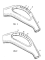
- Fig. 1 shows a part of a vacuum cleaner 1 with a suction pipe 3, the connection between a suction nozzle to a manufactures device housing, not shown.
- a handle 5 formed integrally with the intake manifold 3 is connected.
- the handle 5 has several on the surface Wells 7 on in the illustrated embodiment are round.
- knob-like Attack sections 9 formed from the by the Handle 5 formed surface protrude.
- the handle 5 is made of ABS or a PP copolymer.
- the pimpled ones Attack sections 9 are made of a thermoplastic Made of elastomer.
- the handle 5 is manufactured through a plastic injection molding process, in which the handle first 5 produced as a hollow preform with depressions 7 in which the Nubs 9 are injected.
- the handle shown in Fig. 2 has knobs 11, the have a rectangular shape with rounded corners.
- the illustrated embodiment is a mat-like insert Made from an elastomer that is manufactured separately and before the manufacture of the handle body 13 inserted into the mold becomes.
- the handle body 13 has openings 15 which are penetrated by the knobs 11 of the mat-like insert. There are several such openings 15 in the circumferential direction available.
- it is possible to make the handle from two bowl-like Form parts between which the insert is placed is so that the knobs through the existing openings grip, after which the parts are connected to each other, e.g. by screwing, gluing, welding or snapping.
- control element is designed as a handle is. It has a carrier body 19 which consists of the harder one Material exists and is manufactured by injection molding.
- An attack section 17, which functions as a handle has, is in the space between the on the support body 19th trained, opposite, attachment approaches 21 and 23 added. For this purpose, the attack section 17 at its ends recesses that match the shape of the attachment lugs 21 and 23 are adjusted. Carrier body 19 and the attack section 17 are manufactured separately and then connected with each other.
- FIG. 5 shows a cross section through a vacuum cleaner handle, whose outer contour is shaped as shown in Figure 3. is.
- the lower part there is one made of the harder material Hollow profile 3 formed through which the sucked Air is conducted.
- the upper part is on the outside a surface covering 40 consisting of an elastomer, which envelops an inner carrier body 41, which consists of a harder material, preferably the same material as used in the lower hollow section 3.
- the production this embodiment is done by the surface covering 40 as prefabricated tubular molding and into the injection molding device is inserted and positioned. Then the Sprayed vacuum cleaner handle. It is also possible to get the first Vacuum cleaner handle with molded support body 41, then in a second step with the elastomer is encapsulated.
- Fig. 4 represents a vacuum cleaner designed as a vacuum cleaner 1 with a vacuum cleaner housing 37, a dust compartment cover 25 and control elements 27, 29, 31, which act as on / off switches, Power regulation and for cable rewind serve.
- the control element 29 is designed as a push button and consists of a substantially flat support section 33, that with a nub-like surface covering 35 is provided.
- the support section is made of ABS, the Knobs are made of an elastomer, making both the required Stability of the push button as well as good usability can be achieved.
- Nubs 35 have a large coefficient of friction, the a slipping of the foot when operating the cable winder avoids.
Landscapes
- Engineering & Computer Science (AREA)
- Mechanical Engineering (AREA)
- Electric Vacuum Cleaner (AREA)
- Electric Suction Cleaners (AREA)
Applications Claiming Priority (2)
| Application Number | Priority Date | Filing Date | Title |
|---|---|---|---|
| DE10007740 | 2000-02-19 | ||
| DE2000107740 DE10007740A1 (de) | 2000-02-19 | 2000-02-19 | Staubsauger |
Publications (1)
| Publication Number | Publication Date |
|---|---|
| EP1127529A1 true EP1127529A1 (fr) | 2001-08-29 |
Family
ID=7631640
Family Applications (1)
| Application Number | Title | Priority Date | Filing Date |
|---|---|---|---|
| EP00128236A Withdrawn EP1127529A1 (fr) | 2000-02-19 | 2000-12-27 | Aspirateur |
Country Status (2)
| Country | Link |
|---|---|
| EP (1) | EP1127529A1 (fr) |
| DE (1) | DE10007740A1 (fr) |
Cited By (10)
| Publication number | Priority date | Publication date | Assignee | Title |
|---|---|---|---|---|
| WO2003073904A1 (fr) * | 2002-03-05 | 2003-09-12 | BSH Bosch und Siemens Hausgeräte GmbH | Appareil menager, notamment un aspirateur |
| EP1413239A3 (fr) * | 2002-10-25 | 2004-05-12 | Miele & Cie. KG | Poignée sur le fût d'un aspirateur |
| EP1297776A3 (fr) * | 2001-10-01 | 2005-01-05 | BSH Bosch und Siemens Hausgeräte GmbH | Dispositif pour commander un appareil électrique |
| EP1297775A3 (fr) * | 2001-10-01 | 2005-06-15 | BSH Bosch und Siemens Hausgeräte GmbH | Aspirateur avec plusieurs elements de commande |
| WO2005092017A3 (fr) * | 2004-03-19 | 2006-10-12 | Electrolux Home Care Prod Na | Aspirateur a poignee circulaire |
| CN1322960C (zh) * | 2004-04-22 | 2007-06-27 | 胡厚飞 | 结构改良的工具盒 |
| USD549905S1 (en) | 2006-08-18 | 2007-08-28 | Electrolux Homecare Products, Ltd. | Handle for a vacuum cleaner |
| DE102009015432A1 (de) | 2009-03-28 | 2010-09-30 | Braun Gmbh | Oberflächenstruktur für ein Arbeitsgerät |
| DE102009015433A1 (de) | 2009-03-28 | 2010-09-30 | Braun Gmbh | Griffbereich für ein Arbeitsgerät |
| WO2014031209A1 (fr) * | 2012-08-24 | 2014-02-27 | Feinstein Patents Llc | Dispositif d'amortissement de vibrations et de pression destiné à des poignées de préhension et à des mécanismes de direction |
Families Citing this family (2)
| Publication number | Priority date | Publication date | Assignee | Title |
|---|---|---|---|---|
| DE20118711U1 (de) | 2001-11-16 | 2002-02-28 | Wessel-Werk GmbH, 51580 Reichshof | Bodendüse für Staubsauger |
| DE102009046224B4 (de) | 2009-10-30 | 2013-02-21 | BSH Bosch und Siemens Hausgeräte GmbH | Handgriff für einen Staubsauger |
Citations (8)
| Publication number | Priority date | Publication date | Assignee | Title |
|---|---|---|---|---|
| US1908834A (en) * | 1927-12-29 | 1933-05-16 | Electrolux Corp | Handle |
| US2786920A (en) * | 1954-04-30 | 1957-03-26 | Royal Appliance Mfg | Suction cleaner handle construction |
| FR1574572A (fr) * | 1967-11-24 | 1969-07-11 | ||
| DE8020858U1 (de) * | 1980-08-04 | 1980-11-06 | Siemens Ag, 1000 Berlin Und 8000 Muenchen | Staubsauger mit zwei Drucktasten zur Betätigung von elektrischen und/oder mechanischen Vorrichtungen |
| EP0208942A2 (fr) * | 1985-07-13 | 1987-01-21 | Wera-Werk Hermann Werner GmbH & Co. | Poignée |
| US5261665A (en) * | 1992-02-11 | 1993-11-16 | Robert A. Paley, Inc. | Golf club grip formed of a plurality of materials and method of manufacture thereof |
| DE9417294U1 (de) * | 1994-10-27 | 1994-12-15 | Vileda GmbH, 69469 Weinheim | Handhabungsstiel für Geräte |
| JPH0731568A (ja) * | 1993-07-26 | 1995-02-03 | Sharp Corp | 電気掃除機 |
Family Cites Families (3)
| Publication number | Priority date | Publication date | Assignee | Title |
|---|---|---|---|---|
| DE29615176U1 (de) * | 1996-08-31 | 1996-12-19 | Alfred Kärcher GmbH & Co, 71364 Winnenden | Handspritzpistole für ein Hochdruckreinigungsgerät |
| DE29720608U1 (de) * | 1997-11-21 | 1998-02-19 | Heinrich Betz KG, 42477 Radevormwald | Werkzeugheft |
| DE29906460U1 (de) * | 1999-04-12 | 1999-08-05 | Lee, Shih-Yao, Changhua | Harz-Schraubendreher-Griffkonstruktion |
-
2000
- 2000-02-19 DE DE2000107740 patent/DE10007740A1/de not_active Ceased
- 2000-12-27 EP EP00128236A patent/EP1127529A1/fr not_active Withdrawn
Patent Citations (8)
| Publication number | Priority date | Publication date | Assignee | Title |
|---|---|---|---|---|
| US1908834A (en) * | 1927-12-29 | 1933-05-16 | Electrolux Corp | Handle |
| US2786920A (en) * | 1954-04-30 | 1957-03-26 | Royal Appliance Mfg | Suction cleaner handle construction |
| FR1574572A (fr) * | 1967-11-24 | 1969-07-11 | ||
| DE8020858U1 (de) * | 1980-08-04 | 1980-11-06 | Siemens Ag, 1000 Berlin Und 8000 Muenchen | Staubsauger mit zwei Drucktasten zur Betätigung von elektrischen und/oder mechanischen Vorrichtungen |
| EP0208942A2 (fr) * | 1985-07-13 | 1987-01-21 | Wera-Werk Hermann Werner GmbH & Co. | Poignée |
| US5261665A (en) * | 1992-02-11 | 1993-11-16 | Robert A. Paley, Inc. | Golf club grip formed of a plurality of materials and method of manufacture thereof |
| JPH0731568A (ja) * | 1993-07-26 | 1995-02-03 | Sharp Corp | 電気掃除機 |
| DE9417294U1 (de) * | 1994-10-27 | 1994-12-15 | Vileda GmbH, 69469 Weinheim | Handhabungsstiel für Geräte |
Non-Patent Citations (1)
| Title |
|---|
| PATENT ABSTRACTS OF JAPAN vol. 1995, no. 05 30 June 1995 (1995-06-30) * |
Cited By (18)
| Publication number | Priority date | Publication date | Assignee | Title |
|---|---|---|---|---|
| EP1297776A3 (fr) * | 2001-10-01 | 2005-01-05 | BSH Bosch und Siemens Hausgeräte GmbH | Dispositif pour commander un appareil électrique |
| EP1297775A3 (fr) * | 2001-10-01 | 2005-06-15 | BSH Bosch und Siemens Hausgeräte GmbH | Aspirateur avec plusieurs elements de commande |
| US7140067B2 (en) | 2002-03-05 | 2006-11-28 | Bsh Bosch Und Siemens Hausgeraete Gmbh | Vacuum cleaner handle and stiffening element |
| WO2003073904A1 (fr) * | 2002-03-05 | 2003-09-12 | BSH Bosch und Siemens Hausgeräte GmbH | Appareil menager, notamment un aspirateur |
| EP1413239A3 (fr) * | 2002-10-25 | 2004-05-12 | Miele & Cie. KG | Poignée sur le fût d'un aspirateur |
| GB2425047B (en) * | 2004-03-19 | 2007-12-27 | Electrolux Home Care Prod Na | Circular vacuum handle |
| WO2005092017A3 (fr) * | 2004-03-19 | 2006-10-12 | Electrolux Home Care Prod Na | Aspirateur a poignee circulaire |
| CN1322960C (zh) * | 2004-04-22 | 2007-06-27 | 胡厚飞 | 结构改良的工具盒 |
| USD549905S1 (en) | 2006-08-18 | 2007-08-28 | Electrolux Homecare Products, Ltd. | Handle for a vacuum cleaner |
| DE102009015432A1 (de) | 2009-03-28 | 2010-09-30 | Braun Gmbh | Oberflächenstruktur für ein Arbeitsgerät |
| DE102009015433A1 (de) | 2009-03-28 | 2010-09-30 | Braun Gmbh | Griffbereich für ein Arbeitsgerät |
| WO2010113064A1 (fr) | 2009-03-28 | 2010-10-07 | Braun Gmbh | Structure de surface destinée à un dispositif de travail |
| US8389102B2 (en) | 2009-03-28 | 2013-03-05 | Braun Gmbh | Gripping area for a working device |
| US8420203B2 (en) | 2009-03-28 | 2013-04-16 | Braun Gmbh | Surface structure for a working device |
| RU2492995C2 (ru) * | 2009-03-28 | 2013-09-20 | БРАУН ГмбХ | Область захвата для технического устройства |
| RU2492996C2 (ru) * | 2009-03-28 | 2013-09-20 | БРАУН ГмбХ | Конструктивный компонент поверхности для технического устройства |
| WO2014031209A1 (fr) * | 2012-08-24 | 2014-02-27 | Feinstein Patents Llc | Dispositif d'amortissement de vibrations et de pression destiné à des poignées de préhension et à des mécanismes de direction |
| US8881347B2 (en) | 2012-08-24 | 2014-11-11 | Feinstein Patents Llc | Vibration and pressure damping device for gripping handles and steering mechanisms |
Also Published As
| Publication number | Publication date |
|---|---|
| DE10007740A1 (de) | 2001-08-30 |
Similar Documents
| Publication | Publication Date | Title |
|---|---|---|
| EP1127529A1 (fr) | Aspirateur | |
| WO2000064642A1 (fr) | Element de poignee souple pour machines portables electriques | |
| DE2649329A1 (de) | Kraftfahrzeuglenkstockschalter | |
| DE10029955C2 (de) | Weichfühliger Schnappgriff für ein Kraftfahrzeug | |
| WO2003073904A1 (fr) | Appareil menager, notamment un aspirateur | |
| EP0681444A1 (fr) | Appareil pour l'entretien de sols, notamment aspirateur, pourvu de poils de brosserie disposes de preference sur le bord exterieur et diriges vers le bas | |
| DE4102631C2 (de) | Drucktastenschalter | |
| DE20212255U1 (de) | Mehrfach-Tastschalter | |
| EP1304714B1 (fr) | Commutateur electrique | |
| EP1151451B1 (fr) | Bouton-poussoir | |
| EP1297775B1 (fr) | Aspirateur avec plusieurs elements de commande | |
| EP2957207B1 (fr) | Poignée d'un aspirateur et aspirateur doté d'une telle poignée | |
| DE2134265C2 (de) | Fahrzeug-Fernsprech-Handapparat und Auflage für diesen Apparat | |
| EP3560404B1 (fr) | Appareil de nettoyage | |
| EP1240655A1 (fr) | Commutateur electrique | |
| DE19950367C1 (de) | Drucktaster mit federndem Dichtelement | |
| WO2007140865A1 (fr) | Aspirateur avec pièce de boîtier comportant un support et un élément d'emboutissage | |
| DE4431937A1 (de) | Schalter | |
| DE10148513B4 (de) | Vorrichtung zur Steuerung eines elektrischen Gerätes | |
| DE10156089A1 (de) | Elektrisches Haushaltsgerät | |
| DE102025121440A1 (de) | Handgeführtes Elektrogerät | |
| DE10250051B3 (de) | Handgriff an einem Stiel eines Staubsaugers | |
| DE10130251C1 (de) | Drucktastenschaltergehäuse und Drucktastenschalter | |
| DE3515920C2 (de) | Staubsauger mit einem längsgeteilten Handgriff | |
| CH625912A5 (en) | Carrying device for electrical accumulators, and a tool for producing such a device |
Legal Events
| Date | Code | Title | Description |
|---|---|---|---|
| PUAI | Public reference made under article 153(3) epc to a published international application that has entered the european phase |
Free format text: ORIGINAL CODE: 0009012 |
|
| AK | Designated contracting states |
Kind code of ref document: A1 Designated state(s): DE ES FR GB IT SE Kind code of ref document: A1 Designated state(s): AT BE CH CY DE DK ES FI FR GB GR IE IT LI LU MC NL PT SE TR |
|
| AX | Request for extension of the european patent |
Free format text: AL;LT;LV;MK;RO;SI |
|
| 17P | Request for examination filed |
Effective date: 20020116 |
|
| AKX | Designation fees paid |
Free format text: DE ES FR GB IT SE |
|
| STAA | Information on the status of an ep patent application or granted ep patent |
Free format text: STATUS: THE APPLICATION IS DEEMED TO BE WITHDRAWN |
|
| 18D | Application deemed to be withdrawn |
Effective date: 20040701 |