EP3560404B1 - Appareil de nettoyage - Google Patents
Appareil de nettoyage Download PDFInfo
- Publication number
- EP3560404B1 EP3560404B1 EP19167542.0A EP19167542A EP3560404B1 EP 3560404 B1 EP3560404 B1 EP 3560404B1 EP 19167542 A EP19167542 A EP 19167542A EP 3560404 B1 EP3560404 B1 EP 3560404B1
- Authority
- EP
- European Patent Office
- Prior art keywords
- handle
- cleaning device
- accessory
- cleaning
- connection
- Prior art date
- Legal status (The legal status is an assumption and is not a legal conclusion. Google has not performed a legal analysis and makes no representation as to the accuracy of the status listed.)
- Active
Links
Images


Classifications
-
- A—HUMAN NECESSITIES
- A47—FURNITURE; DOMESTIC ARTICLES OR APPLIANCES; COFFEE MILLS; SPICE MILLS; SUCTION CLEANERS IN GENERAL
- A47L—DOMESTIC WASHING OR CLEANING; SUCTION CLEANERS IN GENERAL
- A47L9/00—Details or accessories of suction cleaners, e.g. mechanical means for controlling the suction or for effecting pulsating action; Storing devices specially adapted to suction cleaners or parts thereof; Carrying-vehicles specially adapted for suction cleaners
- A47L9/32—Handles
- A47L9/325—Handles for wheeled suction cleaners with steering handle
-
- A—HUMAN NECESSITIES
- A47—FURNITURE; DOMESTIC ARTICLES OR APPLIANCES; COFFEE MILLS; SPICE MILLS; SUCTION CLEANERS IN GENERAL
- A47L—DOMESTIC WASHING OR CLEANING; SUCTION CLEANERS IN GENERAL
- A47L5/00—Structural features of suction cleaners
- A47L5/12—Structural features of suction cleaners with power-driven air-pumps or air-compressors, e.g. driven by motor vehicle engine vacuum
- A47L5/22—Structural features of suction cleaners with power-driven air-pumps or air-compressors, e.g. driven by motor vehicle engine vacuum with rotary fans
- A47L5/28—Suction cleaners with handles and nozzles fixed on the casings, e.g. wheeled suction cleaners with steering handle
-
- A—HUMAN NECESSITIES
- A47—FURNITURE; DOMESTIC ARTICLES OR APPLIANCES; COFFEE MILLS; SPICE MILLS; SUCTION CLEANERS IN GENERAL
- A47L—DOMESTIC WASHING OR CLEANING; SUCTION CLEANERS IN GENERAL
- A47L9/00—Details or accessories of suction cleaners, e.g. mechanical means for controlling the suction or for effecting pulsating action; Storing devices specially adapted to suction cleaners or parts thereof; Carrying-vehicles specially adapted for suction cleaners
-
- A—HUMAN NECESSITIES
- A47—FURNITURE; DOMESTIC ARTICLES OR APPLIANCES; COFFEE MILLS; SPICE MILLS; SUCTION CLEANERS IN GENERAL
- A47L—DOMESTIC WASHING OR CLEANING; SUCTION CLEANERS IN GENERAL
- A47L9/00—Details or accessories of suction cleaners, e.g. mechanical means for controlling the suction or for effecting pulsating action; Storing devices specially adapted to suction cleaners or parts thereof; Carrying-vehicles specially adapted for suction cleaners
- A47L9/02—Nozzles
-
- A—HUMAN NECESSITIES
- A47—FURNITURE; DOMESTIC ARTICLES OR APPLIANCES; COFFEE MILLS; SPICE MILLS; SUCTION CLEANERS IN GENERAL
- A47L—DOMESTIC WASHING OR CLEANING; SUCTION CLEANERS IN GENERAL
- A47L9/00—Details or accessories of suction cleaners, e.g. mechanical means for controlling the suction or for effecting pulsating action; Storing devices specially adapted to suction cleaners or parts thereof; Carrying-vehicles specially adapted for suction cleaners
- A47L9/32—Handles
-
- A—HUMAN NECESSITIES
- A47—FURNITURE; DOMESTIC ARTICLES OR APPLIANCES; COFFEE MILLS; SPICE MILLS; SUCTION CLEANERS IN GENERAL
- A47L—DOMESTIC WASHING OR CLEANING; SUCTION CLEANERS IN GENERAL
- A47L9/00—Details or accessories of suction cleaners, e.g. mechanical means for controlling the suction or for effecting pulsating action; Storing devices specially adapted to suction cleaners or parts thereof; Carrying-vehicles specially adapted for suction cleaners
- A47L9/32—Handles
- A47L9/322—Handles for hand-supported suction cleaners
Definitions
- the invention relates to a cleaning device with a housing, a cleaning accessory having a connection piece and an accessory connection formed on the housing for detachable connection to the connection piece of the cleaning accessory, the accessory connection facing a surface to be cleaned in relation to a normal usage position of the cleaning device, the cleaning device has a handle detachably arranged in the area of the accessory connection.
- Cleaning devices of the aforementioned type are well known in the prior art. These can be, for example, vacuum cleaners or damp mops. Cleaning devices of this type usually have a base device with a handle and/or a guide handle for guiding the cleaning device over a surface to be cleaned. During cleaning, the base unit stands, for example, on an attachment that is connected to the accessory connection and can have a brush or the like. In addition, the base unit can also be used to clean above-ground surfaces, in which case the base unit is then usually supported or guided with the assistance of a second hand.
- the publication DE 10 2015 118 621 A1 discloses, for example, a cleaning device with a guide handle arranged on a handle and an additional handle arranged on the device housing, which can be pivoted from a rest position into a use position is.
- This additional handle can be used to carry the cleaning tool away or to guide it during an above floor cleaning.
- a handle base of the handle is arranged on the accessory connection and/or a connection piece of a cleaning accessory and is clamped between the accessory connection and the connection piece.
- a handle base of the handle is arranged on the accessory connector and/or a connector of a cleaning accessory and is clamped between the accessory connector and the connector.
- the handle has a handle base which connects to a handle portion of the handle.
- the handle base is used to attach the handle to the cleaning device, while the handle portion is used for a user to grasp the handle.
- the handle base may be placed on either the accessory port for attachment to the cleaning implement and/or a cleaning accessory, which in turn may be connected to the accessory port.
- the handle base of the handle is between the accessory connector and the connector of the Clamped cleaning accessories, in which case the definition of the handle base of the handle on the cleaning device is carried out simultaneously with the attachment of the connecting piece of the cleaning accessories to the accessory connection.
- the material thickness of the handle base is advantageously selected such that the base device is not excessively spaced from the cleaning accessory, but rather the user can preferably proceed in the usual way during the connection process and while also essentially the same haptic impression when reaching an end position of the accessory on the cleaning device.
- damping and/or play can be minimized between the cleaning accessory and the accessory connection, ie for example an attachment and a base unit of the cleaning device.
- the cleaning device has a handle on an end housing area, on which a cleaning accessory is usually arranged.
- This end area faces the surface to be cleaned during normal floor cleaning using the cleaning device.
- the user of the cleaning device no longer has to grip the housing directly with his hand, which is often difficult due to the size of the cleaning device, but has an additional handle by means of which he can guide the cleaning device safely and accurately. This effectively prevents a pendulum movement of the cleaning device and thus, for example, accidental bumping into objects in the vicinity.
- the handle is detachably arranged on the cleaning device, in particular the accessory connection, so that the handle can optionally also be detached from the cleaning device, for example if it is not needed for a longer period of time.
- the handle can be easily detached from the cleaning device, i.e. from removed from the accessory port. If required, it is also possible to reattach the handle to the cleaning device.
- the term "in the area of the accessory connection” means here, for example, that the handle makes contact with the accessory connection of the cleaning device at least over a partial area, for example resting flat on it, or touching it only tangentially, or arranged adjacent to it or also attached to a cleaning accessory , which in turn is connected to the accessory connector, so that when the cleaning accessory is connected, the handle also comes into contact with the cleaning device.
- the cleaning device is a vacuum cleaner with a dust chamber, a fan and an accessory connection, with a suction channel being formed between the accessory connection and the fan, through which suction material can be conveyed into the dust chamber during suction operation of the cleaning device.
- the accessory connection of the cleaning device, to which the cleaning accessory can be connected also has a suction opening or a suction channel connection through which a flow connection can be established between the accessory and the fan of the cleaning device.
- the accessory connection can thus optionally have direct contact with surfaces or objects to be cleaned when using the cleaning device without a connected accessory, for example to clean room corners, skirting boards, upholstered furniture or the like.
- the cleaning device for these or others Tasks are used in combination with a cleaning accessory connected to the accessory port.
- the cleaning accessory can be, for example, an upholstery brush or another cleaning attachment.
- the cleaning device can also be a wiping device, a combined suction-wiping device, a polishing or polishing device or something else.
- the invention is suitable for all cleaning devices that are also designed for above-floor cleaning, in which the cleaning device is not supported by the surface to be cleaned, i. H. does not rest on it with its entire weight.
- the handle base has a through-opening through which a partial area of the housing of the cleaning device and/or the cleaning accessory is guided.
- the accessory connection and/or the connection piece of the cleaning accessory can be passed through the through-opening of the handle base.
- the handle base thus has a through hole for pushing through a portion of the housing or the accessory.
- the handle base can be ring-shaped and placed against a cylindrical portion of the housing and/or the cleaning accessory from the outside.
- a handle part of the handle which is used for the user to grasp the handle, protrudes beyond the contour of the cleaning device in the relevant area, so that the user can grasp the cleaning device by the handle part.
- the handle be formed from a flexible material at least in an intermediate area between a handle base attached to the cleaning appliance and a handle part designed to grip a user's hand and/or the handle portion is displaceable relative to the handle base.
- the handle can be made of an elastomer or rubber part as a whole, or only in the intermediate area mentioned.
- the material should be tear-resistant and, if necessary, be as thin or deformable as possible in the area of the handle base in order to allow the handle to be arranged on the cleaning device without significantly changing the geometric dimensions of the accessory connection or the connecting piece, in particular an arrangement of the handle base between the accessory connection and the to allow connector.
- the handle base When using an elastic material as the handle base, there is also the advantage that any play that may be present in the fastening area of the connection piece and the accessory connection is taken out of the system and the two parts are connected to one another without wobbling.
- the entire handle, but in particular the intermediate area can be made at least partially of rubber or an elastomer.
- a plastic film for example PET film, to produce the handle.
- a two-component solution can also be provided in which the handle base is formed from a thin PET film, which merges into an elastic material in the intermediate area between the handle base and the handle part, from which the handle part then consists.
- the elastic material can also ensure that the handle part is displaced in a preferred direction when a user is no longer gripping the handle part.
- the handle can also be made of an elastic material, at least in the intermediate area.
- a shape of a contact surface of the handle that can be placed against the cleaning device corresponds to a shape of a surface area of the cleaning device intended for contact with the contact surface.
- the handle or at least the handle part of the handle is formed according to this embodiment as a molded part, the shape of which external shape of the cleaning device, to which the handle part is applied, corresponds.
- the handle part can be placed flat against the cleaning device in a non-use position. As a result of this configuration, the handle part does not protrude from the housing when it is not in use.
- the handle can be formed entirely from an elastic material, in particular rubber or an elastomer as a molded body.
- the restoring force applied to the molded part causes the grip part to lie flat against the corresponding surface area of the cleaning device and, if necessary, can be gripped by a user and, due to the flexibility of the material, moved from the non-use position into a handling position that can be moved due to the geometries of the handle base, handle part and, if necessary, an intermediate area between these and due to the weight forces acting on it.
- the handle part can preferably also be adapted to the shape and size of a hand of the user.
- a handle part of the handle is pivotably mounted on a pivot axis assigned to a handle base of the handle, so that the handle part can be swiveled away from the cleaning device and towards the cleaning device.
- both the handle base and the handle part of the handle can be rigid and can be pivoted relative to one another by rotation about the pivot axis.
- the handle base can be arranged either on the accessory connection of the housing of the cleaning device, the connection piece of a cleaning accessory or between them will.
- the handle base can in turn be a ring-shaped element which is pushed from the outside onto a preferably conical partial area of the accessory connection or the connection piece.
- the grip base can be formed from a rigid material, for example a hard plastic, or again from an elastic material, which at the same time serves to reduce or eliminate play, as a damping element or as a sealing element.
- the handle when the handle is not in use it can be placed against the cleaning device by a restoring force inherent in the material of the handle and/or by a restoring element assigned to the handle.
- the handle can be a molded part made of elastic material, which has an intrinsic restoring force due to the material properties, which means that the preformed handle returns to its preferred position if a force applied by a user is removed, which here, for example, is flat against the housing corresponds to the non-use position created by the cleaning device.
- the handle can alternatively or additionally be assigned a separate restoring element, which is arranged, for example, between the accessory connection and the grip part or the connection piece and the grip part.
- the restoring element can be a spring element, for example.
- the reset element can be corresponding magnetic elements which are assigned to the handle part on the one hand and to the cleaning device on the other hand.
- the user can move the grip part away from the cleaning device by overcoming the restoring force, with the grip part being automatically placed back on the cleaning device following the restoring force when the user's force is no longer applied.
- the provision of the handle when not in use of the cleaning device prevents the unused handle of the Cleaning device protrudes and, for example, accidentally bumps into objects in the area.
- the cleaning device has a second handle on a housing area facing away from the accessory connection, the distance between the two handles being at least 20 cm.
- the detachably arranged handle is not the only handle of the cleaning device, but advantageously supplements a further handle which is arranged on another, remote partial area of the housing of the cleaning device.
- a distance can be selected which is significantly greater than 20 cm, for example 30 cm, 35 cm, 40 cm or even greater .
- a distance of at least 20 cm between the handles prevents the cleaning device from tilting or swinging back and forth unintentionally. In this configuration, the user grips two partial areas of the cleaning device that are distant from one another, so that stable and advantageous guidance of the cleaning device is possible.
- the cleaning device 1 shown is designed as a hand-held household vacuum cleaner, which can be used both for cleaning floor surfaces and for cleaning above-floor surfaces.
- the cleaning device 1 has a housing 2 with an accessory connection 3, to which an accessory 5 designed as an attachment is connected here.
- the accessory 5 has a connection piece 4 which is used for arrangement on the accessory connection 3 .
- the cleaning device 1 has a dust chamber 7 , a fan 8 and a suction channel 9 in the usual way, which is guided from the accessory connection 3 via the dust chamber 7 to the fan 8 .
- the suction channel 9 transitions into a corresponding suction channel (not shown) of the accessory 5 .
- the cleaning device 1 has a handle 21 on which a handle 22 is arranged, which is used to guide the cleaning device 1 while cleaning a floor surface.
- a switch 23 is also formed on the handle 22 and is used, for example, to switch the blower 8 on and off.
- the accessory 5 of the cleaning device 1 serving as an attachment has wheels 20 which serve to move the cleaning device 1 over a surface to be cleaned with little friction.
- the cleaning device 1 has a further handle 19 which - like the handle 22 - is in the figure 1 shown position of use is arranged in an upper area of the housing 2 of the cleaning device 1, here for example on a housing area 18 at a height between the dust chamber 7 and the fan 8.
- the cleaning device 1 In order to hold the cleaning device 1 , in particular when cleaning above the floor, the cleaning device 1 also has a handle 6 which is arranged in the area of the accessory connection 3 of the housing 2 . A portion of this handle 6 is clamped here between the accessory connection 3 of the housing 2 and the connection piece 4 of the accessory 5, so that when the accessory connection 3 and connection piece 4 are connected, the handle 6 is also fixed at the same time.
- the handle 6 has a handle base 10 (see Fig figure 2 ) and a handle part 13, in the representation according to figure 1 only the outwardly projecting handle part 13 is visible.
- the handle 6 is made here, for example, entirely from an elastic material, for example rubber, and is designed as an elastic molded part, which is in the figure 1 illustrated non-use position of the handle 6 corresponding to a surface area 15 (see figure 3 ) of the housing 2 applies.
- the handle part 13 has a contact surface 14 (see figure 2 ), which lies flat against the surface area 15 in the non-use position.
- FIG 2 shows the handle 6 arranged on the cleaning accessory 5.
- the handle base 10 of the handle 6 is pushed over a portion 11 of the connecting piece 4 for attachment to the cleaning accessory 5.
- the handle base 10 has a through-opening whose inner contour corresponds to an outer contour of the partial area 11 .
- the cleaning accessory 5 with the in figure 2 illustrated position and orientation of the handle 6 attached to the accessory port 3 of the cleaning device 1.
- the accessory connection 3 of the cleaning device 1 is pushed onto the connection piece 4 of the accessory 5.
- this also connects the suction channel 9 of the cleaning device 1 to the partial area 11 of the connection piece 4.
- the handle part 13 of the handle 6 remains on the outside when the cleaning accessory 5 is attached to the cleaning device 1, so that the handle part 13 can be gripped by a user.
- the handle part 13 has a handle opening 24 into which a user can reach with his hand.
- the handle 6 is made, for example, in one piece from the same material, here for example rubber or an elastomer.
- the handle base 10 and the handle part 13 are connected via an intermediate area 12, which intermediate area 12 represents a pivoting area over which the handle part 13 can be pivoted relative to the handle base 10 and thus also to the cleaning device 1 or the cleaning accessory 5.
- the Figures 3 and 4 show the handle part 13 in different pivot positions, namely on the one hand in a non-use position ( figure 3 ) and on the other hand in a position of use ( figure 4 ).
- the handle part 13 In the non-use position, the handle part 13 is not exposed to the user or the weight of the cleaning device 1 . Therefore, the handle part 13 is located there in the preferred position applied to the surface area 15 of the housing 2, which corresponds to the unloaded shape of the handle 6.
- the handle part 13 deforms due to the elastic material, so that the shape of the handle opening 24 may also be adapted to the user's hand, depending on the rigidity of the material.
- the handle base 10 can also serve as a damping element or sealing element. Furthermore, the handle base 10 can also eliminate or minimize play existing between the housing 2 and the cleaning accessory 5 .
- the handle base 10 preferably has a ductile material.
- the handle base 10 should have the smallest possible material thickness. In particular, a thickness of the handle base 10 of less than 2 mm, in particular less than 1 mm, is recommended.
- the handle 6 from two different components, namely, on the one hand, from a particularly thin handle base 10, which can be formed from a thin film, for example, and on the other hand from a handle part 13, which consists of a thicker rubber material.
- the intermediate portion 12 formed between the handle base 10 and the handle portion 13 may also be formed of rubber to withstand pivotal stress of the handle 6.
- the film material of the grip base 10 can be PET (polyethylene terephthalate), for example.
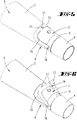
- the Figures 5 and 6 Figure 1 shows a further embodiment of the invention, in which the handle 6 is made up of a handle part 13 and a handle base 10 which are pivotably arranged relative to one another.
- the handle base 10 has a pivot axis 16 on which the handle part 13 is pivotably mounted.
- the handle part 13 and the handle base 10 are both made of a hard plastic here, for example.
- the handle base 10 is designed here in the manner of a ring, which can be pushed onto the accessory connection 3 of the housing 2 of the cleaning device 1 from the outside.
- the accessory connection 3 is conical and widens in a direction opposite to the connection piece 4 of the cleaning accessory 5 . Therefore, the grip base 10 is automatically clamped in the end position shown when pushed onto the accessory connection 3 .
- the connecting piece 4 of the accessory 5 is then pushed and locked in front of the handle base 10 to secure this position.
- the handle part 13 is designed to correspond in shape to a surface area 15 of the housing 2 .
- the surface area 15 is provided here with a material recess, for example, into which the handle part 13 in figure 5 shown non-use position can be sunk.
- the handle part 13 is secured with the aid of a restoring element 17 which, for example, has corresponding magnets here, which are arranged in the handle part 13 and the surface area 15 of the housing 2 are.
- a spring element can also be used as a restoring element 17, for example, which pulls the handle part 13 back to the surface area 15 when a user lets go of the handle 6.
- the handle 6 is arranged detachably on the accessory connection 3 .
- the grip base 10 does not protrude between the connection piece 4 and the accessory connection 3, but is attached to the accessory connection 3 from the outside, it is not absolutely necessary for the material thickness of the grip base 10 to be as small as possible.
- handle 6 also consist of an elastic material, so that the pivot axis 16 can be omitted and the pivoting mobility of the handle part 13 is realized relative to the handle base 10 via an elastic intermediate area 12.
Landscapes
- Engineering & Computer Science (AREA)
- Mechanical Engineering (AREA)
- Cleaning Implements For Floors, Carpets, Furniture, Walls, And The Like (AREA)
- Electric Vacuum Cleaner (AREA)
- Electric Suction Cleaners (AREA)
Claims (9)
- Appareil de nettoyage (1) avec un boîtier (2), un accessoire de nettoyage (5) présentant une partie de raccordement (4) et un raccord d'accessoire (3) formé au niveau du boîtier (2) pour la liaison amovible avec la partie de raccordement (4) de l'accessoire de nettoyage (5), le raccord d'accessoire (3) étant orienté vers une surface à nettoyer par rapport à une position d'utilisation usuelle de l'appareil de nettoyage (1), l'appareil de nettoyage (1) présentant une poignée (6) agencée de manière amovible dans la zone du raccord d'accessoire (3), caractérisé en ce qu'une base de poignée (10) de la poignée (6) est agencée associée au raccord d'accessoire (3) et/ou à la partie de raccordement (4) de l'accessoire de nettoyage (5) et est serrée entre le raccord d'accessoire (3) et la partie de raccordement (4).
- Appareil de nettoyage (1) selon la revendication 1, caractérisé en ce que l'appareil de nettoyage (1) est un aspirateur avec une chambre à poussière (7), un souffleur (8) et un raccord d'accessoire (3), dans lequel un canal d'aspiration (9) est formé entre le raccord d'accessoire (3) et le souffleur (8), à travers lequel des produits aspirés peuvent être transportés dans la chambre à poussière (7) pendant un fonctionnement d'aspiration de l'appareil de nettoyage (1).
- Appareil de nettoyage (1) selon la revendication 1 ou 2, caractérisé en ce que la base de poignée (10) présente une ouverture de passage à travers laquelle passe une région partielle (11) du boîtier (2) et/ou de l'accessoire de nettoyage (5), en particulier le raccord d'accessoire (3) et/ou la partie de raccordement (4).
- Appareil de nettoyage (1) selon l'une des revendications précédentes, caractérisé en ce que la poignée (6) est formée d'un matériau flexible au moins dans une zone intermédiaire (12) entre une base de poignée (10) fixée à l'appareil de nettoyage (1) et une partie de poignée (13) conçue pour être saisie par une main d'un utilisateur et/ou la partie de poignée (13) est déplaçable par rapport à la base de poignée (10).
- Appareil de nettoyage (1) selon l'une quelconque des revendications précédentes, caractérisé en ce qu'une forme d'une surface d'appui (14) de la poignée (6) pouvant être appliquée contre l'appareil de nettoyage (1) correspond à une forme d'une zone de surface (15) de l'appareil de nettoyage (1) destiné à l'application de la surface d'appui (14).
- Appareil de nettoyage (1) selon la revendication 4 ou 5, caractérisé en ce que la partie de poignée (13) peut être appliquée à plat contre l'appareil de nettoyage (1) dans une position de non-utilisation.
- Appareil de nettoyage (1) selon l'une des revendications précédentes, caractérisé en ce qu'une partie de poignée (13) de la poignée (6) est montée pivotante à un axe de pivotement (16) associé à une base de poignée (10) de la poignée (6) de manière que la partie de poignée (13) puisse être éloignée par pivotement de l'appareil de nettoyage (1) et rapprochée par pivotement de l'appareil de nettoyage (1).
- Appareil de nettoyage (1) selon l'une des revendications précédentes, caractérisé en ce que la poignée (6), lorsqu'elle n'est pas utilisée, peut être appliquée contre l'appareil de nettoyage (1) par une force de rappel inhérente au matériau de la poignée (6) et/ou par un élément de rappel (17) associé à la poignée (6).
- Appareil de nettoyage (1) selon l'une des revendications précédentes, caractérisé en ce que l'appareil de nettoyage (1) présente une deuxième poignée (19) au niveau d'une zone de boîtier (18) éloignée du raccord d'accessoire (3), une distance entre les deux poignées (6, 19) étant d'au moins 20 cm.
Applications Claiming Priority (1)
| Application Number | Priority Date | Filing Date | Title |
|---|---|---|---|
| DE102018110221.6A DE102018110221B4 (de) | 2018-04-27 | 2018-04-27 | Reinigungsgerät |
Publications (2)
| Publication Number | Publication Date |
|---|---|
| EP3560404A1 EP3560404A1 (fr) | 2019-10-30 |
| EP3560404B1 true EP3560404B1 (fr) | 2022-08-17 |
Family
ID=66101927
Family Applications (1)
| Application Number | Title | Priority Date | Filing Date |
|---|---|---|---|
| EP19167542.0A Active EP3560404B1 (fr) | 2018-04-27 | 2019-04-05 | Appareil de nettoyage |
Country Status (6)
| Country | Link |
|---|---|
| EP (1) | EP3560404B1 (fr) |
| JP (1) | JP2019188134A (fr) |
| CN (1) | CN110403518B (fr) |
| DE (1) | DE102018110221B4 (fr) |
| ES (1) | ES2927227T3 (fr) |
| TW (1) | TW202002874A (fr) |
Families Citing this family (1)
| Publication number | Priority date | Publication date | Assignee | Title |
|---|---|---|---|---|
| DE102020121196A1 (de) | 2020-08-12 | 2022-02-17 | Vorwerk & Co. Interholding Gesellschaft mit beschränkter Haftung | Flächenbearbeitungsgerät mit einer Fernentriegelungseinrichtung für ein Vorsatzgerät |
Family Cites Families (13)
| Publication number | Priority date | Publication date | Assignee | Title |
|---|---|---|---|---|
| NL108113C (fr) * | 1956-03-29 | |||
| FR1221757A (fr) * | 1959-01-09 | 1960-06-03 | Perfectionnements aux aspirateurs du genre aspirateurs-balais | |
| DE8224611U1 (de) * | 1982-09-01 | 1982-12-09 | Vorwerk & Co Interholding Gmbh, 5600 Wuppertal | Tragegriff fuer einen handstaubsauger |
| DE9318460U1 (de) * | 1993-12-02 | 1995-03-30 | Vorwerk & Co Interholding Gmbh, 42275 Wuppertal | Elektromotorisch betriebenes Staubsauggerät mit einem teleskopierbaren Gerätestiel |
| JP3177444B2 (ja) * | 1996-04-23 | 2001-06-18 | 三洋電機株式会社 | 電気掃除機 |
| US6363571B1 (en) * | 1999-02-26 | 2002-04-02 | Pacific Steamex Cleaning Systems, Inc. | Convertible upright vacuum |
| JP2002095613A (ja) * | 2000-09-26 | 2002-04-02 | Matsushita Electric Ind Co Ltd | セントラルクリーナー |
| US6564423B2 (en) * | 2001-06-21 | 2003-05-20 | Black & Decker Inc. | Two piece upright handle assembly for a vacuum cleaner system |
| ITUD20030107A1 (it) * | 2003-05-20 | 2004-11-21 | De Longhi Spa | Apparecchiatura elettrica multifunzionale di pulizia. |
| CN100593386C (zh) * | 2003-08-22 | 2010-03-10 | 碧洁家庭护理有限公司 | 裸露地板清洁器 |
| GB2442033B (en) * | 2006-09-20 | 2011-06-22 | Dyson Technology Ltd | Motor driving apparatus |
| DE102012100042A1 (de) * | 2012-01-04 | 2013-07-04 | Miele & Cie. Kg | Akkutischsauger mit einem abnehmbaren Staubsammelbehälter |
| DE102015118621B4 (de) | 2015-10-30 | 2024-09-19 | Vorwerk & Co. Interholding Gmbh | Reinigungsgerät mit einem schwenkbaren Handgriff |
-
2018
- 2018-04-27 DE DE102018110221.6A patent/DE102018110221B4/de not_active Expired - Fee Related
-
2019
- 2019-04-05 ES ES19167542T patent/ES2927227T3/es active Active
- 2019-04-05 EP EP19167542.0A patent/EP3560404B1/fr active Active
- 2019-04-11 JP JP2019075283A patent/JP2019188134A/ja active Pending
- 2019-04-19 TW TW108113841A patent/TW202002874A/zh unknown
- 2019-04-24 CN CN201910332541.7A patent/CN110403518B/zh active Active
Also Published As
| Publication number | Publication date |
|---|---|
| EP3560404A1 (fr) | 2019-10-30 |
| CN110403518B (zh) | 2022-08-02 |
| TW202002874A (zh) | 2020-01-16 |
| DE102018110221A1 (de) | 2019-10-31 |
| ES2927227T3 (es) | 2022-11-03 |
| DE102018110221B4 (de) | 2023-08-31 |
| CN110403518A (zh) | 2019-11-05 |
| JP2019188134A (ja) | 2019-10-31 |
Similar Documents
| Publication | Publication Date | Title |
|---|---|---|
| DE10124220A1 (de) | Hilfssaugrohr-Anordnung für einen Staubsauger | |
| DE102008034458B4 (de) | Handgeführte Saugdüse zum Anschluss an einen Staubsauger und Saugdüse trennbar mit einem Düsenvorsatz | |
| DE60131136T2 (de) | Verbindungsstück für die verlängerung für einen werkzeuggriff | |
| EP3677379A1 (fr) | Machine-outil manuelle | |
| DE102018127090A1 (de) | Handgeführtes Reinigungsgerät | |
| DE19850104C1 (de) | Polsterdüse für Staubsauger | |
| EP1814430B1 (fr) | Buse d'aspiration ajustable manuellement | |
| DE102018110221B4 (de) | Reinigungsgerät | |
| DE3136401C2 (de) | Mehrzweck-Reinigungsgerät | |
| EP1482826B1 (fr) | Appareil menager, notamment un aspirateur | |
| DE102015118621B4 (de) | Reinigungsgerät mit einem schwenkbaren Handgriff | |
| DE102018116395B4 (de) | Reinigungseinrichtung mit einer Saugdüse und einem mechanischen Reinigungselement | |
| EP1252854B1 (fr) | Raccord de tuyaux pour tuyau d' aspirateur | |
| EP3623111B1 (fr) | Appareil électrique portatif doté d'une poignée pouvant être déplacée | |
| EP3449794A1 (fr) | Dispositif de nettoyage doté d'une plaque oscillante à entraînement par moteur | |
| EP3429428A1 (fr) | Dispositif poignée d'hygiène bucco-dentaire | |
| DE1172015B (de) | Kupplungseinrichtung fuer einen Staubsaugerschlauch | |
| EP2100534A1 (fr) | Dispositif de lavage et de massage | |
| EP0548605A1 (fr) | Poignée pour tuyau d'aspirateur | |
| DE102018251730A1 (de) | Handwerkzeugmaschine | |
| DE102019126020A1 (de) | Endaufsatz zur Verbindung mit einem Saugkanalendbereich, System aus einem Saugkanal eines Saugreinigungsgerätes und einem Endaufsatz sowie Saugreinigungsgerät | |
| EP3902656B1 (fr) | Machine-outil portative | |
| DE102022110399A1 (de) | Rotierender Top-Grip | |
| DE202015003673U1 (de) | Halteelementanordnung | |
| DE102025121440A1 (de) | Handgeführtes Elektrogerät |
Legal Events
| Date | Code | Title | Description |
|---|---|---|---|
| PUAI | Public reference made under article 153(3) epc to a published international application that has entered the european phase |
Free format text: ORIGINAL CODE: 0009012 |
|
| STAA | Information on the status of an ep patent application or granted ep patent |
Free format text: STATUS: THE APPLICATION HAS BEEN PUBLISHED |
|
| AK | Designated contracting states |
Kind code of ref document: A1 Designated state(s): AL AT BE BG CH CY CZ DE DK EE ES FI FR GB GR HR HU IE IS IT LI LT LU LV MC MK MT NL NO PL PT RO RS SE SI SK SM TR |
|
| AX | Request for extension of the european patent |
Extension state: BA ME |
|
| STAA | Information on the status of an ep patent application or granted ep patent |
Free format text: STATUS: REQUEST FOR EXAMINATION WAS MADE |
|
| 17P | Request for examination filed |
Effective date: 20200326 |
|
| RBV | Designated contracting states (corrected) |
Designated state(s): AL AT BE BG CH CY CZ DE DK EE ES FI FR GB GR HR HU IE IS IT LI LT LU LV MC MK MT NL NO PL PT RO RS SE SI SK SM TR |
|
| GRAP | Despatch of communication of intention to grant a patent |
Free format text: ORIGINAL CODE: EPIDOSNIGR1 |
|
| STAA | Information on the status of an ep patent application or granted ep patent |
Free format text: STATUS: GRANT OF PATENT IS INTENDED |
|
| INTG | Intention to grant announced |
Effective date: 20220405 |
|
| GRAS | Grant fee paid |
Free format text: ORIGINAL CODE: EPIDOSNIGR3 |
|
| GRAA | (expected) grant |
Free format text: ORIGINAL CODE: 0009210 |
|
| STAA | Information on the status of an ep patent application or granted ep patent |
Free format text: STATUS: THE PATENT HAS BEEN GRANTED |
|
| AK | Designated contracting states |
Kind code of ref document: B1 Designated state(s): AL AT BE BG CH CY CZ DE DK EE ES FI FR GB GR HR HU IE IS IT LI LT LU LV MC MK MT NL NO PL PT RO RS SE SI SK SM TR |
|
| REG | Reference to a national code |
Ref country code: CH Ref legal event code: EP |
|
| REG | Reference to a national code |
Ref country code: DE Ref legal event code: R096 Ref document number: 502019005304 Country of ref document: DE |
|
| REG | Reference to a national code |
Ref country code: IE Ref legal event code: FG4D Free format text: LANGUAGE OF EP DOCUMENT: GERMAN |
|
| REG | Reference to a national code |
Ref country code: AT Ref legal event code: REF Ref document number: 1511605 Country of ref document: AT Kind code of ref document: T Effective date: 20220915 |
|
| REG | Reference to a national code |
Ref country code: ES Ref legal event code: FG2A Ref document number: 2927227 Country of ref document: ES Kind code of ref document: T3 Effective date: 20221103 |
|
| REG | Reference to a national code |
Ref country code: NL Ref legal event code: MP Effective date: 20220817 |
|
| REG | Reference to a national code |
Ref country code: LT Ref legal event code: MG9D |
|
| PG25 | Lapsed in a contracting state [announced via postgrant information from national office to epo] |
Ref country code: SE Free format text: LAPSE BECAUSE OF FAILURE TO SUBMIT A TRANSLATION OF THE DESCRIPTION OR TO PAY THE FEE WITHIN THE PRESCRIBED TIME-LIMIT Effective date: 20220817 Ref country code: RS Free format text: LAPSE BECAUSE OF FAILURE TO SUBMIT A TRANSLATION OF THE DESCRIPTION OR TO PAY THE FEE WITHIN THE PRESCRIBED TIME-LIMIT Effective date: 20220817 Ref country code: PT Free format text: LAPSE BECAUSE OF FAILURE TO SUBMIT A TRANSLATION OF THE DESCRIPTION OR TO PAY THE FEE WITHIN THE PRESCRIBED TIME-LIMIT Effective date: 20221219 Ref country code: NO Free format text: LAPSE BECAUSE OF FAILURE TO SUBMIT A TRANSLATION OF THE DESCRIPTION OR TO PAY THE FEE WITHIN THE PRESCRIBED TIME-LIMIT Effective date: 20221117 Ref country code: NL Free format text: LAPSE BECAUSE OF FAILURE TO SUBMIT A TRANSLATION OF THE DESCRIPTION OR TO PAY THE FEE WITHIN THE PRESCRIBED TIME-LIMIT Effective date: 20220817 Ref country code: LV Free format text: LAPSE BECAUSE OF FAILURE TO SUBMIT A TRANSLATION OF THE DESCRIPTION OR TO PAY THE FEE WITHIN THE PRESCRIBED TIME-LIMIT Effective date: 20220817 Ref country code: LT Free format text: LAPSE BECAUSE OF FAILURE TO SUBMIT A TRANSLATION OF THE DESCRIPTION OR TO PAY THE FEE WITHIN THE PRESCRIBED TIME-LIMIT Effective date: 20220817 Ref country code: FI Free format text: LAPSE BECAUSE OF FAILURE TO SUBMIT A TRANSLATION OF THE DESCRIPTION OR TO PAY THE FEE WITHIN THE PRESCRIBED TIME-LIMIT Effective date: 20220817 |
|
| PG25 | Lapsed in a contracting state [announced via postgrant information from national office to epo] |
Ref country code: PL Free format text: LAPSE BECAUSE OF FAILURE TO SUBMIT A TRANSLATION OF THE DESCRIPTION OR TO PAY THE FEE WITHIN THE PRESCRIBED TIME-LIMIT Effective date: 20220817 Ref country code: IS Free format text: LAPSE BECAUSE OF FAILURE TO SUBMIT A TRANSLATION OF THE DESCRIPTION OR TO PAY THE FEE WITHIN THE PRESCRIBED TIME-LIMIT Effective date: 20221217 Ref country code: HR Free format text: LAPSE BECAUSE OF FAILURE TO SUBMIT A TRANSLATION OF THE DESCRIPTION OR TO PAY THE FEE WITHIN THE PRESCRIBED TIME-LIMIT Effective date: 20220817 Ref country code: GR Free format text: LAPSE BECAUSE OF FAILURE TO SUBMIT A TRANSLATION OF THE DESCRIPTION OR TO PAY THE FEE WITHIN THE PRESCRIBED TIME-LIMIT Effective date: 20221118 |
|
| PG25 | Lapsed in a contracting state [announced via postgrant information from national office to epo] |
Ref country code: SM Free format text: LAPSE BECAUSE OF FAILURE TO SUBMIT A TRANSLATION OF THE DESCRIPTION OR TO PAY THE FEE WITHIN THE PRESCRIBED TIME-LIMIT Effective date: 20220817 Ref country code: RO Free format text: LAPSE BECAUSE OF FAILURE TO SUBMIT A TRANSLATION OF THE DESCRIPTION OR TO PAY THE FEE WITHIN THE PRESCRIBED TIME-LIMIT Effective date: 20220817 Ref country code: DK Free format text: LAPSE BECAUSE OF FAILURE TO SUBMIT A TRANSLATION OF THE DESCRIPTION OR TO PAY THE FEE WITHIN THE PRESCRIBED TIME-LIMIT Effective date: 20220817 Ref country code: CZ Free format text: LAPSE BECAUSE OF FAILURE TO SUBMIT A TRANSLATION OF THE DESCRIPTION OR TO PAY THE FEE WITHIN THE PRESCRIBED TIME-LIMIT Effective date: 20220817 |
|
| REG | Reference to a national code |
Ref country code: DE Ref legal event code: R097 Ref document number: 502019005304 Country of ref document: DE |
|
| PG25 | Lapsed in a contracting state [announced via postgrant information from national office to epo] |
Ref country code: SK Free format text: LAPSE BECAUSE OF FAILURE TO SUBMIT A TRANSLATION OF THE DESCRIPTION OR TO PAY THE FEE WITHIN THE PRESCRIBED TIME-LIMIT Effective date: 20220817 Ref country code: EE Free format text: LAPSE BECAUSE OF FAILURE TO SUBMIT A TRANSLATION OF THE DESCRIPTION OR TO PAY THE FEE WITHIN THE PRESCRIBED TIME-LIMIT Effective date: 20220817 |
|
| P01 | Opt-out of the competence of the unified patent court (upc) registered |
Effective date: 20230517 |
|
| PLBE | No opposition filed within time limit |
Free format text: ORIGINAL CODE: 0009261 |
|
| STAA | Information on the status of an ep patent application or granted ep patent |
Free format text: STATUS: NO OPPOSITION FILED WITHIN TIME LIMIT |
|
| PG25 | Lapsed in a contracting state [announced via postgrant information from national office to epo] |
Ref country code: AL Free format text: LAPSE BECAUSE OF FAILURE TO SUBMIT A TRANSLATION OF THE DESCRIPTION OR TO PAY THE FEE WITHIN THE PRESCRIBED TIME-LIMIT Effective date: 20220817 |
|
| 26N | No opposition filed |
Effective date: 20230519 |
|
| PG25 | Lapsed in a contracting state [announced via postgrant information from national office to epo] |
Ref country code: SI Free format text: LAPSE BECAUSE OF FAILURE TO SUBMIT A TRANSLATION OF THE DESCRIPTION OR TO PAY THE FEE WITHIN THE PRESCRIBED TIME-LIMIT Effective date: 20220817 |
|
| REG | Reference to a national code |
Ref country code: CH Ref legal event code: PL |
|
| GBPC | Gb: european patent ceased through non-payment of renewal fee |
Effective date: 20230405 |
|
| PG25 | Lapsed in a contracting state [announced via postgrant information from national office to epo] |
Ref country code: LU Free format text: LAPSE BECAUSE OF NON-PAYMENT OF DUE FEES Effective date: 20230405 |
|
| REG | Reference to a national code |
Ref country code: BE Ref legal event code: MM Effective date: 20230430 |
|
| PG25 | Lapsed in a contracting state [announced via postgrant information from national office to epo] |
Ref country code: MC Free format text: LAPSE BECAUSE OF FAILURE TO SUBMIT A TRANSLATION OF THE DESCRIPTION OR TO PAY THE FEE WITHIN THE PRESCRIBED TIME-LIMIT Effective date: 20220817 |
|
| PG25 | Lapsed in a contracting state [announced via postgrant information from national office to epo] |
Ref country code: GB Free format text: LAPSE BECAUSE OF NON-PAYMENT OF DUE FEES Effective date: 20230405 |
|
| PG25 | Lapsed in a contracting state [announced via postgrant information from national office to epo] |
Ref country code: MC Free format text: LAPSE BECAUSE OF FAILURE TO SUBMIT A TRANSLATION OF THE DESCRIPTION OR TO PAY THE FEE WITHIN THE PRESCRIBED TIME-LIMIT Effective date: 20220817 Ref country code: LI Free format text: LAPSE BECAUSE OF NON-PAYMENT OF DUE FEES Effective date: 20230430 Ref country code: GB Free format text: LAPSE BECAUSE OF NON-PAYMENT OF DUE FEES Effective date: 20230405 Ref country code: CH Free format text: LAPSE BECAUSE OF NON-PAYMENT OF DUE FEES Effective date: 20230430 |
|
| REG | Reference to a national code |
Ref country code: IE Ref legal event code: MM4A |
|
| PG25 | Lapsed in a contracting state [announced via postgrant information from national office to epo] |
Ref country code: BE Free format text: LAPSE BECAUSE OF NON-PAYMENT OF DUE FEES Effective date: 20230430 |
|
| PG25 | Lapsed in a contracting state [announced via postgrant information from national office to epo] |
Ref country code: IE Free format text: LAPSE BECAUSE OF NON-PAYMENT OF DUE FEES Effective date: 20230405 |
|
| PG25 | Lapsed in a contracting state [announced via postgrant information from national office to epo] |
Ref country code: IE Free format text: LAPSE BECAUSE OF NON-PAYMENT OF DUE FEES Effective date: 20230405 |
|
| PG25 | Lapsed in a contracting state [announced via postgrant information from national office to epo] |
Ref country code: BG Free format text: LAPSE BECAUSE OF FAILURE TO SUBMIT A TRANSLATION OF THE DESCRIPTION OR TO PAY THE FEE WITHIN THE PRESCRIBED TIME-LIMIT Effective date: 20220817 |
|
| PG25 | Lapsed in a contracting state [announced via postgrant information from national office to epo] |
Ref country code: BG Free format text: LAPSE BECAUSE OF FAILURE TO SUBMIT A TRANSLATION OF THE DESCRIPTION OR TO PAY THE FEE WITHIN THE PRESCRIBED TIME-LIMIT Effective date: 20220817 |
|
| REG | Reference to a national code |
Ref country code: AT Ref legal event code: MM01 Ref document number: 1511605 Country of ref document: AT Kind code of ref document: T Effective date: 20240405 |
|
| PGFP | Annual fee paid to national office [announced via postgrant information from national office to epo] |
Ref country code: DE Payment date: 20250417 Year of fee payment: 7 |
|
| PGFP | Annual fee paid to national office [announced via postgrant information from national office to epo] |
Ref country code: ES Payment date: 20250519 Year of fee payment: 7 |
|
| PGFP | Annual fee paid to national office [announced via postgrant information from national office to epo] |
Ref country code: IT Payment date: 20250430 Year of fee payment: 7 |
|
| PGFP | Annual fee paid to national office [announced via postgrant information from national office to epo] |
Ref country code: FR Payment date: 20250422 Year of fee payment: 7 |
|
| PG25 | Lapsed in a contracting state [announced via postgrant information from national office to epo] |
Ref country code: AT Free format text: LAPSE BECAUSE OF NON-PAYMENT OF DUE FEES Effective date: 20240405 |
|
| PG25 | Lapsed in a contracting state [announced via postgrant information from national office to epo] |
Ref country code: CY Free format text: LAPSE BECAUSE OF FAILURE TO SUBMIT A TRANSLATION OF THE DESCRIPTION OR TO PAY THE FEE WITHIN THE PRESCRIBED TIME-LIMIT; INVALID AB INITIO Effective date: 20190405 |
|
| PG25 | Lapsed in a contracting state [announced via postgrant information from national office to epo] |
Ref country code: HU Free format text: LAPSE BECAUSE OF FAILURE TO SUBMIT A TRANSLATION OF THE DESCRIPTION OR TO PAY THE FEE WITHIN THE PRESCRIBED TIME-LIMIT; INVALID AB INITIO Effective date: 20190405 |
|
| PG25 | Lapsed in a contracting state [announced via postgrant information from national office to epo] |
Ref country code: TR Free format text: LAPSE BECAUSE OF FAILURE TO SUBMIT A TRANSLATION OF THE DESCRIPTION OR TO PAY THE FEE WITHIN THE PRESCRIBED TIME-LIMIT Effective date: 20220817 |
|
| PGFP | Annual fee paid to national office [announced via postgrant information from national office to epo] |
Ref country code: AT Payment date: 20260410 Year of fee payment: 5 |