EP1127594A2 - Jeu de puzzle en forme d'un dispositif mécanique - Google Patents
Jeu de puzzle en forme d'un dispositif mécanique Download PDFInfo
- Publication number
- EP1127594A2 EP1127594A2 EP01104116A EP01104116A EP1127594A2 EP 1127594 A2 EP1127594 A2 EP 1127594A2 EP 01104116 A EP01104116 A EP 01104116A EP 01104116 A EP01104116 A EP 01104116A EP 1127594 A2 EP1127594 A2 EP 1127594A2
- Authority
- EP
- European Patent Office
- Prior art keywords
- puzzle
- elements
- axes
- shaped profile
- side part
- Prior art date
- Legal status (The legal status is an assumption and is not a legal conclusion. Google has not performed a legal analysis and makes no representation as to the accuracy of the status listed.)
- Withdrawn
Links
Images


Classifications
-
- A—HUMAN NECESSITIES
- A63—SPORTS; GAMES; AMUSEMENTS
- A63F—CARD, BOARD, OR ROULETTE GAMES; INDOOR GAMES USING SMALL MOVING PLAYING BODIES; VIDEO GAMES; GAMES NOT OTHERWISE PROVIDED FOR
- A63F3/00—Board games; Raffle games
- A63F3/00173—Characteristics of game boards, alone or in relation to supporting structures or playing piece
- A63F3/00261—Details of game boards, e.g. rotatable, slidable or replaceable parts, modular game boards, vertical game boards
-
- A—HUMAN NECESSITIES
- A63—SPORTS; GAMES; AMUSEMENTS
- A63F—CARD, BOARD, OR ROULETTE GAMES; INDOOR GAMES USING SMALL MOVING PLAYING BODIES; VIDEO GAMES; GAMES NOT OTHERWISE PROVIDED FOR
- A63F9/00—Games not otherwise provided for
- A63F9/06—Patience; Other games for self-amusement
-
- A—HUMAN NECESSITIES
- A63—SPORTS; GAMES; AMUSEMENTS
- A63F—CARD, BOARD, OR ROULETTE GAMES; INDOOR GAMES USING SMALL MOVING PLAYING BODIES; VIDEO GAMES; GAMES NOT OTHERWISE PROVIDED FOR
- A63F3/00—Board games; Raffle games
- A63F3/00173—Characteristics of game boards, alone or in relation to supporting structures or playing piece
- A63F3/00261—Details of game boards, e.g. rotatable, slidable or replaceable parts, modular game boards, vertical game boards
- A63F2003/00264—Details of game boards, e.g. rotatable, slidable or replaceable parts, modular game boards, vertical game boards with rotatable or tiltable parts
-
- A—HUMAN NECESSITIES
- A63—SPORTS; GAMES; AMUSEMENTS
- A63F—CARD, BOARD, OR ROULETTE GAMES; INDOOR GAMES USING SMALL MOVING PLAYING BODIES; VIDEO GAMES; GAMES NOT OTHERWISE PROVIDED FOR
- A63F3/00—Board games; Raffle games
- A63F3/00173—Characteristics of game boards, alone or in relation to supporting structures or playing piece
- A63F3/00574—Connections between board and playing pieces
- A63F2003/00583—Connections between board and playing pieces with pin and hole
- A63F2003/00605—The hole being in the playing piece
-
- A—HUMAN NECESSITIES
- A63—SPORTS; GAMES; AMUSEMENTS
- A63F—CARD, BOARD, OR ROULETTE GAMES; INDOOR GAMES USING SMALL MOVING PLAYING BODIES; VIDEO GAMES; GAMES NOT OTHERWISE PROVIDED FOR
- A63F9/00—Games not otherwise provided for
- A63F9/06—Patience; Other games for self-amusement
- A63F9/0669—Tesselation
- A63F2009/067—Tesselation using a particular shape of tile
- A63F2009/0694—Tesselation using a particular shape of tile triangular
-
- A—HUMAN NECESSITIES
- A63—SPORTS; GAMES; AMUSEMENTS
- A63F—CARD, BOARD, OR ROULETTE GAMES; INDOOR GAMES USING SMALL MOVING PLAYING BODIES; VIDEO GAMES; GAMES NOT OTHERWISE PROVIDED FOR
- A63F9/00—Games not otherwise provided for
- A63F9/06—Patience; Other games for self-amusement
- A63F9/10—Two-dimensional [2D] jig-saw puzzles
- A63F2009/1016—Two-dimensional [2D] jig-saw puzzles the pieces having additional connections, i.e. in addition to the connection by the jig-saw shapes
- A63F2009/1022—Two-dimensional [2D] jig-saw puzzles the pieces having additional connections, i.e. in addition to the connection by the jig-saw shapes to the display board
- A63F2009/1033—Two-dimensional [2D] jig-saw puzzles the pieces having additional connections, i.e. in addition to the connection by the jig-saw shapes to the display board magnetic
Definitions
- the invention relates to a puzzle game with a plurality of movable elements (1), which, when put together correctly, represent images and / or fonts.
- Conventional puzzles consist of a large number of individual puzzle elements that have to be put together to form a desired picture or motif. Due to the large number of puzzle elements, one or more puzzle elements are quickly lost or damaged, as they usually consist of cardboard. This danger is particularly great with small children.
- a firm, level surface In order to be able to assemble a puzzle from many puzzle elements, a firm, level surface must be selected as the base. This is usually a board, a table or the floor, it becomes difficult if the puzzle is to be moved to another location. Moving from a solid surface can hardly be accomplished. Even if the game has been put together on a board, there is a risk that puzzle elements or created partial motifs will slip if the board is held at an angle.
- a conventional puzzle can only be used to a very limited extent, if at all, when traveling, such as by plane, train or bus.
- Another disadvantage of conventional puzzle game is that the puzzle elements can have at most two different motifs. I.e. the Puzzle elements can be printed on both sides at most. Another level does not exist. As a result, the possible tasks are relatively limited.
- the object of the invention is to produce a simple and inexpensive Create puzzle that can be played anywhere, anytime without that the puzzle elements are lost or that the partial motifs slip, and that the possibilities of the tasks increase in comparison to conventional puzzles. Furthermore, a better clarity compared to the individual puzzle elements conventional puzzles are created as well as interchangeability the puzzle motifs or the individual puzzle elements are guaranteed.
- the elements are mutually parallel profiles with a triangular cross section, of which each is mounted on an axis which is arranged coaxially within the profile is.
- the triangular shape increases the scope of the tasks Cross section of the elements compared to conventional puzzles. It also improves the clarity of the individual puzzle elements created over conventional puzzles and one Interchangeability of the puzzle motifs or the individual puzzle elements guaranteed
- the elements are profiles with a triangular cross-section, the elements have three sides, on or on which individual images or writings.
- the items on Axes that are coaxially arranged within the profile can desired images and / or fonts are rotated in such a way that they take the position desired by the viewer.
- the axis ensures that the three side surfaces of the elements are the can take the same desired position, i.e. the the Element faces of several elements, each horizontally above lie in a plane with each other.
- each element is replaced by a Limit force lock is held in three different locking positions which each have an element side surface horizontally above.
- the desired position of the element side surface is set.
- the Elements snap in through the specified locking positions so that always an element side surface lies horizontally to the plane of the axes.
- the limit force locking mechanism is advantageously a two-sided locking device for rotary movements. This creates the possibility of rotating the element in both directions of rotation about the axis, which increases the flexibility of the game. Regardless of the direction in which the element is rotated, it always snaps into one of the three specified locking devices, so that an element side surface always lies horizontally above. It is a good embodiment if the two-sided mold has a spring element.
- the spring element can be, for example, a spiral spring or an elastically deformable element.
- the elements each have a coaxial bore to accommodate the axis. This ensures that the horizontally above element side faces always at a height lie. Furthermore, the coaxial bore ensures that the individual elements lying next to each other do not turn around touch the respective axes.
- the axes ideally have one Distance from each other on that the edges of the horizontally above Element side surfaces almost touch, so the appearance creates a flat, coherent surface.
- the axes have an elongated, have a cylindrical profile with at least three flats, the Flats are arranged at the same angle to each other.
- the Flattenings form the detents, i.e. an elastically deformable element is due to the flattening if one of the desired positions of the Element is reached. Turning the element makes it elastic deformable element is subjected to a force until it is on again flat.
- the axes can also be, for example, a have an elongated, star-shaped profile with three tips.
- the desired position can be achieved by a spring acted upon elements in the spaces between the star tips lies in.
- the axes are equidistant and parallel to each other arranged. This ensures that the distances between the individual elements are always the same size and the ones above Form element faces on one level. It is an advantage if the axes are on the base of a U-shaped profile, especially in the middle of the base, are attached side by side.
- the axes ideally run parallel to the legs of the U-shaped Profiles. As a result, those lying in a plane next to each other in parallel Axes surrounded by the U-shaped profile.
- fastening devices are arranged on the end faces of the leg ends of the U-shaped profile and that a side part with openings or bores is provided for receiving the fastening devices and the axes.
- the side part has the same dimensions as the base of the U-shaped profile, so that when the side part is brought together with the U-shaped profile, a frame is created that lies around the axes.
- the fastening devices are, for example, plug or clamp connections.
- the openings or closure openings are arranged at the two ends of the side part.
- the axes which are a little bit longer than the legs of the U-shaped profile, are inserted into corresponding bores in the side part so that they lie rotatably there.
- the holes have such a large diameter that the axes hardly have any play if they lie in them. This ensures that the axes do not wobble or that they lie in one plane to each other.
- the side part can be detached from the U-shaped profile at any time, the elements can then be removed from the axles after releasing a corresponding securing device and thus exchanged.
- the invention described above provides a puzzle in the form of a mechanical device.
- the size, shape and color of the mechanical device should be insignificant. That is, instead of a U-shaped profile, a round or polygonal shape is also conceivable. It should be insignificant what size and amount of rotating triangular elements a game device shows. It should be insignificant which motifs can be found on the surface of the rotating elements.
- the material from which the mechanical device is made should be insignificant.
- the present invention provides a mechanical device in the form a rectangular plastic container on which a number rotating triangle elements are on axes.
- Each of the triangle elements has a radial rotary opening.
- the technical advantage over the conventional puzzle shapes and Handling is clearly recognizable for the player.
- the innovative technology of the game system the game device allows unlimited travel such as for example to use flights, trains or buses.
- the conventional puzzle pieces are integrated in the rotating elements, so that these occupy a continuous position in the game device.
- the loss of one Puzzle piece or slip of a created partial motif is through the existing technology and stability of the new play equipment excluded. Thus, the player can only concentrate on the task.
- the level of difficulty increases in the task by a multiple.
- the functionality and clarity of the mechanical play equipment lifts the play value especially compared to conventional puzzle systems.
- the new play equipment includes: its diverse application possibilities in form, size and task great educational potential.
- the printing of the color motifs must be guaranteed to be resistant to abrasion.
- both components can be used independently produce economically from each other.
- the puzzle device can be effectively used as a collection and Use exchange object.
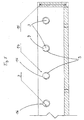
- FIG. 1 shows an example of the puzzle game according to the invention.
- the triangular Elements (1) are rotatably mounted on axes (3).
- the axes (3) are at the base (10) of a U-shaped profile (11) at the same distance and arranged parallel to each other.
- the U-shaped profile (11) is in a corresponding Recess (17) in the receptacle (18) is inserted in a form-fitting manner.
- the height of the side parts of the U-shaped profile (11), i.e. the base (10) and the legs (12) have the same height as the sides of the recess (17) of the receptacle (18).
- the elements (1) form each other parallel profiles (2) with a triangular cross-section.
- the elements (1) are on Axes (3) mounted, which are arranged coaxially within the profile (2).
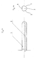
- FIG. 2 shows an enlarged representation of the area X1 from FIG. 1 this representation is a cross section through two parallel profiles (2) or Elements (1) shown with a triangular cross section, which next to the Leg (12) of the U-shaped profile (11) are arranged.
- the elements (1) are each rotatably mounted on an axis (3).
- the axis (3) points to three Sides a flattened portion (9), the flattened portions (9) at the same angle are arranged to each other.
- the elements (1) are represented by a Limit force lock (5) held in three different locking positions, wherein one element side surface (6) lies horizontally above.
- the Limit force ratchet (5) is a two-sided form lock (7) for Rotary movements.
- the double-sided mold clamp (7) is cut through an elastically deformable spring (8) is formed.
- the spring element (8) In the unstretched state the spring element (8) on one of the three flats (9) of the axis (3).
- the elastically deformable spring element (8) By turning the element (1) the elastically deformable spring element (8) deformed until it rests on the next flattening and in the Normal condition, i.e. returns to the unstretched state. All three Element side surfaces (6) are shown for the individual elements (1).
- the Locking position of the limit force lock (5) are set so that in always in the locked state one element side surface (6) horizontally above lies and forms a level with the corresponding other elements (1).
- one leg (12) of the U-shaped profile (11) is shown.
- one Fastening device (13) is shown on the end face of the legs (12) of the U-shaped profile (11).
- the U-shaped profile (11) lies in the Recess (17) of the receptacle (18) in a form-fitting manner.
- FIG. 3 shows a side view of the transition of the U-shaped profile (11) shown to the side part (14).
- the fastening devices (13) attached to the End faces of the respective legs (12) of the U-shaped profile (11) are arranged are in the corresponding openings (15) of the side part (14) positively and / or non-positively.
- the axes (3) lie with her Face in corresponding bores (16) of the side part (14). Hereby ensures that the axes (3) cannot move, i.e. it high stability is achieved. Between the two elements shown (1) a spacer ring or spacer can be introduced so that this do not rub against each other.
- Figure 4 is a plan view of the transition of the U-shaped profile (11) to the Side part (14) shown. From this figure it is clear how the fastening device (13) the leg (12) in the opening (15) of the side part (14) releasably is attached.
- the axes (3) in coaxial bores (4) within the Profiles (2) of the elements (1) are arranged with their end face in the Bores (16) of the side part (14).
- FIG. 5 shows an enlarged side view of a section of the side part (14) shown.
- the axes (3) lie in the corresponding bores (16) of the side part (14) rotatably mounted.
- the Distance between the bores (16) is the same distance that the have parallel axes (3) to each other. This ensures that the distance between the axes always remains constant.
- Figure 6 shows a leg (12), on the front side of a fastening device (13) is arranged.
- the axis (3) is parallel to the legs (12) arranged.
- Figures 7 and 14 show a side view of a portion of an axis or the cross section through an axis.
- the flats (9) are the same Angle to each other.
- FIGS. 8, 15 and 16 show cross sections through an element (1).
- Figure 8 shows the side view of an element (1) with the coaxial bore (4) and the limit force lock (5), which in this case is a two-sided Form clamp (7) in the form of an elastically deformable spring (8).
- Figures 15 and 16 is a front and rear view of an element (1). It is clear that the spring element (8) in its non-deformed position covers a segment of the coaxial bore (4).
- Figure 9 is a U-shaped profile (11) with a base (10) and two legs (12).
- a plurality of axes (3) is parallel to the legs (12) arranged on the base (10) of the U-shaped profile (11).
- the axes (3) have the same distance from each other.
- At the end faces of the legs (12) are each Fastening devices (13) arranged.
- Figure 10 shows a side part (14) with openings (15) or bores (16).
- the Openings (15) of the side part are each arranged at the end of the side part (14), so that they fix the fixtures (13) of the U-shaped Can record profiles (11).
- the axes (3) are when the Side part (14) with the U-shaped profile inserted into the bores (16).
- the Axes (3) are rotatably supported in the bores (16).
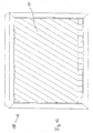
- Figure 11 shows a top view of a puzzle, i.e. through the U-shaped Profile (17) and the side part (14) attached to the U-shaped profile creates the frame of the game in a recess (17) of a receptacle (18) is positively and / or non-positively attachable.
- the three Element side surfaces (6) of the elements (1) are also shown.
- Figure 12 is a receptacle (18) with a corresponding recess (17).
- the frame through the U-shaped profile (11) and Side part (14) is formed, can be positively introduced into the recess (17) become. This gives the game a special stability.
- the receptacle (18) forms a basis for the frame.
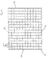
- FIG. 13 shows a puzzle game according to the invention, the horizontal one overhead pages (6) of the elements (1) are printed and as a whole result in a pattern or lettering.
- the present invention shows a mechanical device in the form of a rectangular plastic container (18) on which a number of rotating Triangular elements (1) are on axes (3). Each of the triangle elements has a coaxial bore. On the respective surfaces of the Rotary elements (1) are partial sections of a word and picture motif. By manually actuating the rotating elements (1), the individual motifs, similar to a puzzle, brought together in a certain position in which the desired overall motif can be seen as the goal of the game.
- the mechanical device is set in the examples shown in FIG. 1 to 16 from two components, the container (18) and a so-called Rotary element device, together.
- the rotary element device which from the Container (18) to be taken consists of a number of fixed axles (3), which are provided with flats (9), the adjustment or Serve snapping the rotating elements.
- the triangular elements (1) are For example, equipped with an adjusting spring (8) that is level with the Area, i.e. the flats (9), the axis (3) the adjustment mechanism or represents the limit force lock (5). This guarantees this individual rotating element (1) a correct, mutually independent Axis to get the desired position.
- That too opening side part (14) of the device shows one at each end Closure opening (15) and a number of holes on the end face or axis guides (16).
- the pictures and writings on the respective elements (1) can either can be painted or printed directly on it. It is also conceivable that the triangular elements have a magnet. So can the pictures or writings on a flat plate, which the shape of the Has element side surfaces (6), and which is also magnetic, be arranged. The plates can be easily replaced by the magnets become.
- the elements (1) on their Elementenareafietzen (6) have holding devices on or in which the respective images or writings are attached.
Landscapes
- Engineering & Computer Science (AREA)
- Multimedia (AREA)
- Toys (AREA)
- Closures For Containers (AREA)
Applications Claiming Priority (2)
| Application Number | Priority Date | Filing Date | Title |
|---|---|---|---|
| DE20003112U | 2000-02-21 | ||
| DE20003112U DE20003112U1 (de) | 2000-02-21 | 2000-02-21 | Puzzlespiel in Form eines mechanischen Gerätes mit einer Anzahl rotierender Dreieckelemente |
Publications (2)
| Publication Number | Publication Date |
|---|---|
| EP1127594A2 true EP1127594A2 (fr) | 2001-08-29 |
| EP1127594A3 EP1127594A3 (fr) | 2002-01-09 |
Family
ID=7937656
Family Applications (1)
| Application Number | Title | Priority Date | Filing Date |
|---|---|---|---|
| EP01104116A Withdrawn EP1127594A3 (fr) | 2000-02-21 | 2001-02-21 | Jeu de puzzle en forme d'un dispositif mécanique |
Country Status (2)
| Country | Link |
|---|---|
| EP (1) | EP1127594A3 (fr) |
| DE (1) | DE20003112U1 (fr) |
Family Cites Families (5)
| Publication number | Priority date | Publication date | Assignee | Title |
|---|---|---|---|---|
| US1087797A (en) * | 1913-01-08 | 1914-02-17 | Claude C Lowe | Checker-board. |
| US3410011A (en) * | 1966-07-22 | 1968-11-12 | Richard G. Bowman | Device having elements displayable in different patterns |
| US3599977A (en) * | 1969-03-17 | 1971-08-17 | Marvin Glass & Associates | Rotary block tic-tac-toe board and projectiles |
| CH533458A (fr) * | 1971-01-20 | 1973-02-15 | Anzi Vittorino | Jeu |
| US4783081A (en) * | 1986-03-05 | 1988-11-08 | Eckhardt Albert H | Playing or games board on which several games can be played |
-
2000
- 2000-02-21 DE DE20003112U patent/DE20003112U1/de not_active Expired - Lifetime
-
2001
- 2001-02-21 EP EP01104116A patent/EP1127594A3/fr not_active Withdrawn
Non-Patent Citations (1)
| Title |
|---|
| None |
Also Published As
| Publication number | Publication date |
|---|---|
| DE20003112U1 (de) | 2000-10-12 |
| EP1127594A3 (fr) | 2002-01-09 |
Similar Documents
| Publication | Publication Date | Title |
|---|---|---|
| DE69915391T3 (de) | Mechanismus zur unabhängigen Bewegung der Teile eines dreidimensionalen Gegenstandes und dessen Anwendungen | |
| DE60106083T2 (de) | Anordnung von modulen mit magnetischer verankerung zur konstruktion von stabilen gitterstrukturen | |
| DE3043764A1 (de) | Zusammenbauspielzeug | |
| DE29809820U1 (de) | Zusammensetzbarer symmetrischer Körper | |
| DE3104679C2 (de) | Zylindrisches Geduldspiel | |
| DE60320316T2 (de) | Magnetisch gesteuerte sperrvorrichtung | |
| DE3144834A1 (de) | Zauberkugel | |
| EP0722755B1 (fr) | Système de jeu de construction | |
| DE4236054C2 (de) | Mehrwürfel-Puzzlespiel | |
| DE69002264T2 (de) | Rohr oder rinne zum aufbau einer rutschbahn, eines kriechtunnels oder aehnlichem auf einem spielplatz. | |
| EP0517872A1 (fr) | Corps de transformation | |
| DE29512467U1 (de) | Steck- und aneinanderreihbares Spiel-, Lehr- oder Unterrichtsmittel | |
| EP0247045B1 (fr) | Dispositif d'indication electromagnetique | |
| DE3218072A1 (de) | Spielzeug | |
| EP1127594A2 (fr) | Jeu de puzzle en forme d'un dispositif mécanique | |
| DE3138050A1 (de) | Schiebekugel | |
| DE69926546T2 (de) | Animiertes Puzzle mit ineinander greifenden Elementen | |
| DE3601018A1 (de) | Elektromagnetische anzeigevorrichtung | |
| DE847276C (de) | Schiebespiel, bestehend aus mit Aufdrucken versehenen und in einem Aufnahmebehaelter, z. B. Rahmen, gegeneinander verschieblich angeordneten Spielsteinen | |
| DE202025103102U1 (de) | Frei kombinierbares Spielzeug | |
| DE3519187A1 (de) | Mosaiksteckspiel | |
| WO1993007942A1 (fr) | Jeu d'adresse | |
| DE3875724T2 (de) | Kombinierbare spielelemente mit spielbrett. | |
| DE3228497A1 (de) | Elemente zur bildung von zeichen | |
| DE20305120U1 (de) | Spielzeug |
Legal Events
| Date | Code | Title | Description |
|---|---|---|---|
| PUAI | Public reference made under article 153(3) epc to a published international application that has entered the european phase |
Free format text: ORIGINAL CODE: 0009012 |
|
| AK | Designated contracting states |
Kind code of ref document: A2 Designated state(s): AT BE CH CY DE DK ES FI FR GB GR IE IT LI LU MC NL PT SE TR |
|
| AX | Request for extension of the european patent |
Free format text: AL;LT;LV;MK;RO;SI |
|
| PUAL | Search report despatched |
Free format text: ORIGINAL CODE: 0009013 |
|
| AK | Designated contracting states |
Kind code of ref document: A3 Designated state(s): AT BE CH CY DE DK ES FI FR GB GR IE IT LI LU MC NL PT SE TR |
|
| AX | Request for extension of the european patent |
Free format text: AL;LT;LV;MK;RO;SI |
|
| 17P | Request for examination filed |
Effective date: 20020708 |
|
| AKX | Designation fees paid |
Free format text: AT BE CH CY DE DK ES FI FR GB GR IE IT LI LU MC NL PT SE TR |
|
| 17Q | First examination report despatched |
Effective date: 20040408 |
|
| STAA | Information on the status of an ep patent application or granted ep patent |
Free format text: STATUS: THE APPLICATION IS DEEMED TO BE WITHDRAWN |
|
| 18D | Application deemed to be withdrawn |
Effective date: 20040819 |