EP1127621A2 - Déchiqueteur, en particulier pour des supports d'information - Google Patents
Déchiqueteur, en particulier pour des supports d'information Download PDFInfo
- Publication number
- EP1127621A2 EP1127621A2 EP01103412A EP01103412A EP1127621A2 EP 1127621 A2 EP1127621 A2 EP 1127621A2 EP 01103412 A EP01103412 A EP 01103412A EP 01103412 A EP01103412 A EP 01103412A EP 1127621 A2 EP1127621 A2 EP 1127621A2
- Authority
- EP
- European Patent Office
- Prior art keywords
- cutting
- segment
- crushing device
- approx
- disks
- Prior art date
- Legal status (The legal status is an assumption and is not a legal conclusion. Google has not performed a legal analysis and makes no representation as to the accuracy of the status listed.)
- Withdrawn
Links
Images
Classifications
-
- B—PERFORMING OPERATIONS; TRANSPORTING
- B02—CRUSHING, PULVERISING, OR DISINTEGRATING; PREPARATORY TREATMENT OF GRAIN FOR MILLING
- B02C—CRUSHING, PULVERISING, OR DISINTEGRATING IN GENERAL; MILLING GRAIN
- B02C18/00—Disintegrating by knives or other cutting or tearing members which chop material into fragments
- B02C18/06—Disintegrating by knives or other cutting or tearing members which chop material into fragments with rotating knives
- B02C18/14—Disintegrating by knives or other cutting or tearing members which chop material into fragments with rotating knives within horizontal containers
- B02C18/148—Disintegrating by knives or other cutting or tearing members which chop material into fragments with rotating knives within horizontal containers specially adapted for disintegrating plastics, e.g. cinematographic films
-
- B—PERFORMING OPERATIONS; TRANSPORTING
- B02—CRUSHING, PULVERISING, OR DISINTEGRATING; PREPARATORY TREATMENT OF GRAIN FOR MILLING
- B02C—CRUSHING, PULVERISING, OR DISINTEGRATING IN GENERAL; MILLING GRAIN
- B02C18/00—Disintegrating by knives or other cutting or tearing members which chop material into fragments
- B02C18/0007—Disintegrating by knives or other cutting or tearing members which chop material into fragments specially adapted for disintegrating documents
-
- B—PERFORMING OPERATIONS; TRANSPORTING
- B02—CRUSHING, PULVERISING, OR DISINTEGRATING; PREPARATORY TREATMENT OF GRAIN FOR MILLING
- B02C—CRUSHING, PULVERISING, OR DISINTEGRATING IN GENERAL; MILLING GRAIN
- B02C18/00—Disintegrating by knives or other cutting or tearing members which chop material into fragments
- B02C18/06—Disintegrating by knives or other cutting or tearing members which chop material into fragments with rotating knives
- B02C18/14—Disintegrating by knives or other cutting or tearing members which chop material into fragments with rotating knives within horizontal containers
- B02C18/142—Disintegrating by knives or other cutting or tearing members which chop material into fragments with rotating knives within horizontal containers with two or more inter-engaging rotatable cutter assemblies
-
- B—PERFORMING OPERATIONS; TRANSPORTING
- B02—CRUSHING, PULVERISING, OR DISINTEGRATING; PREPARATORY TREATMENT OF GRAIN FOR MILLING
- B02C—CRUSHING, PULVERISING, OR DISINTEGRATING IN GENERAL; MILLING GRAIN
- B02C18/00—Disintegrating by knives or other cutting or tearing members which chop material into fragments
- B02C18/06—Disintegrating by knives or other cutting or tearing members which chop material into fragments with rotating knives
- B02C18/16—Details
- B02C18/18—Knives; Mountings thereof
- B02C18/182—Disc-shaped knives
-
- B—PERFORMING OPERATIONS; TRANSPORTING
- B02—CRUSHING, PULVERISING, OR DISINTEGRATING; PREPARATORY TREATMENT OF GRAIN FOR MILLING
- B02C—CRUSHING, PULVERISING, OR DISINTEGRATING IN GENERAL; MILLING GRAIN
- B02C18/00—Disintegrating by knives or other cutting or tearing members which chop material into fragments
- B02C18/0007—Disintegrating by knives or other cutting or tearing members which chop material into fragments specially adapted for disintegrating documents
- B02C2018/0015—Disintegrating by knives or other cutting or tearing members which chop material into fragments specially adapted for disintegrating documents for disintegrating CDs, DVDs and/or credit cards
-
- B—PERFORMING OPERATIONS; TRANSPORTING
- B02—CRUSHING, PULVERISING, OR DISINTEGRATING; PREPARATORY TREATMENT OF GRAIN FOR MILLING
- B02C—CRUSHING, PULVERISING, OR DISINTEGRATING IN GENERAL; MILLING GRAIN
- B02C18/00—Disintegrating by knives or other cutting or tearing members which chop material into fragments
- B02C18/0007—Disintegrating by knives or other cutting or tearing members which chop material into fragments specially adapted for disintegrating documents
- B02C2018/0046—Shape or construction of frames, housings or casings
Definitions
- the invention relates to a comminution device, in particular for shredding data media, according to the Preamble of claim 1.
- Such crushing devices for data or information carriers in the form of paper, foils, films, plastic layers or other flexible flat materials by cutting are also known as document shredders.
- An example is shown in DE 197 42 754.
- This shredder has a cutting unit with two in the area of a cutting passage interacting cutting rollers, each of which has a plurality of cutting disks, between which there are axial gaps into which the cutting disks of the other cutting roller for generating a cutting engagement between cutting edges of the cutting rollers.
- the intervention takes place in such a way that flat material that rotates in the opposite direction between the Cutting rollers are introduced at the respective interacting Cutting edges cut by a kind of scissors cut becomes.
- the circumference of the Cutting disc recesses may be provided between which Cutting teeth are formed. This allows the comminuted material also cut or torn in the transverse direction so that particles in the form of short strip sections arise.
- a particle cut can, for example, for reasons of confidentiality be desired because it increases security against Reproduction of documents or the like Assembling the clippings. It is also in particle form Cut material present with greater packing density to be kept as clippings with long, possibly kinked, twisted and / or crumpled strips.
- Confidential information is not just on paper To find data carriers, but also on Foils.
- thermal transfer foils which are coated with a material that is facing one transferring printing surface and there by heat is fixed. Because in the area of the removed coating no renewed printing can be carried out these foils to be printed on during the printing process Surfaces moved past and the used film material is rolled up. The rolled up, used thermal transfer foils thus carry those transferred with their help, possibly confidential information and can therefore Pose security risk.
- Data carriers for electronic media for example floppy disks or floppy disks can be deleted to Ensure confidentiality. But it may be special Methods still possible, information contained on it retrieve again. This is especially true for floppy disks, where mostly only the logical addressing is deleted, while the actual information is in the physical place their storage is retained and reproducible if necessary are. This applies to numerous types of recording on magnetic Base.
- optically writable and readable data carriers such as e.g. Compact discs (CD's)
- CD's Compact discs
- the invention is based on the object of a comminution device of the kind mentioned at the beginning to create the it allows a high level of security in a convenient manner against misuse of data in everyday office life ensure.
- a comminution device has a Cutting device that has at least two axially adjacent cutting segments has, which, in particular by different Training and / or arrangement of interacting cutting disks in the cutting segments, to destroy different ones Types of comminuted material, in particular different ones Types of data carriers are adapted.
- a cutting device In such a cutting device, they comprise at least two Cutting segments that each have a suitable width extend the cutting unit, usually several, preferably similar cutting discs, with the cutting discs different cutting segments with regard to cutting wheel width, Cutting disc distance or axial cutting disc division, Cutting disc shape and / or in the manner of Interaction with opposing cutting discs can distinguish.
- the individual cutting segments trained to be optimal for annihilation different data carrier types are designed.
- This Data carrier types generally differ significantly in terms of their dimensions and other properties, for example cutting resistance, toughness of the material, Overall structure of the data carrier or the like.
- the invention enables integration of several, on the shredding different clippings of specialized sections or segments in a cutting unit, so that one with the Cutting device equipped cutting device versatile is usable and for most, possibly also all in an office or the like Crushing capacity sufficient for safety requirements provides.
- a "multi-media shredder" possible of most of the currently common data carriers, such as Floppy disks, CD-ROMs, ZIP disks, data tape cartridges or Data cartridges, thermal transfer foils and the like. Reliable can destroy.
- At least one cutting segment is preferably provided, that for crushing, especially for cutting up flexible flat material, such as paper, foils or the like, is trained.
- a fineblanking segment be designed so that it is also Shredding of the thermal transfer films mentioned at the beginning or other thin plastic films with comparable properties is suitable.
- Such films are usually only a few tens or hundreds of micrometers thick and particularly good can be shredded with a cutter that has a small particle size generated, for example the particle width between approx. 1 and approx. 3 mm, in particular between approx. 1.5 and approx. 2.5 mm and / or particle length between approx. 10 mm and approx. 20 mm, for example approx. 15 mm.
- the fineblanking segment accept any suitable training, such as at known document shredders for paper and other flexible flat material is known.
- a data carrier unit can in particular through a disk be formed, such as in the case of a CD, or them can include a disk, for example is encased by a semi-flexible housing, as in the case from floppy disks or floppy disks.
- This slightly flexible Data carriers are usually harder or stiffer and essential thicker than paper, but not completely rigid. Typical thicknesses can range between approx. 1 mm and approx. 3.5 to 4 mm, in particular in the range between approx. 1 and 2.5 mm.
- This cutting segment for semi-rigid material can also be used to cut plastic bank cards or be used without a magnetic stripe.
- designed cutting segment have the cutting disks preferred embodiments a thickness of at least 5 mm, in particular between approx. 10 and approx. 20 mm.
- the Spaces have a corresponding, slightly larger Width, so that on each side of a cutting disc effective cutting edge is formed. This has the result Cuttings one of the cutting disc thickness essentially corresponding cutting width.
- the cutting discs on their circumference with several grooves or recesses are, for example, six in circumference.
- Preferred further developments are characterized in that at least one in the following also as a coarse cutting segment designated cutting segment is provided for comminution of essentially rigid or largely rigid Disk units is formed.
- Such disk units are preferably constructed so that the actual Disk, for example in the form of a disk or a wound film or tape can, in a largely rigid, protective housing is recorded.
- Typical examples are magnetic tape cassettes (Data cartridges) and so-called ZIP disks.
- Typical Thicknesses of such data carrier units are in the range of more than 2 mm, for example between approx. 3 and approx. 8 to 10 mm.
- Typical widths can range from approx. 4 to about 10 cm.
- an axial distance is preferably adjacent Cutting operations between cutting rollers larger than approx. 15 mm and is in particular between about 20 and about 30 mm.
- Corresponding are on the shredded material with typical Widths on the order of 10 cm or less only few cuts, for example 2, 3 or 4 cuts. This makes it possible, despite the very tough and with high cutting resistance of the shredded material with the usual engine power for the cutting unit driver Engine get along.
- the cutting disc thickness is clear is smaller than the clear width of the spaces between neighboring cutting discs, the cutting disc width preferably less than 20%, especially between 10 and Is 20% of the gap width.
- a cutting unit that is complete is designed in the manner of the coarse cutting segment, can also in a specially for the crushing of the described rigid data carrier units designed shredding device Find use.
- the other cutting segments can be omitted in this case.
- At least two different cut segments are preferred axially adjacent and usually immediately provided adjacent to each other in a cutting unit.
- a preferred embodiment in which all three are described Types of cutting segments available in a cutting unit are described in more detail using the exemplary embodiments. In particular, this embodiment can currently almost all reliably destroy conventional data carriers.
- each of the Cutting segments a separate feed opening for material to be shredded is connected upstream. This is appropriately positioned that imported shredded material only from the assigned cutting segment and not also from neighboring ones Cutting segments is detected. This allows the different Shredding capabilities of the cutting segments optimal be used.
- the feed openings are appropriate in terms of width and Height of a typical insertion profile from through the cutting segment preferably comminuted material of this type adapted that essentially only that for that particular Cutting material intended for the cutting segment is introduced can be.
- Such a mechanical insertion panel increases the operational safety of the device and is also in With regard to the disposal of comminution, if possible should be species-specific, advantageous.
- the shredding device is a controller has, which is designed such that the rotational speed and / or the torque of the cutting rollers depending on the type of material to be shredded is controllable.
- the shredding device is a controller has, which is designed such that the rotational speed and / or the torque of the cutting rollers depending on the type of material to be shredded is controllable.
- Each cutting segment is preferably on a separate feed sensor for the delivery of assigned to segment-specific feed signals and control is designed so that the rotational speed and / or the torque of the cutting rollers depending on these Feed signals are controllable. This can be achieved that for example when importing a piece of paper or a thermal transfer film automatically a higher rotation speed is set as when importing a CD into the corresponding entry slot.
- Suitable feed sensors can for example mechanically or otpoelectronically Work like a light barrier.
- the cutting unit on its material discharge side at least one preferably removable container for Shredded material assigned. Especially from the point of view material separation and subsequent recycling can the shredded material in different, separate or separate collection rooms are collected, order in this way by type or due to less different materials easily separable the material cycle be fed again.
- Creative is preferred Cutting segment a separate one and from other collecting containers separately removable receptacle assigned to insofar as independence of the various integrated To create shredding devices.
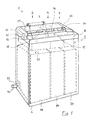
- Fig. 1 is a schematic perspective view a preferred embodiment of a comminution device 1 shown the possibility in a single device the reliable and data protection-related reduction or Destruction of different types of data media or Disk units merged.
- a first one to be seen on the left Area 2 is specifically for cutting thin Films such as thermal transfer films, paper or other flexible Flat material designed with comparable properties and creates its particles of the supplied material.
- On adjacent second area 3 is for shredding CD's, floppy disks, floppy disks or the like one-piece or multi-piece disk units, which in Compared to paper are significantly thicker, for example between 1 mm and 2 mm thick, and which are usually only moderate are flexible.
- a third region 4 which can be seen on the right, serves for cutting or shredding ZIP disks, tape cassettes (Data Cartriges) and similar data carrier units which are normally the magnetic or optical or the like.
- Protected data carriers in a largely rigid housing is housed. Typical thicknesses of this shredded material can range from a few millimeters to a centimeter lie.
- These different types of media can be used without Conversion of the shredding device can be shredded, expediently only a certain one at a given time Disk type is destroyed and the device one for its destruction optimized operating state (cutting shaft rotation speed, applied torque etc.) preferably automatically occupies. The device can also do so be set that all types of data media at the same time can be destroyed.
- the shredding device 1 has a stand in the form an open cupboard 5 with a door 6 on the visible Front. There is one on the upper cabinet opening shredding unit closing the cabinet opening upwards 7, the cutting unit indicated by dashed lines in FIG. 1 10 and a motor (Fig. 2) containing the axially parallel Cutting rollers 11, 12 via a not shown Drives gear with opposite direction of rotation synchronously.
- a feed channel 13 leads to the cutting unit the top of the feed unit with an inclined downward Feed direction is arranged (Fig. 2).
- the longitudinal slot-shaped feed opening 15 for the fine blanking area 2 a passage height of, for example about 1 mm and a passage width, which is preferred is in the range between approx. 20 and approx. 25 mm, so that for example, paper sheets in A4 format in the longitudinal direction are insertable and typical film web widths of thermal transfer films still fit through.
- An accidental Inserting CD's, floppy disks or the like is due to the narrow slot height not possible.
- the feed opening 16 assigned to the central area 3 has expediently a width that corresponds to the diameter of CD disks only slightly exceeds and for example in the range of can be about 12 cm to 13 cm, and a height of, for example about 1.5 mm, which is an import of commercially available 3.5-inch disks just barely possible, but not that Inserting ZIP disks.
- the supply opening 17 assigned to the third area 4 has in the Example a width that is larger than the edge length of a ZIP disk, but smaller than the diameter of a CD disk and for example in the range of approx. 10 cm can lie.
- the slot height is in the range between approx. 8 and approx. 15 mm and therefore also allows the insertion of Media tape cartridges. By compared to the opening 16 smaller width will result in accidental insertion of Prevents CD's or the like.
- the shredding device is in the embodiment shown a removable roll holder shown in dashed lines 21 assigned to the area outside the narrow insertion slot 15 of the fine blanking area 2 arranged and secured for example by snapping can be.
- the roll holder is used to hold Rolls of flexible flat material, such as thermal transfer foils, by means of the roll-off bracket, for example in the illustrated Way arranged above the insertion slot 15 and are rotatably mounted that the rolled flat material due to the fact that during the cutting process in the cutting unit 10 taking place continuously unrolled from the roll 21 becomes.
- the shredding device can destroy longer film webs also a suction device for active Extraction of shredded material from the area of the Cutting unit 10 or from the area of the cutting unit downstream discharge opening provided his.
- This variant is particularly useful for shredding of plastic films, where the small, light particles due to electrostatic charge tend to be in the area of the cutting unit or an ejection opening to stick and thereby block this area.
- the suction device can be, for example Channel system include that by means of a suction port 24 an external suction device, such as an industrial vacuum cleaner or a central vacuum system in an office building, can be connected.
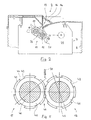
- the vertical section in Fig. 2 leads through the middle Area 3 and shows further details of the shredding unit 7. It can be seen that the upper housing part 7, the Plastic is in the direction of the inlet of the feed channel 13 drops.
- the cover 14 Before the funnel-shaped to the cutting unit tapered supply channel is the cover 14 with the Feed openings 15, 16, 17 attached, which in turn for Outside are funnel-shaped to facilitate insertion to facilitate the comminution.
- Such Coverage can be interchangeable to easily Provide feed opening with other dimensions and the Shredding device according to the needs of the Adapt the installation environment.
- the cutting unit 10 is arranged in the housing.
- the Drive motor 25 and the gearbox, which are also synchronous wheels for the oppositely synchronous drive of the cutting rollers 11, 12 of the cutting unit are only indicated.
- the two Cutting rollers 11, 12 of the cutting units 10 run parallel to each other so that they interlock with their cutting discs intervention. They are in a horizontal position inclined plane arranged with its shredding passage 26 substantially aligned with the inclined feed channel to lie. Between the cutting discs of the cutting rollers engage wipers 27, which for example consist of individual Sheet segments can exist. They include waves 11 12 by approximately 180 ° and form in particular on the inlet side protruding lugs extend the feed channel.
- the cutting rollers of the cutting unit are in the viewing direction the material feed shown.
- the cutting roller structure is exemplified with reference to the cutting roller 11 which cutting roller 12 cooperating therewith is essentially constructed identically.
- the cutting roller 11 is made in one piece hardened at least in the surface area of the cutting disks Steel made.
- Cutting shaft 32 of which is made in one piece with it Cutting discs protrude at axial distances from each other are arranged.
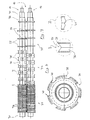
- Through different cutting wheel widths and cutting wheel spacing as well as different Formation of the cutting discs and continue through different Diameter assigned sections of the cutting shaft 32 are three different cutting segments 33, 34, 35 created, each with their constructive features optimal for shredding different clippings are designed.
- the cutting segment 33 recognizable on the left can also be used as a fine cutting segment are referred to with regard to one Particle cutting of sheet-like thin flat materials, such as Thermal transfer foils optimized and also able to handle sheets of paper to shred.
- the one assigned to the central area 3 middle cut segment 34 is specifically for shredding of CD's, flat disks and other comparable data carriers or comminuted material.
- the fine blanking segment 33 there are for example twenty seven Cutting discs 36 with a cutting disc division of approximately 4 mm, the cutting disc thickness each is slightly less than 2 mm and the intermediate ones Annular spaces are slightly wider than 2 mm, so that on both axial edges of the cutting discs reliable cutting without excessive friction ensured between the interacting cutting rollers is.
- the cutting discs have a maximum diameter of approx. 36 mm, can also be smaller or larger in diameter.
- teeth 40 are formed with tips inclined in the direction of rotation.
- the recesses and teeth of the interacting cutting disks are such around the circumference of the cutting discs distributed that in an overlap area of the cutting discs in the longitudinal direction of the cutting discs next to a groove a cutting disc of a cutting roller with a tooth the other interacting cutting disc lies.
- Typical Particle sizes are in the range of approx. 1.9 mm particle width and about 15 mm particle length.
- the middle cutting segment 34 are on a comparable axial width only five cutting discs 41 with a cutting disc division of approx. 26 mm.
- the cutting discs are slightly under with a cutting wheel width 13 mm much wider than usual, for paper destruction provided cutting discs.
- the annular spaces are dimensioned so that both axial disc surfaces the cutting disks serve as cutting edges.
- the Peripheral surfaces also have a V-shaped groove, however with a large opening angle of, for example 170 ° (detail II).
- the essentially cylindrical edge areas can be knurled again or roughened in some other way to support a safe move-in.
- Fig. 5 shows that the recesses 42 in Relative to the recesses in the fineblanking segment are flat. They are elongated in the circumferential direction and have flanks that are at an angle to the respective radial direction run.
- each recess cutting teeth 45 which in Direction of rotation of the cutting roller and on the in the direction of rotation rear flank of the recess are provided.
- the Dimensions are in the preferred embodiment shown something like this.
- the outside diameter of the cutting drum (Diameter of the cutting discs) is approx. 33 mm, the Diameter of the continuous cutting shaft section 46 about 24 mm, the groove depth about 2.5 mm.
- Axis distance between the cutting rollers grips the cutting disks 41 so that the through the bottom sections of the grooves defined circles (dash-dotted lines) in Area of the comminution passage 26 close to each other lie or just touch each other. This results in a maximum overlap (measured in the connection plane the cutting shaft axis), which is about twice the groove depth or cutting tooth height.
- the two cutting rollers through her Synchronous gearboxes are synchronized with one another in such a way that one recess each with the between two recesses lying peripheral portion of the adjacent and opposite Cutting discs coincides, this maximum overlap occurs not in practice.
- Under Consideration of the groove depth results from the mutual Engagement of the cutting discs a real overlap that is about the groove depth less, i.e. in the range of approx. 2 mm.
- the passage 49 which is between the outer circumference the cutting discs and the bottom of the annular spaces or the Outer circumference of the continuous cutting shaft section is typically a few millimeters, for example 3 to 4 mm. This distance must be much larger than with paper shredders because the material to be cut is a considerable one Can have thickness. For example, the thickness is a CD disk approx. 1.2 mm and that of a floppy disk with its Floppy disk housing approx. 2 mm.
- the relatively small real overlap is enough for the relatively thick and hard materials of the disk unit 50 to shred them.
- the cutting disc thickness is significantly smaller than their axial distance and for example only 10% to 20% this annulus width is.
- the cutting disc thickness can for example, only about 3 mm, the axial distance on the other hand, for example, 28 mm to 30 mm.
- the cutting disks act opposite Cutting rollers only on one side to produce one Cutting intervention together so that the three generated Cutting lines in this area one of the cutting disc division have the appropriate distance, in the example approx. 30 mm is. This large distance is sufficient to be relative to shred hard, supplied materials so far that it is impossible to reproduce the data media it contains.
- the cutting disks 55 also have a circumference Recesses 56 that are oblique to the longitudinal direction of the shaft are offset from each other and essentially serve to hook into the supplied material and thereby the Effect.
- each of the insertion slots 15, 16, 17 have their own feed sensor, for example according to Allocate a type of light barrier to that of a device control emits a feed signal, which is evaluated by the controller and to control the motor with different Rotational speeds is used. For example when inserting a sheet of paper into the slot 15 of the appropriate feed sensor are activated, whereupon the Motor a high cutting shaft speed at comparatively low torque sets to as quickly as possible to be able to cut a lot of thin flat material.
- Cutting paper or foils can in itself known manner at a relatively high cutting roller speed respectively.
- the material removal can be suction can be selectively switched on and off.
- a CD disc is stationary Cutting device inserted in the middle insertion slot 16, see above the motor is attached via the feed sensor attached there an average rotational speed started, the is smaller than when cutting foils, paper or the like Cutting rollers turn in opposite directions and pull the CD in the passage 49 a.
- the CD is on the one hand by the roughened peripheral edges and on the other hand from the teeth gripped and pulled safely into the cutting unit in which a particle cut takes place.
- the teeth dig into it Material, pierce it and after that, along the A longitudinal cut is made to the side edges of the cutting disks.
- the number and dimensions of the recesses make the Particle length, and due to the width of the cutting disc Particle width set. The particles run during the Cut through the passage 49 and then fall in the collecting container 19.
- Feed opening 17 automatically becomes an even lower one Cutting shaft rotation speed and a correspondingly higher Torque set.
- the data carrier unit is also here clawed by the teeth on the circumference of the cutting disks 55 and moved in.
- the material is along two to three lines with a relatively high line spacing of, for example, approx. 30 cm severed and, if necessary, also torn across.
- cutting segments there are only two different cutting segments are provided, for example only one fine blanking segment and one blanking segment according to Art of segment 34 for floppy disks or the like or a combination consisting of fine-cutting segment and cutting segment for ZIP disks in the manner of cutting segment 35.
- Cutting segments there are also four or more Cutting segments possible, for example separate segments for thermal transfer foils, CD's, diskettes and ZIP's. This can with regard to the separation of materials for recycling be beneficial.
Landscapes
- Engineering & Computer Science (AREA)
- Food Science & Technology (AREA)
- Crushing And Pulverization Processes (AREA)
Applications Claiming Priority (2)
| Application Number | Priority Date | Filing Date | Title |
|---|---|---|---|
| DE2000108442 DE10008442A1 (de) | 2000-02-23 | 2000-02-23 | Zerkleinerungsvorrichtung, insbesondere zur Zerkleinerung von Datenträgern |
| DE10008442 | 2000-02-23 |
Publications (2)
| Publication Number | Publication Date |
|---|---|
| EP1127621A2 true EP1127621A2 (fr) | 2001-08-29 |
| EP1127621A3 EP1127621A3 (fr) | 2002-12-18 |
Family
ID=7632105
Family Applications (1)
| Application Number | Title | Priority Date | Filing Date |
|---|---|---|---|
| EP01103412A Withdrawn EP1127621A3 (fr) | 2000-02-23 | 2001-02-14 | Déchiqueteur, en particulier pour des supports d'information |
Country Status (2)
| Country | Link |
|---|---|
| EP (1) | EP1127621A3 (fr) |
| DE (1) | DE10008442A1 (fr) |
Cited By (10)
| Publication number | Priority date | Publication date | Assignee | Title |
|---|---|---|---|---|
| WO2003033153A1 (fr) * | 2001-10-11 | 2003-04-24 | Dahle Bürotechnik Gmbh | Destructeur de documents a coupe transversale |
| EP1449589A1 (fr) * | 2003-02-18 | 2004-08-25 | Frank Chang | Déchiqueteur de documents à usages multiples |
| USRE40042E1 (en) | 2000-10-10 | 2008-02-05 | Michilin Prosperity Co., Ltd. | Dual-functional medium shredding machine structure |
| WO2008025551A1 (fr) * | 2006-08-30 | 2008-03-06 | Hsm Gmbh + Co. Kg | Déchiqueteuse de documents multifonction |
| US7398936B1 (en) | 2007-01-05 | 2008-07-15 | Michilin Prosperity Co., Ltd. | Top and side loading shredder with optional handle |
| WO2009012942A1 (fr) * | 2007-07-23 | 2009-01-29 | Hermann Schwelling | Dispositif pour déchiqueter des supports de données |
| WO2009010712A3 (fr) * | 2007-07-13 | 2009-04-23 | Sean Thomas Hallard | Appareil, système et procédé pour déchiqueter des plaques de plâtre |
| WO2009065290A1 (fr) * | 2007-11-20 | 2009-05-28 | Guangzhou Sunny Comet Electronics Science And Technology Co., Ltd. | Ensemble de rouleaux d'entraînement à double usage et déchiqueteuse à papier multifonction |
| US7874506B2 (en) | 2007-01-05 | 2011-01-25 | Michilin Prosperity Co., Ltd. | Top and side loading shredder with optional handle |
| WO2023062546A1 (fr) * | 2021-10-11 | 2023-04-20 | Odwyer Brendan | Déchiqueteur rotatif |
Families Citing this family (7)
| Publication number | Priority date | Publication date | Assignee | Title |
|---|---|---|---|---|
| DE10058082C2 (de) * | 2000-11-23 | 2002-11-14 | Mewa Recycling Maschinen Und A | Verfahren zur Wiederherrichtung eines Scheibensatzes einer Zerkleinerungseinrichtung und Scheibensaz hierfür |
| DE10229684A1 (de) * | 2002-06-26 | 2004-01-22 | Schleicher & Co International Ag | Dokumentenvernichter, insbesondere für eine Absauganlage |
| DE10229685A1 (de) * | 2002-06-26 | 2004-01-22 | Schleicher & Co International Ag | Dokumentenvernichter, insbesondere für eine Absauganlage |
| DE10253661A1 (de) * | 2002-11-18 | 2004-05-27 | Primax Electronics Ltd. | Zerkleinerungsvorrichtung |
| DE10353188B4 (de) * | 2003-11-13 | 2020-01-30 | Hermann Schwelling | Vorrichtung zum Zerkleinern leerer Behälter |
| DE102016200756A1 (de) | 2016-01-20 | 2017-07-20 | intimus International GmbH | Zerkleinerungsvorrichtung und Verfahren zum Betrieb einer solchen Zerkleinerungsvorrichtung |
| DE102020102310A1 (de) | 2020-01-30 | 2021-08-05 | Leonhard Kurz Stiftung & Co. Kg | Verfahren zum Recyclen eines Transferprodukts |
Citations (1)
| Publication number | Priority date | Publication date | Assignee | Title |
|---|---|---|---|---|
| DE19742754A1 (de) | 1997-09-27 | 1999-04-01 | Schleicher & Co Int | Schneidwerk für einen Dokumentenvernichter |
Family Cites Families (6)
| Publication number | Priority date | Publication date | Assignee | Title |
|---|---|---|---|---|
| DE2516111C2 (de) * | 1975-04-12 | 1984-05-17 | Adolf 7460 Balingen Ehinger jun. | Zerkleinerungsvorrichtung, insbesondere zur Verarbeitung von Papier und Kunststoffmaterial |
| DE7712423U1 (de) * | 1977-04-20 | 1978-04-06 | Wigand, Gerhard, 7140 Ludwigsburg | Geraet zum vernichten von mikrofilmen u.dgl. |
| DE3112667C2 (de) * | 1981-03-31 | 1987-04-30 | Feinwerktechnik Schleicher & Co, 7778 Markdorf | Aktenvernichtungsgerät |
| JPH09206616A (ja) * | 1996-02-07 | 1997-08-12 | Tatsuhiro Narimoto | 廃棄物の分別破砕装置 |
| DE19912036A1 (de) * | 1999-03-17 | 2000-09-21 | Schleicher & Co Int | Zerkleinerungsvorrichtung für Datenträgerscheiben und Entsorgungssystem dafür |
| JP2002001149A (ja) * | 2000-06-26 | 2002-01-08 | Rikio Yamashita | 2室2軸式破砕機 |
-
2000
- 2000-02-23 DE DE2000108442 patent/DE10008442A1/de not_active Withdrawn
-
2001
- 2001-02-14 EP EP01103412A patent/EP1127621A3/fr not_active Withdrawn
Patent Citations (1)
| Publication number | Priority date | Publication date | Assignee | Title |
|---|---|---|---|---|
| DE19742754A1 (de) | 1997-09-27 | 1999-04-01 | Schleicher & Co Int | Schneidwerk für einen Dokumentenvernichter |
Cited By (12)
| Publication number | Priority date | Publication date | Assignee | Title |
|---|---|---|---|---|
| USRE40042E1 (en) | 2000-10-10 | 2008-02-05 | Michilin Prosperity Co., Ltd. | Dual-functional medium shredding machine structure |
| USRE44865E1 (en) | 2000-10-10 | 2014-04-29 | Michilin Prosperity Co., Ltd. | Dual functional medium shredding machine structure |
| WO2003033153A1 (fr) * | 2001-10-11 | 2003-04-24 | Dahle Bürotechnik Gmbh | Destructeur de documents a coupe transversale |
| EP1449589A1 (fr) * | 2003-02-18 | 2004-08-25 | Frank Chang | Déchiqueteur de documents à usages multiples |
| WO2008025551A1 (fr) * | 2006-08-30 | 2008-03-06 | Hsm Gmbh + Co. Kg | Déchiqueteuse de documents multifonction |
| US7398936B1 (en) | 2007-01-05 | 2008-07-15 | Michilin Prosperity Co., Ltd. | Top and side loading shredder with optional handle |
| US7874506B2 (en) | 2007-01-05 | 2011-01-25 | Michilin Prosperity Co., Ltd. | Top and side loading shredder with optional handle |
| WO2009010712A3 (fr) * | 2007-07-13 | 2009-04-23 | Sean Thomas Hallard | Appareil, système et procédé pour déchiqueter des plaques de plâtre |
| WO2009012942A1 (fr) * | 2007-07-23 | 2009-01-29 | Hermann Schwelling | Dispositif pour déchiqueter des supports de données |
| DE102007034224A1 (de) | 2007-07-23 | 2009-01-29 | Hermann Schwelling | Vorrichtung für die Zerkleinerung von Datenträgern |
| WO2009065290A1 (fr) * | 2007-11-20 | 2009-05-28 | Guangzhou Sunny Comet Electronics Science And Technology Co., Ltd. | Ensemble de rouleaux d'entraînement à double usage et déchiqueteuse à papier multifonction |
| WO2023062546A1 (fr) * | 2021-10-11 | 2023-04-20 | Odwyer Brendan | Déchiqueteur rotatif |
Also Published As
| Publication number | Publication date |
|---|---|
| DE10008442A1 (de) | 2001-08-30 |
| EP1127621A3 (fr) | 2002-12-18 |
Similar Documents
| Publication | Publication Date | Title |
|---|---|---|
| EP1127621A2 (fr) | Déchiqueteur, en particulier pour des supports d'information | |
| EP0184786B2 (fr) | Dispositif de destruction de billets de banque | |
| EP2012926B1 (fr) | Unite de compactage de corps creux | |
| DE202007010399U1 (de) | Schneidklinge und drehende Schneidanordnung für Schredder | |
| EP0090248B1 (fr) | Dispositif de déchiquetage de documents | |
| DE202010001577U1 (de) | Aktenvernichter | |
| EP0447854B1 (fr) | Dispositif de coupe pour destructeur de documents | |
| DE3540896A1 (de) | Zerkleinerungsvorrichtung | |
| DE2256267B2 (de) | Mit Scherwirkung arbeitender Zerkleinerer | |
| DE3312173C2 (de) | Schneidwerk einer zum Zerkleinern und Vernichten von Papierbögen, Dokumenten und Folien dienenden Vorrichtung | |
| DE3234485A1 (de) | Zerkleinerungsvorrichtung fuer abfall | |
| EP1036595B1 (fr) | Dispositif de destruction de disques supports de données et système de récupération pour ceux-ci | |
| CH706726A2 (de) | Gerät zum Bearbeiten von Lebensmitteln. | |
| EP3195934B1 (fr) | Dispositif de broyage et procédé de fonctionnement d'un tel dispositif de broyage | |
| DE3406285C2 (fr) | ||
| EP2759346B1 (fr) | Broyeur | |
| EP1351871B1 (fr) | Dispositif d'emission destine a emettre des feuilles individuelles | |
| DE19742754C2 (de) | Schneidwerk für einen Dokumentenvernichter mit unterschiedlichen Schneidscheibenteilungen | |
| DE3607503A1 (de) | Vorrichtung zum zerkleinern von baendern | |
| DE3329339C2 (fr) | ||
| DE4025631A1 (de) | Aktenwolf | |
| DE2526109C3 (de) | Schneidwerk einer Vorrichtung zum Vernichten von blattförmigem Material | |
| DE3503519A1 (de) | Geraet zum zerkleinern von informationstraegern, insbesondere auch von farbbandkassetten | |
| DE10150026A1 (de) | Dokumentenvernichter für den crosscut-Schnitt | |
| DE9000763U1 (de) | Vorrichtung zum Zerkleinern von flächigem Zerkleinerungsgut in einzelne Partikel |
Legal Events
| Date | Code | Title | Description |
|---|---|---|---|
| PUAI | Public reference made under article 153(3) epc to a published international application that has entered the european phase |
Free format text: ORIGINAL CODE: 0009012 |
|
| AK | Designated contracting states |
Kind code of ref document: A2 Designated state(s): AT BE CH CY DE DK ES FI FR GB GR IE IT LI LU MC NL PT SE TR |
|
| AX | Request for extension of the european patent |
Free format text: AL;LT;LV;MK;RO;SI |
|
| PUAL | Search report despatched |
Free format text: ORIGINAL CODE: 0009013 |
|
| AK | Designated contracting states |
Kind code of ref document: A3 Designated state(s): AT BE CH CY DE DK ES FI FR GB GR IE IT LI LU MC NL PT SE TR |
|
| AX | Request for extension of the european patent |
Free format text: AL;LT;LV;MK;RO;SI |
|
| 17P | Request for examination filed |
Effective date: 20030215 |
|
| AKX | Designation fees paid |
Designated state(s): AT BE CH CY DE DK ES FI FR GB GR IE IT LI LU MC NL PT SE TR |
|
| AXX | Extension fees paid |
Extension state: LV Payment date: 20030215 Extension state: RO Payment date: 20030215 Extension state: LT Payment date: 20030215 Extension state: SI Payment date: 20030215 |
|
| 17Q | First examination report despatched |
Effective date: 20040723 |
|
| STAA | Information on the status of an ep patent application or granted ep patent |
Free format text: STATUS: THE APPLICATION IS DEEMED TO BE WITHDRAWN |
|
| 18D | Application deemed to be withdrawn |
Effective date: 20041203 |