EP1127624A1 - Pumpe mit einer als Feder wirkenden Membrane and Behälter mit einer solchen Pumpe - Google Patents
Pumpe mit einer als Feder wirkenden Membrane and Behälter mit einer solchen Pumpe Download PDFInfo
- Publication number
- EP1127624A1 EP1127624A1 EP01400455A EP01400455A EP1127624A1 EP 1127624 A1 EP1127624 A1 EP 1127624A1 EP 01400455 A EP01400455 A EP 01400455A EP 01400455 A EP01400455 A EP 01400455A EP 1127624 A1 EP1127624 A1 EP 1127624A1
- Authority
- EP
- European Patent Office
- Prior art keywords
- membrane
- pump
- pump according
- relative
- pumping chamber
- Prior art date
- Legal status (The legal status is an assumption and is not a legal conclusion. Google has not performed a legal analysis and makes no representation as to the accuracy of the status listed.)
- Granted
Links
Images

Classifications
-
- B—PERFORMING OPERATIONS; TRANSPORTING
- B05—SPRAYING OR ATOMISING IN GENERAL; APPLYING FLUENT MATERIALS TO SURFACES, IN GENERAL
- B05B—SPRAYING APPARATUS; ATOMISING APPARATUS; NOZZLES
- B05B11/00—Single-unit hand-held apparatus in which flow of contents is produced by the muscular force of the operator at the moment of use
- B05B11/01—Single-unit hand-held apparatus in which flow of contents is produced by the muscular force of the operator at the moment of use characterised by the means producing the flow
- B05B11/10—Pump arrangements for transferring the contents from the container to a pump chamber by a sucking effect and forcing the contents out through the dispensing nozzle
- B05B11/1001—Piston pumps
-
- B—PERFORMING OPERATIONS; TRANSPORTING
- B05—SPRAYING OR ATOMISING IN GENERAL; APPLYING FLUENT MATERIALS TO SURFACES, IN GENERAL
- B05B—SPRAYING APPARATUS; ATOMISING APPARATUS; NOZZLES
- B05B11/00—Single-unit hand-held apparatus in which flow of contents is produced by the muscular force of the operator at the moment of use
- B05B11/01—Single-unit hand-held apparatus in which flow of contents is produced by the muscular force of the operator at the moment of use characterised by the means producing the flow
- B05B11/10—Pump arrangements for transferring the contents from the container to a pump chamber by a sucking effect and forcing the contents out through the dispensing nozzle
- B05B11/1042—Components or details
- B05B11/1052—Actuation means
- B05B11/1053—Actuation means combined with means, other than pressure, for automatically opening a valve during actuation; combined with means for automatically removing closures or covers from the discharge nozzle during actuation
-
- B—PERFORMING OPERATIONS; TRANSPORTING
- B05—SPRAYING OR ATOMISING IN GENERAL; APPLYING FLUENT MATERIALS TO SURFACES, IN GENERAL
- B05B—SPRAYING APPARATUS; ATOMISING APPARATUS; NOZZLES
- B05B11/00—Single-unit hand-held apparatus in which flow of contents is produced by the muscular force of the operator at the moment of use
- B05B11/01—Single-unit hand-held apparatus in which flow of contents is produced by the muscular force of the operator at the moment of use characterised by the means producing the flow
- B05B11/10—Pump arrangements for transferring the contents from the container to a pump chamber by a sucking effect and forcing the contents out through the dispensing nozzle
- B05B11/1042—Components or details
- B05B11/1073—Springs
- B05B11/1076—Traction springs, e.g. stretchable sleeve
Definitions
- the present invention relates to a pump for dispensing a product, especially cosmetic.
- a membrane made of an elastomer is mounted on the support.
- This membrane has a symmetrical central part of revolution, in sleeve shape open at its upper end and closed at its lower end.
- the central conduit of the push button is inserted into the membrane until lean against the bottom of the central part in the form of a sleeve.
- the membrane constitutes an elastic return member making it possible to bring the push button in its initial position after dispensing a dose of product.
- the membrane by sticking to the central duct isolates the pumping chamber and avoids a re-entry of air into it.
- the membrane thus plays the role of a discharge valve.
- the membrane plays also the role of a suction valve.
- Such a pump has the advantage of having only a small number of parts and therefore to be relatively inexpensive to manufacture.
- the present invention aims to improve the reliability of the operation of a pump of the type defined above, namely comprising a support assembly, with subject to a container containing a product to be distributed, a movable member defining with the support assembly a pumping chamber of variable volume and a elastically deformable membrane, secured to one of the support assembly and of the movable member, this membrane being arranged to deform elastically when the movable member is moved relative to the support, the pump comprising in addition to an element forming a suction valve, arranged to oppose the return of product in the container when the volume of the pumping chamber decreases and an element forming a discharge valve, arranged to oppose an entry of air into the container when the volume of the pumping chamber increases.
- the pump according to the invention is characterized in that the element forming discharge valve is produced by means of a shutter element separate from the diaphragm and the fact that the diaphragm is prestressed when the pump is at rest.
- the membrane can play the role of a spring without there have to fear a blockage of the movable member; the discharge valve member being distinct from the membrane, the latter is not likely to oppose the departure of the product leaving the pumping chamber.
- the membrane being prestressed when the pump is at rest, we avoids any backlash and reduces the risk of product leakage when transporting the pump.
- the membrane has a central part in sleeve shape open at one end and closed at the opposite end, central part against which the movable member bears.
- the movable member that is to say by example the push button, has first and second movable parts one with respect to the other, the first part defining with the assembly forming a support the pumping chamber of variable volume, the second part being movable relative at the first part enters on the one hand a relative distribution position in which it is able to train the first part in the direction of a decrease in the volume of the pumping chamber and on the other hand a relative suction position in which it is able to train the first part in the direction of an increase in the volume of the pumping chamber, the shutter element belonging to the second part, the first part comprising a passage for the circulation of the product towards a nozzle for distribution, the shutter element being movable relative to the first part between a relative shutter position in which it closes said passage and a relative distribution position in which it ceases to close said passage.
- the shutter element is in its relative shutter position when the second part of the movable member is in its relative suction position and the shutter member is in its relative position distribution when the second part of the movable member is in its position relative distribution.
- the shutter member bears on the membrane.
- the element forming a shutter advantageously bears against the bottom of this central part.
- the aforementioned passage is advantageously defined by a chimney engaged at inside this central part.
- the shutter element advantageously comprises a rod fixed at one end to the second part of the movable member, this rod extending to the interior of the aforementioned chimney and being provided at the opposite end with a part forming a needle, capable of being applied in a sealed manner on the chimney to close it.
- At least one of the first and second parts of the movable member comprises a sealing lip capable of being applied so waterproof on the other part during the relative displacement of the two parts.
- this sealing lip is formed on the first part, at a end of the aforementioned passage.
- the first part of the movable member is snapped into the support assembly.
- This first part advantageously corresponds to the lower part of a push button comprising two telescopic parts.
- the support assembly comprises a insert on which the membrane is mounted.
- the membrane has a part peripheral defining a groove used for its mounting on the insert.
- the insert includes a suction valve made in one piece by plastic molding.
- the peripheral part of the membrane has a flexible lip forming a suction valve, the support assembly comprising one or more openings allowing the product to reach the pumping chamber when the volume of it increases, this or these openings being closed by the flexible lip when the volume of the pumping chamber decreases.
- the invention also relates to a container equipped with a pump such as defined above.
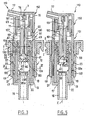
- FIGS. 1 and 2 show a pump 10 intended to be mounted on a container R of which only the upper end of the neck 1 has been shown in the figures, provided with an annular bead 2.
- the pump 10 comprises a static assembly 11 comprising a support 12 and an insert 30.
- the support 12 comprises a tubular skirt 12a of axis X, provided at its upper end of a rim 13, the latter being directed radially outwards.
- the tubular skirt 12a is applied by its radially outer surface 14, so sealed on the radially inner surface of the neck 1 of the container R.
- the rim 13 is extended radially outwards, at several points of its periphery, by mounting lugs 15 arranged to snap onto the bead ring finger 2.
- the tubular skirt 12a is connected at its lower end, by a wall transverse 20, to a nozzle 16 intended for connection to a non-immersed tube shown, to allow use of the container R head up.
- the end piece 16 is extended upwards inside the support 12 by a conduit 17.
- the tubular skirt 12a has in the lower part a recess 18 towards the interior, which is connected to a cylindrical wall 19 of axis X used for mounting insert 30.
- the cylindrical wall 19 is connected below the transverse wall 20 cited above.
- the support 12 is crossed, at the level of the step 18, by an orifice 21 intended to allow air to enter the container R, as will be specified by the after.
- tubular skirt 12a has, substantially at mid-height, a annular groove 22 formed on its radially inner surface.
- This groove 22 is delimited below by an annular bead 23 and above by a shoulder 24, which is located at the lower end of a ramp 25 inclined inwards and downwards.
- the insert 30 comprises a tubular wall 31, of axis X, forcibly engaged at its lower end in the cylindrical wall 19.
- the tubular wall 31 divides in two, at its upper end, to form on the one hand on the radially outer side a sealing lip 32 and on the other hand on the side radially inside an extension 33, which is crossed in several locations of its periphery by openings 34 whose function will be explained later.
- Longitudinal channels 35 are formed on the radially inner surface from the tubular wall 31 to the openings 34.
- the extension 33 serves for the attachment of a membrane 40 produced in a elastomeric material, for example a nitrile or silicone elastomer.
- This membrane 40 has a central part in the form of a sleeve 41 and a flexible annular lip 42 at its upper part, this annular lip 42 surrounding the central part in the form of a sleeve 41 and connecting to the upper end of this by a transverse wall 43 bearing on the end edge upper of the above extension 33.
- the central part of the membrane 40 is closed by a bottom 45.
- the height of the annular lip 42 is greater than that of the openings 34 and the annular lip 42 is arranged to be applied, at rest, in a sealed manner on the radially outer surface of the extension 33, so as to be able to prevent a return of product to container R through the openings 34, as will be explained further.
- the pump 10 comprises, in addition to the static assembly 11 which has just been described, a movable assembly forming push button 50, comprising a lower part 51 partially engaged in the support 12 and a movable upper part 52 relative to the lower part 51.
- the lower part 51 includes a mounting skirt 53 arranged to snap into support 12.
- This mounting skirt 53 has a radially inner surface 54 cylindrical of revolution around the X axis, to which is applied in a sealed manner the annular sealing lip 32 of the insert 30.
- the mounting skirt 53 further comprises, on its surface radially exterior, teeth 56 arranged to snap into the annular groove 22 of the support 12.
- the lower end 57 of the mounting skirt 53 has a lip annular arranged to apply sealingly on the annular boss 23 when the teeth 56 rest against the shoulder 24, as shown in FIG. 1.
- the lower part 51 has, above the mounting skirt 53, a col 60.
- This neck 60 has, on its radially outer surface, a groove annular 61 which is used for hooking the upper part 52 of the push button.
- the upper part 52 comprises a mounting skirt 63 provided at its lower end of an annular bead 64 arranged to snap into the groove 61 cited above.
- the neck 60 forms with the mounting skirt 53 a shoulder 65 on which the upper part 52 can be supported.
- the lower part 51 has a transverse wall 66 which is connected to the inner surface of the neck 60 above the annular groove 61.
- This transverse wall 66 supports an annular lip 67 directed downwards and an annular lip 68 directed upwards, the functions of which will be specified more far.
- the upper part 52 has an inner skirt 70 whose surface radially inner has a shoulder 73 at its lower end, this shoulder 73 axially delimiting a cylindrical surface 71 of revolution, on which applies sealingly the annular lip 68 at its upper end.
- a cylindrical housing 74 is produced in the center of the inner skirt 70 for receiving a shutter member 80 which will be described later.
- the upper part 52 includes a dispensing tip 77 communicating with the space defined by the inner skirt 70.
- the annular lips 67 and 68 define a passage 90 allowing the product from the container to the dispensing tip 77.
- the shutter member 80 has a rod 81 in the upper part. fixed in the housing 74 and, in the lower part, an internally recessed part 82 is connecting to the rod 81 by forming a shoulder 83.
- This shoulder 83 is designed to bear against the lower end of the annular lip 67 when the pump is at rest, as shown in FIG. 1.
- the shutter member 80 then rests at its lower end 86 against the bottom 45 of the central part 41 of the membrane 40.
- the lower part 51 defines, with the membrane 40 and the element forming shutter 80, a pumping chamber of variable volume 91.
- the passage 90 is closed by the element forming a shutter 80 and the lower part 51 abuts by the teeth 56 against the shoulder 24 under the biasing action of the membrane 40.
- the upper part 52 then causes the part to move downward. lower 51.
- the downward movement of the lower part 51 results in a reduction of the volume of the pumping chamber 91 and the product outlet via the dispensing nozzle 77.
- the flexible lip 42 is pressed under the effect of the pressure of the product against the radially outer surface of the extension 33 when the volume of the pumping decreases, and thus prevents the return of product to the container R.
- the element forming shutter 80 presses on the bottom 45 of the membrane 40 and causes deformation elastic of its central part 41.
- the membrane 40 behaves like a spring and gives the pump 10 pleasant behavior for the user.
- the element forming shutter 80 is brought by the membrane 40 in abutment against the annular lip 67, this which closes the passage 90, then the lower part 51 is brought upwards, which has as a consequence of increasing the volume of the pumping chamber 91 and causing a product suction therein, the flexible lip 42 moving away from the insert 30 to allow the product to circulate through the openings 34.
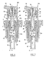
- FIGS. 3 to 5 show a pump 110 conforming to a first variant implementation of the invention.
- the pump 110 shown in Figures 3 to 5 differs from the pump 10 previously described essentially by the shape of the shutter element, that of the lower part of the push button and by the presence of a suction valve independent of the membrane.
- the static assembly 11 of the pump 10 is replaced in this example by a static assembly 111 comprising an insert 130 which differs from the insert 30 previously described by the presence of a valve 95 made in one piece by molding of material plastic with insert 130.
- the body 95a of the valve 95 is connected to the insert 130 by flexible connections 96 which allow a certain mobility along the X axis.
- the lower part 51 of the push button 50 of the previous embodiment is replaced by a part lower 151 which differs from it by the fact that the lower annular lip 67 is replaced by a chimney 167 which extends inside the central part of the membrane 40 and defines a passage 190 for the product.
- the upper part 152 includes a shutter element 180 which comprises a rod 181 fixed at one end in the housing 74, this rod 181 being provided at the other end with a needle element 183 having a surface frustoconical 183a converging upwards.
- the lower end of the chimney 167 is shaped to apply from sealingly on this frustoconical surface 183a when the pump 110 is at rest, that is to say in the configuration shown in FIG. 3.
- the needle-shaped part 183 rests permanently against the bottom 45 of the membrane 40.
- the insert 130 differs from the insert 30 previously described in that the extension 33 is replaced by an extension 133 provided with openings 134 which extend over a height greater than that of the flexible lip 42 of the membrane 40.
- the flexible lip 42 simply has, in the embodiment of the Figures 3 to 5, an attachment function, and no longer an additional function of suction valve as was the case in the embodiment of Figures 1 and 2.
- the operation of the pump 110 is as follows.
- the lower end of the mounting skirt 63 comes at the end of a stroke predetermined pressing on the lower part 151.
- the body 95a of the valve 95 being pressed against its seat constituted by the upper end of the conduit 17 prevents the product from returning to the container.
- the membrane 40 begins by bringing the shutter element 180 in abutment against the end bottom of the chimney 167 to close the passage 190.
- the upper part 152 is then driven in upward movement by the membrane 40, which tends to return to its initial shape.
- the volume of the pumping chamber 191 increases and there is a suction of product from container R.
- the product flows through the conduit 17, the body 95a of the valve 95 deviating from the upper end of the duct 17.
- the lower part 151 of the push button of the previous embodiment is replaced by the lower part 51 previously described.
Landscapes
- Reciprocating Pumps (AREA)
- Closures For Containers (AREA)
- Containers And Packaging Bodies Having A Special Means To Remove Contents (AREA)
Applications Claiming Priority (2)
| Application Number | Priority Date | Filing Date | Title |
|---|---|---|---|
| FR0002242A FR2805183B1 (fr) | 2000-02-23 | 2000-02-23 | Pompe comportant une membrane formant ressort et recipient ainsi equipe |
| FR0002242 | 2000-02-23 |
Publications (2)
| Publication Number | Publication Date |
|---|---|
| EP1127624A1 true EP1127624A1 (de) | 2001-08-29 |
| EP1127624B1 EP1127624B1 (de) | 2008-10-01 |
Family
ID=8847296
Family Applications (1)
| Application Number | Title | Priority Date | Filing Date |
|---|---|---|---|
| EP01400455A Expired - Lifetime EP1127624B1 (de) | 2000-02-23 | 2001-02-21 | Pumpe mit einer als Feder wirkenden Membrane and Behälter mit einer solchen Pumpe |
Country Status (8)
| Country | Link |
|---|---|
| US (1) | US6520385B2 (de) |
| EP (1) | EP1127624B1 (de) |
| JP (1) | JP3510862B2 (de) |
| AT (1) | ATE409526T1 (de) |
| CA (1) | CA2337542C (de) |
| DE (1) | DE60135938D1 (de) |
| ES (1) | ES2313934T3 (de) |
| FR (1) | FR2805183B1 (de) |
Cited By (2)
| Publication number | Priority date | Publication date | Assignee | Title |
|---|---|---|---|---|
| FR2885887A1 (fr) * | 2005-05-20 | 2006-11-24 | Rexam Dispensing Systems Sas | Pompe a pointeau pour la distribution de produit liquide |
| FR2918421A1 (fr) * | 2007-07-02 | 2009-01-09 | Oreal | Pompe a membrane adaptable a tous types de recipients et recipient pourvu d'une telle pompe |
Families Citing this family (12)
| Publication number | Priority date | Publication date | Assignee | Title |
|---|---|---|---|---|
| FR2852302B1 (fr) * | 2003-03-13 | 2006-07-14 | Valois Sas | Organe de distribution de produit fluide et distributeur de produit fluide comprenant un tel organe |
| US20040222243A1 (en) * | 2003-05-08 | 2004-11-11 | Saint-Gobain Calmar Inc. | Low-cost, in-line trigger operated pump sprayer |
| FR2885890B1 (fr) * | 2005-05-20 | 2007-07-20 | Rexam Dispensing Systems Sas | Dispositif pour la delivrance et l'admission d'un produit liquide |
| DE102008024181B4 (de) | 2008-05-19 | 2016-03-03 | Megaplast Gmbh & Co. Kg | Spender |
| US8622254B2 (en) * | 2009-01-14 | 2014-01-07 | Sungil Kang | Dispensing pump with resilient biasing member |
| US10473176B2 (en) * | 2018-01-03 | 2019-11-12 | Silgan Dispensing Systems Corporation | Compression spring assembly and methods of using the same |
| US10794445B2 (en) | 2018-01-03 | 2020-10-06 | Silgan Dispensing Systems Corporation | Dispensing pump with polymer compression spring assembly |
| US11236794B2 (en) | 2018-01-03 | 2022-02-01 | Silgan Dispensing Systems Corporation | Dispensing pump with polymer spring, base venting and flow baffle |
| US11035429B2 (en) | 2018-01-03 | 2021-06-15 | Silgan Dispensing Systems Corporation | Compression spring assembly and methods of using the same |
| US10870123B2 (en) | 2018-01-03 | 2020-12-22 | Silgan Dispensing Systems Corporation | Dispensing pump with locking structures and methods of using the same |
| US11312613B2 (en) | 2018-09-27 | 2022-04-26 | Silgan Dispensing Systems Corporation | Dispensing tap and methods for using the same |
| US10526191B1 (en) | 2018-09-27 | 2020-01-07 | Silgan Dispensing Systems Corporation | Dispensing tap and methods for using the same |
Citations (2)
| Publication number | Priority date | Publication date | Assignee | Title |
|---|---|---|---|---|
| FR2728809A1 (fr) | 1995-01-04 | 1996-07-05 | Daniel Crosnier | Dispositif doseur adaptable sur des contenants divers |
| US5687884A (en) * | 1994-03-21 | 1997-11-18 | Labcatal (Societe Anonyme) | Metering device for dispensing constant unit doses |
Family Cites Families (13)
| Publication number | Priority date | Publication date | Assignee | Title |
|---|---|---|---|---|
| NL188189C (nl) * | 1979-04-04 | 1992-04-16 | Philips Nv | Werkwijze ter bepaling van stuursignalen voor besturing van polen van een louter-polen filter in een spraaksynthese-inrichting. |
| UST993004I4 (en) * | 1979-06-11 | 1980-04-01 | Biasing unit for dispensing pump | |
| US4452379A (en) * | 1982-07-09 | 1984-06-05 | Bundschuh Robert L | Pump dispenser with one-piece stretchable biasing member and valve |
| US4665548A (en) * | 1983-10-07 | 1987-05-12 | American Telephone And Telegraph Company At&T Bell Laboratories | Speech analysis syllabic segmenter |
| CA1250368A (en) * | 1985-05-28 | 1989-02-21 | Tetsu Taguchi | Formant extractor |
| DE3928524C2 (de) * | 1989-08-29 | 1994-02-24 | Megaplast Dosiersysteme | Spender |
| FR2674024B1 (fr) * | 1991-03-11 | 1994-03-11 | Daniel Crosnier | Dispositif doseur adaptable sur des contenants divers. |
| FR2708314B1 (fr) * | 1993-07-28 | 1995-09-29 | Conceptair Anstalt | Perfectionnements aux pompes doseuses. |
| FR2723618B1 (fr) * | 1994-08-11 | 1996-10-31 | Sofab | Pompe a membrane |
| FR2732950B1 (fr) * | 1995-04-13 | 1997-07-04 | Sofab | Dispositif pour le conditionnement et la distribution d'un produit liquide ou pateux |
| FR2746076B1 (fr) * | 1996-03-14 | 1998-05-07 | Dispositif d'obturation et de prelevement controle de produit fluide pour recipient de stockage et recipient equipe d'un tel dispositif | |
| FR2786162B1 (fr) * | 1998-11-20 | 2001-02-09 | Oreal | Pompe et recipient ainsi equipe |
| FR2786467B1 (fr) * | 1998-11-27 | 2001-02-02 | Lir France Sa | Dispositif de distribution de produits liquides, fluides ou pateux |
-
2000
- 2000-02-23 FR FR0002242A patent/FR2805183B1/fr not_active Expired - Fee Related
-
2001
- 2001-02-20 US US09/785,505 patent/US6520385B2/en not_active Expired - Fee Related
- 2001-02-21 DE DE60135938T patent/DE60135938D1/de not_active Expired - Lifetime
- 2001-02-21 EP EP01400455A patent/EP1127624B1/de not_active Expired - Lifetime
- 2001-02-21 ES ES01400455T patent/ES2313934T3/es not_active Expired - Lifetime
- 2001-02-21 AT AT01400455T patent/ATE409526T1/de not_active IP Right Cessation
- 2001-02-22 CA CA002337542A patent/CA2337542C/fr not_active Expired - Fee Related
- 2001-02-22 JP JP2001046709A patent/JP3510862B2/ja not_active Expired - Fee Related
Patent Citations (2)
| Publication number | Priority date | Publication date | Assignee | Title |
|---|---|---|---|---|
| US5687884A (en) * | 1994-03-21 | 1997-11-18 | Labcatal (Societe Anonyme) | Metering device for dispensing constant unit doses |
| FR2728809A1 (fr) | 1995-01-04 | 1996-07-05 | Daniel Crosnier | Dispositif doseur adaptable sur des contenants divers |
Cited By (4)
| Publication number | Priority date | Publication date | Assignee | Title |
|---|---|---|---|---|
| FR2885887A1 (fr) * | 2005-05-20 | 2006-11-24 | Rexam Dispensing Systems Sas | Pompe a pointeau pour la distribution de produit liquide |
| WO2006125880A1 (fr) * | 2005-05-20 | 2006-11-30 | Rexam Dispensing Systems | Pompe a pointeau pour la distribution de produit liquide |
| US7780044B2 (en) | 2005-05-20 | 2010-08-24 | Rexam Dispensing Systems S.A.S. | Needle valve pump for dispensing liquid product |
| FR2918421A1 (fr) * | 2007-07-02 | 2009-01-09 | Oreal | Pompe a membrane adaptable a tous types de recipients et recipient pourvu d'une telle pompe |
Also Published As
| Publication number | Publication date |
|---|---|
| FR2805183B1 (fr) | 2002-12-27 |
| US20010054623A1 (en) | 2001-12-27 |
| ATE409526T1 (de) | 2008-10-15 |
| CA2337542A1 (fr) | 2001-08-23 |
| DE60135938D1 (de) | 2008-11-13 |
| FR2805183A1 (fr) | 2001-08-24 |
| CA2337542C (fr) | 2005-04-26 |
| EP1127624B1 (de) | 2008-10-01 |
| JP3510862B2 (ja) | 2004-03-29 |
| JP2001263249A (ja) | 2001-09-26 |
| ES2313934T3 (es) | 2009-03-16 |
| US6520385B2 (en) | 2003-02-18 |
Similar Documents
| Publication | Publication Date | Title |
|---|---|---|
| CA2337542C (fr) | Pompe comportant une membrane formant ressort et recipient ainsi equipe | |
| EP3210672B1 (de) | Pumpe für behälter, insbesondere einen flakon für ein kosmetikprodukt, und ausgabevorrichtung, die eine solche pumpe umfasst | |
| CA2342122C (fr) | Bouton-poussoir a effet ressort | |
| FR2773355A1 (fr) | Dispositif de conditionnement et de distribution comportant un reservoir rempli sous vide et procede de fabrication | |
| FR2961191A1 (fr) | Pompe pour la delivrance d'un produit, comportant un piston coulissant dans une chambre de dosage | |
| EP1671705B1 (de) | Mit einer Pumpe ausgestatteter Kunststoffspender | |
| EP2218515B1 (de) | Zerstäuber mit einem Einwegventil | |
| FR2816375A1 (fr) | Pompe pour la distribution d'un produit, notamment un produit cosmetique ou de soin | |
| EP1002735A1 (de) | Pumpe und damit ausgerüsteter Behälter | |
| EP1074479B1 (de) | Membranpumpe für Behälter | |
| EP1466669B1 (de) | Pumpe zum Ausbringen eines Produkts in verschiedenen Sprühpositionen und entsprechender Behälter | |
| EP1125638B1 (de) | Pumpe mit einem beweglichen Teil, der einen zentralen Kanal und eine auf dem zentralen Kanal befestigte Membrane enthält, und Behälter mit einer solchen Pumpe | |
| EP1262241B1 (de) | Membranpumpe und damit ausgerüsteter Behälter | |
| EP1430957A1 (de) | Behälter mit einer Pumpe | |
| EP4221900A1 (de) | Abgabevorrichtung mit einem festpunktrückschlagventil | |
| WO1992001183A1 (fr) | Clapet pour pulverisateur | |
| EP0805719B1 (de) | Pumpe mit einlassventil in mono-blockbauweise und formeinrichtung für ein solches ventil | |
| EP1050480A1 (de) | Membranpumpe mit einer zumindest in einem Teilbereich der Peripherie befindlichen, bevorzugten Verformungszone, und damit ausgerüsteter Behälter | |
| FR2714027A1 (fr) | Pompe manuelle à précompression de hauteur réduite à spray fixe. | |
| FR3148384A1 (fr) | Pompe de distribution de produit fluide | |
| FR2918421A1 (fr) | Pompe a membrane adaptable a tous types de recipients et recipient pourvu d'une telle pompe | |
| FR3131511A1 (fr) | Dispositif pour le conditionnement et la distribution d’un produit, notamment d’un produit cosmétique | |
| EP1499449A1 (de) | Fluidproduktabgabepumpe |
Legal Events
| Date | Code | Title | Description |
|---|---|---|---|
| PUAI | Public reference made under article 153(3) epc to a published international application that has entered the european phase |
Free format text: ORIGINAL CODE: 0009012 |
|
| 17P | Request for examination filed |
Effective date: 20010305 |
|
| AK | Designated contracting states |
Kind code of ref document: A1 Designated state(s): AT BE CH CY DE DK ES FI FR GB GR IE IT LI LU MC NL PT SE TR |
|
| AX | Request for extension of the european patent |
Free format text: AL;LT;LV;MK;RO;SI |
|
| AKX | Designation fees paid |
Free format text: AT BE CH CY DE DK ES FI FR GB GR IE IT LI LU MC NL PT SE TR |
|
| 17Q | First examination report despatched |
Effective date: 20040913 |
|
| GRAP | Despatch of communication of intention to grant a patent |
Free format text: ORIGINAL CODE: EPIDOSNIGR1 |
|
| GRAS | Grant fee paid |
Free format text: ORIGINAL CODE: EPIDOSNIGR3 |
|
| GRAA | (expected) grant |
Free format text: ORIGINAL CODE: 0009210 |
|
| AK | Designated contracting states |
Kind code of ref document: B1 Designated state(s): AT BE CH CY DE DK ES FI FR GB GR IE IT LI LU MC NL PT SE TR |
|
| REG | Reference to a national code |
Ref country code: GB Ref legal event code: FG4D Free format text: NOT ENGLISH |
|
| REG | Reference to a national code |
Ref country code: CH Ref legal event code: EP |
|
| REG | Reference to a national code |
Ref country code: IE Ref legal event code: FG4D Free format text: LANGUAGE OF EP DOCUMENT: FRENCH |
|
| REF | Corresponds to: |
Ref document number: 60135938 Country of ref document: DE Date of ref document: 20081113 Kind code of ref document: P |
|
| REG | Reference to a national code |
Ref country code: ES Ref legal event code: FG2A Ref document number: 2313934 Country of ref document: ES Kind code of ref document: T3 |
|
| NLV1 | Nl: lapsed or annulled due to failure to fulfill the requirements of art. 29p and 29m of the patents act | ||
| REG | Reference to a national code |
Ref country code: IE Ref legal event code: FD4D |
|
| PG25 | Lapsed in a contracting state [announced via postgrant information from national office to epo] |
Ref country code: AT Free format text: LAPSE BECAUSE OF FAILURE TO SUBMIT A TRANSLATION OF THE DESCRIPTION OR TO PAY THE FEE WITHIN THE PRESCRIBED TIME-LIMIT Effective date: 20081001 |
|
| PG25 | Lapsed in a contracting state [announced via postgrant information from national office to epo] |
Ref country code: PT Free format text: LAPSE BECAUSE OF FAILURE TO SUBMIT A TRANSLATION OF THE DESCRIPTION OR TO PAY THE FEE WITHIN THE PRESCRIBED TIME-LIMIT Effective date: 20090302 Ref country code: FI Free format text: LAPSE BECAUSE OF FAILURE TO SUBMIT A TRANSLATION OF THE DESCRIPTION OR TO PAY THE FEE WITHIN THE PRESCRIBED TIME-LIMIT Effective date: 20081001 Ref country code: NL Free format text: LAPSE BECAUSE OF FAILURE TO SUBMIT A TRANSLATION OF THE DESCRIPTION OR TO PAY THE FEE WITHIN THE PRESCRIBED TIME-LIMIT Effective date: 20081001 |
|
| PG25 | Lapsed in a contracting state [announced via postgrant information from national office to epo] |
Ref country code: IE Free format text: LAPSE BECAUSE OF FAILURE TO SUBMIT A TRANSLATION OF THE DESCRIPTION OR TO PAY THE FEE WITHIN THE PRESCRIBED TIME-LIMIT Effective date: 20081001 Ref country code: DK Free format text: LAPSE BECAUSE OF FAILURE TO SUBMIT A TRANSLATION OF THE DESCRIPTION OR TO PAY THE FEE WITHIN THE PRESCRIBED TIME-LIMIT Effective date: 20081001 |
|
| PLBE | No opposition filed within time limit |
Free format text: ORIGINAL CODE: 0009261 |
|
| STAA | Information on the status of an ep patent application or granted ep patent |
Free format text: STATUS: NO OPPOSITION FILED WITHIN TIME LIMIT |
|
| BERE | Be: lapsed |
Owner name: L'OREAL Effective date: 20090228 |
|
| PG25 | Lapsed in a contracting state [announced via postgrant information from national office to epo] |
Ref country code: SE Free format text: LAPSE BECAUSE OF FAILURE TO SUBMIT A TRANSLATION OF THE DESCRIPTION OR TO PAY THE FEE WITHIN THE PRESCRIBED TIME-LIMIT Effective date: 20090101 |
|
| 26N | No opposition filed |
Effective date: 20090702 |
|
| PG25 | Lapsed in a contracting state [announced via postgrant information from national office to epo] |
Ref country code: MC Free format text: LAPSE BECAUSE OF NON-PAYMENT OF DUE FEES Effective date: 20090228 |
|
| REG | Reference to a national code |
Ref country code: CH Ref legal event code: PL |
|
| PG25 | Lapsed in a contracting state [announced via postgrant information from national office to epo] |
Ref country code: CH Free format text: LAPSE BECAUSE OF NON-PAYMENT OF DUE FEES Effective date: 20090228 Ref country code: LI Free format text: LAPSE BECAUSE OF NON-PAYMENT OF DUE FEES Effective date: 20090228 |
|
| PG25 | Lapsed in a contracting state [announced via postgrant information from national office to epo] |
Ref country code: BE Free format text: LAPSE BECAUSE OF NON-PAYMENT OF DUE FEES Effective date: 20090228 |
|
| PG25 | Lapsed in a contracting state [announced via postgrant information from national office to epo] |
Ref country code: GR Free format text: LAPSE BECAUSE OF FAILURE TO SUBMIT A TRANSLATION OF THE DESCRIPTION OR TO PAY THE FEE WITHIN THE PRESCRIBED TIME-LIMIT Effective date: 20090102 |
|
| PG25 | Lapsed in a contracting state [announced via postgrant information from national office to epo] |
Ref country code: LU Free format text: LAPSE BECAUSE OF NON-PAYMENT OF DUE FEES Effective date: 20090221 |
|
| PG25 | Lapsed in a contracting state [announced via postgrant information from national office to epo] |
Ref country code: TR Free format text: LAPSE BECAUSE OF FAILURE TO SUBMIT A TRANSLATION OF THE DESCRIPTION OR TO PAY THE FEE WITHIN THE PRESCRIBED TIME-LIMIT Effective date: 20081001 |
|
| PG25 | Lapsed in a contracting state [announced via postgrant information from national office to epo] |
Ref country code: CY Free format text: LAPSE BECAUSE OF FAILURE TO SUBMIT A TRANSLATION OF THE DESCRIPTION OR TO PAY THE FEE WITHIN THE PRESCRIBED TIME-LIMIT Effective date: 20081001 |
|
| PGFP | Annual fee paid to national office [announced via postgrant information from national office to epo] |
Ref country code: FR Payment date: 20120221 Year of fee payment: 12 |
|
| PGFP | Annual fee paid to national office [announced via postgrant information from national office to epo] |
Ref country code: DE Payment date: 20120215 Year of fee payment: 12 |
|
| PGFP | Annual fee paid to national office [announced via postgrant information from national office to epo] |
Ref country code: IT Payment date: 20120216 Year of fee payment: 12 Ref country code: GB Payment date: 20120215 Year of fee payment: 12 |
|
| PGFP | Annual fee paid to national office [announced via postgrant information from national office to epo] |
Ref country code: ES Payment date: 20120307 Year of fee payment: 12 |
|
| GBPC | Gb: european patent ceased through non-payment of renewal fee |
Effective date: 20130221 |
|
| REG | Reference to a national code |
Ref country code: FR Ref legal event code: ST Effective date: 20131031 |
|
| REG | Reference to a national code |
Ref country code: DE Ref legal event code: R119 Ref document number: 60135938 Country of ref document: DE Effective date: 20130903 |
|
| PG25 | Lapsed in a contracting state [announced via postgrant information from national office to epo] |
Ref country code: IT Free format text: LAPSE BECAUSE OF NON-PAYMENT OF DUE FEES Effective date: 20130221 |
|
| PG25 | Lapsed in a contracting state [announced via postgrant information from national office to epo] |
Ref country code: FR Free format text: LAPSE BECAUSE OF NON-PAYMENT OF DUE FEES Effective date: 20130228 Ref country code: GB Free format text: LAPSE BECAUSE OF NON-PAYMENT OF DUE FEES Effective date: 20130221 Ref country code: DE Free format text: LAPSE BECAUSE OF NON-PAYMENT OF DUE FEES Effective date: 20130903 |
|
| REG | Reference to a national code |
Ref country code: ES Ref legal event code: FD2A Effective date: 20140911 |
|
| PG25 | Lapsed in a contracting state [announced via postgrant information from national office to epo] |
Ref country code: ES Free format text: LAPSE BECAUSE OF NON-PAYMENT OF DUE FEES Effective date: 20130222 |