EP1127654A1 - Verfahren und Vorrichtung zum Stumpfschweissen von metallischen Blechen - Google Patents
Verfahren und Vorrichtung zum Stumpfschweissen von metallischen Blechen Download PDFInfo
- Publication number
- EP1127654A1 EP1127654A1 EP01400436A EP01400436A EP1127654A1 EP 1127654 A1 EP1127654 A1 EP 1127654A1 EP 01400436 A EP01400436 A EP 01400436A EP 01400436 A EP01400436 A EP 01400436A EP 1127654 A1 EP1127654 A1 EP 1127654A1
- Authority
- EP
- European Patent Office
- Prior art keywords
- jaws
- welding
- machine
- frame
- assembly
- Prior art date
- Legal status (The legal status is an assumption and is not a legal conclusion. Google has not performed a legal analysis and makes no representation as to the accuracy of the status listed.)
- Granted
Links
- 238000003466 welding Methods 0.000 title claims abstract description 111
- 238000000034 method Methods 0.000 title claims abstract description 12
- 229910052751 metal Inorganic materials 0.000 title claims abstract description 11
- 239000002184 metal Substances 0.000 title claims abstract description 11
- 230000000712 assembly Effects 0.000 claims abstract description 6
- 238000000429 assembly Methods 0.000 claims abstract description 6
- 238000010008 shearing Methods 0.000 claims description 17
- 238000012546 transfer Methods 0.000 claims description 16
- 238000011144 upstream manufacturing Methods 0.000 claims description 14
- 238000005304 joining Methods 0.000 claims description 12
- 238000006073 displacement reaction Methods 0.000 claims description 8
- 238000009434 installation Methods 0.000 claims description 7
- 238000005242 forging Methods 0.000 claims description 6
- 230000000694 effects Effects 0.000 abstract description 3
- 210000000056 organ Anatomy 0.000 description 6
- 238000010438 heat treatment Methods 0.000 description 3
- 238000012423 maintenance Methods 0.000 description 3
- 238000004519 manufacturing process Methods 0.000 description 3
- 238000005096 rolling process Methods 0.000 description 3
- 210000003323 beak Anatomy 0.000 description 2
- 150000002739 metals Chemical class 0.000 description 2
- 238000012549 training Methods 0.000 description 2
- 229910000831 Steel Inorganic materials 0.000 description 1
- 239000004020 conductor Substances 0.000 description 1
- 238000010894 electron beam technology Methods 0.000 description 1
- 238000002844 melting Methods 0.000 description 1
- 230000008018 melting Effects 0.000 description 1
- 238000012544 monitoring process Methods 0.000 description 1
- 230000003647 oxidation Effects 0.000 description 1
- 238000007254 oxidation reaction Methods 0.000 description 1
- 238000012545 processing Methods 0.000 description 1
- 230000001681 protective effect Effects 0.000 description 1
- 229910000679 solder Inorganic materials 0.000 description 1
- 238000005476 soldering Methods 0.000 description 1
- 239000010959 steel Substances 0.000 description 1
- 239000000725 suspension Substances 0.000 description 1
- 238000012795 verification Methods 0.000 description 1
- 230000003313 weakening effect Effects 0.000 description 1
Images



Classifications
-
- B—PERFORMING OPERATIONS; TRANSPORTING
- B23—MACHINE TOOLS; METAL-WORKING NOT OTHERWISE PROVIDED FOR
- B23K—SOLDERING OR UNSOLDERING; WELDING; CLADDING OR PLATING BY SOLDERING OR WELDING; CUTTING BY APPLYING HEAT LOCALLY, e.g. FLAME CUTTING; WORKING BY LASER BEAM
- B23K26/00—Working by laser beam, e.g. welding, cutting or boring
- B23K26/20—Bonding
- B23K26/21—Bonding by welding
- B23K26/24—Seam welding
- B23K26/26—Seam welding of rectilinear seams
-
- B—PERFORMING OPERATIONS; TRANSPORTING
- B23—MACHINE TOOLS; METAL-WORKING NOT OTHERWISE PROVIDED FOR
- B23K—SOLDERING OR UNSOLDERING; WELDING; CLADDING OR PLATING BY SOLDERING OR WELDING; CUTTING BY APPLYING HEAT LOCALLY, e.g. FLAME CUTTING; WORKING BY LASER BEAM
- B23K37/00—Auxiliary devices or processes, not specially adapted for a procedure covered by only one of the other main groups of this subclass
- B23K37/04—Auxiliary devices or processes, not specially adapted for a procedure covered by only one of the other main groups of this subclass for holding or positioning work
- B23K37/0408—Auxiliary devices or processes, not specially adapted for a procedure covered by only one of the other main groups of this subclass for holding or positioning work for planar work
-
- B—PERFORMING OPERATIONS; TRANSPORTING
- B23—MACHINE TOOLS; METAL-WORKING NOT OTHERWISE PROVIDED FOR
- B23K—SOLDERING OR UNSOLDERING; WELDING; CLADDING OR PLATING BY SOLDERING OR WELDING; CUTTING BY APPLYING HEAT LOCALLY, e.g. FLAME CUTTING; WORKING BY LASER BEAM
- B23K2101/00—Articles made by soldering, welding or cutting
- B23K2101/18—Sheet panels
Definitions
- the subject of the invention is a machine for joining two metal bands scrolling one after the other and a method of using such a machine.
- Such an installation therefore comprises, in a way general, means for shearing two parallel edges, means for applying one towards the other of the two edges sheared and means for heating the ends of both edges in contact, at a temperature allowing soldering.
- both ends, respectively downstream and upstream of the two bands are generally held by holding members mounted on two frames, fixed and mobile respectively, each holding member comprising two jaws equipped with clamping jaws placed, respectively, on both sides of a strip running plan, at least one of the jaws being vertically movable between a position separated from the jaws allowing the bands to run and a tight position to keep the band.
- the two organs holding devices connected to an electric current source are therefore mounted on two support frames, respectively, one fixed frame and a movable frame movable longitudinally relative to each other.
- all operations can be performed in the same working position between the two members for holding the ends of the two strips.
- various tools required for welding such as a shear and a planer are placed on a cart tool holder movable longitudinally next to the two machine frames, and associated with sliding means allowing to bring the tools one after the other in the common working position.
- the spark process is not applicable to all metals.
- oxidation of elements of addition which leads to a weakening of the welding.
- the necessary rise in temperature can cause excessive hardening of the welded part.
- the object of the invention is to solve all of these problems thanks to new provisions allowing to change the welding mode very quickly while having means allowing, in all cases, to weld in the best conditions.
- the invention therefore generally applies to a machine for joining metal bands
- a machine for joining metal bands comprising two support frames movable longitudinally one relative to each other, on which are mounted, respectively, two holding members, respectively, of the downstream end, in the direction of travel, of a first strip and the upstream end of a second strip, each comprising, on either side of a plan of scrolling bands, two jaws on which are removably attached two pairs of clamping jaws, respectively, from the end of each strip, said jaws being movable between a position separated from dismantling of the jaws and a tightened position, and means welding two parallel edges provided respectively on said ends, respectively downstream and upstream, two bands, after bringing said edges together longitudinal displacement of said members towards each other holding, said welding means operating respectively according to at least two welding modes different.
- the machine is equipped at least two sets of suitable clamping jaws, for each set, respectively for each welding mode, said clamping jaws being slidably mounted on each corresponding jaw and associated with means transfer, respectively of a first set of jaws from a working position centered on the axis of scrolling to a laterally separated standby position and a second set, from a waiting position towards the working position.
- the invention also covers a joining process. in which it is possible to carry out welding of two successive bands according to one or the other of at least two different welding modes depending on the nature and / or the thickness of the strips.
- the machine includes a central guide assembly comprising, on each frame, a pair of guide tracks provided respectively on the two jaws of each organ of holding and each comprising at least one slide of sliding support, respectively of each jaw of the holding member corresponding to each guide path central extending, transverse to the direction of scrolling, between two lateral sides of the machine frame and this is associated with at least one waiting chassis placed on at least one side of the machine and carrying at least a lateral guide assembly comprising two pairs of guide paths respectively of the two jaws of each holding member each comprising at least one slide placed respectively in the extension of the slide corresponding of the corresponding jaw, at least in a relative position of the waiting frame with respect to two frames allowing the transfer, by sliding on the aligned slides, of a first set of jaws of tightening of their working position towards the chassis and, conversely, a second set of jaws of clamping of the waiting frame to the working position.
- the machine includes two lateral guide assemblies, respectively, a first side assembly initially empty for the reception of a first set of clamping jaws from the working position by sliding on the slides aligned, respectively of the central guide assembly and of said first lateral assembly, and a second assembly lateral guide for the support awaiting a second set of clamping jaws and transferring them into the working position after removal of the first set of jaw and alignment of the slides of said second set lateral with those of the central guide assembly.
- a first set of clamping jaws is mounted, in working position, on the central assembly of guide and a second set of clamping jaws is mounted in the waiting position on the rails of an assembly lateral guide formed on a second waiting frame, the machine comprising means for simultaneous transfer of the second set of jaws from its waiting position towards the working position on the central guide assembly with removal of the first set of jaws and transfer thereof from its working position to a waiting position on a lateral guide assembly formed on a first chassis waiting, on the other side of the machine.
- each holding member includes two jaws on which are mounted, respectively the two clamping jaws, said jaws being movable relative to each other perpendicularly at the travel plane between a clamping position of the jaws and a discarded position.
- the slides of the two lateral guide assemblies are placed at levels corresponding respectively to the levels of the slides of the central assembly provided respectively on the two jaws of each holding member, in the position away from the clamping jaws, so as to allow the replacement of these by passing, respectively, to above and below the stripe scrolling plane.
- the replacement of the jaws can be performed in the spread position of the jaws, by sliding the jaws, respectively above and in below the strip and without contact with it.
- the first set of jaws placed in the machine and adapted to the previous welding mode can be removed from the machine and replaced by a second set suitable for the following welding mode, during the end of the unwinding of the first tape and without stopping the scrolling of it.
- the machine according to the invention allows, in particular, to carry out welding, either by sparking or by laser.
- the machine then comprises two sets of clamping jaws, respectively a first set of jaws adapted to the flash welding and each comprising a part of removable attachment to the corresponding extended jaw, on the side of the edge to be welded, by a lip thick enough to allow the application of forging pressure between the edges to be welded and a second set of jaws adapted to the laser beam welding and each comprising a part removable fixing on the extended jaw, on the side of the edge to be welded by a spout extending to the vicinity immediately from the edge to be welded to maintain the strip over all its width during shearing, said spout being fairly thin to allow the passage of an emission torch of a laser beam.
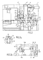
- Figure 1 is a schematic top view of an entire machine according to the invention.
- Figure 2 is a longitudinal section along the line II-II of figure 1.
- Figures 2a, 2b are detail views to scale enlarged means for fixing and guiding the jaws.
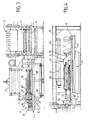
- FIG. 3 shows the jaw holding frame "laser”, in cross section along line III-III of Figure 1.
- Figure 4 shows the jaw holding frame "sparking", in cross section along line III, III of Figure 1.
- FIG. 5 shows the assembly of the tool carriage, in side view along line V-V in Figure 1.
- Figure 6 shows, in rear view, the chassis waiting for "laser” jaws.
- FIG. 7 shows the jaw holding frame "laser”, in cross section along line VII-VII of Figure 1.
- Figure 8 shows schematically, in section transverse, the shearing of the two edges.
- Figure 9 shows schematically, in section transverse, the passage of a laser welding torch.
- Figure 1 shows schematically, in view of above, a welding machine S for connecting the ends, respectively downstream and upstream, of two bands metallic M1, M2 which pass successively, following a longitudinal direction x'x, on a scroll path, for example a roller table T.
- the welding machine S shown schematically, in elevation, in Figure 2 is of the type described, for example, in French Patent No. 2,756,504 and includes two support frames, respectively a fixed frame 1 is a movable frame 1 ′ on which members are mounted holding device with two clamping jaws, respectively a member fixed holding 11 and a movable holding member 11 '.
- the fixed frame is constituted essentially two amounts spaced from each other and connected by crosspieces to form a rigid cage fixed on the foundation block 10 and the movable frame 1 'east also made up of a cage which is slidably mounted, parallel to the longitudinal axis x'x, between the two amounts of the fixed frame, the displacement of the movable frame being controlled by cylinders.
- the fixed holding member 11 comprises two jaws, respectively a lower jaw 12 and a upper jaw 13 on which jaws are mounted clamping, respectively a lower jaw 2 and a jaw higher 3.
- the lower jaw 12 forms a fixed base integral with the two uprights of the frame 1 and bearing on the foundation massif 10.
- the upper jaw 13 is slidably mounted vertically between the two uprights of the frame 1 and can be actuated by at least one jack 14, to ensure tightening bits.
- the ascent without load and the level settings of the upper jaw 13 are advantageously made by double-acting actuating cylinders.
- the movable holding member 11 ' is made so similar and therefore includes two jaws 12 ', 13' on which are mounted, respectively, a lower jaw 2 ' and an upper jaw 3 ', the tightening being controlled by 14 'cylinders.
- the metal strip M moves inside the two frames 1, 1 'along a horizontal plane of travel P1 and passes between the jaws of the two holding members 11, 11 'which are shown in the open position in the figure 2.
- the lower jaws 2, 2 ′ are associated with rollers of band support 16, 16 'which, however, must be independent of the jaws, as will be seen below.
- the jaws of the two holding members, respectively fixed and mobile are connected respectively, by conductors V, V 'at the two poles of a source of Electric power.
- each upper jaw 3, 3 ' can be detached from the jaw corresponding 13, 13 'to come to rest on the bit lower 2, 2 'and the assembly can be disassembled by transverse sliding along guide parts corresponding lower jaws 12, 12 '.
- a tool is advantageously used replacement mounted in a waiting frame placed next to it of the welding machine and comprising a table placed at the level of the two lower jaws and on which is slidingly mounted, transversely, a hanging carriage fitted with a removable hook which engages on both pairs of overlapping jaws to remove them from the machine and bring them on the table by transverse sliding.
- the used jaws can then be removed from the waiting frame and replaced by new jaws which are introduced into the machine by moving in the opposite direction.
- the welding machine is associated with a tool carriage on which are placed a double shears, a tool of replacement and, optionally, a planing tool for the welding.
- a tool carriage on which are placed a double shears, a tool of replacement and, optionally, a planing tool for the welding.
- Such an arrangement also makes it possible to place on the tool carriage a tool for welding by laser, which gives the possibility of welding, either by sparking or by laser depending on the nature of the welding bands.
- the jaws clamping devices for flash welding do not do not normally meet the requirements of the welding mode by laser.
- the invention makes it easy to replace the jaws usual by special clamping jaws which improve the shearing conditions without hindering the passage of the laser torch. In this way, we can realize on ends of the two sheets, facing edges rigorously straight and parallel which apply perfectly over each other, over the entire width of the joint to be welded, during the passage of the laser torch.
- the invention makes it possible to replace very quickly the clamping jaws without stopping the scrolling of the tape, during the end of the unwinding of the reel.
- the welding machine is associated with two waiting frames placed, respectively, on the side and on the other hand of the machine and allowing, on the one hand to remove the jaws in service to transfer them to a first waiting frame and secondly to transfer in the machine the replacement jaws on the second waiting frame.
- one of the waiting frame can be mounted on a tool trolley of the type described in French Patent No. 2,756,504 already cited.
- This tool carriage A is shown schematically, in elevation, in FIG. 4 and comprises, essentially, a horizontal frame 4 slidably mounted at the interior of a fixed frame 40 on guide rails 41 parallel to the longitudinal direction of travel x'x.
- On the chassis 4 are mounted several guide paths transverse, respectively a first path 4a for a replacement tooling D, a second path 4b for a double C shears, a third path 4c for a laser welding equipment L and a fourth path 4d for a planer R.
- FIG. 4 which is a side view along line III, III of Figure 1, the frame 10 carries an actuating cylinder 41 centered in the transverse mean plane Q and the stem of which is fitted with a hooking head which can engage removably, on the tools placed in this plane of work by lateral displacement of the carriage A.
- the tool carriage A moves sideways to center in work plan Q the guide path 4c of the laser welding tool L and it is moved transversely, along the joint, by the same cylinder operation 41.
- the welding machine is equipped with clamping jaws suitable for laser welding.
- Tool trolley A which is quite bulky, is placed normally, on the drive side according to the provision described in French patent 2,756,504 already cited. It therefore carries the holding frame E of the jaws “sparking”, as shown schematically on Figures 4 and 5.
- the auxiliary carriage B which serves only for reserve for "laser” jaws, can be of fairly large dimensions reduced and is therefore placed on the operator side of the as shown in Figures 1 and 3.
- each waiting frame E, B must be fitted with a jaw guide assembly consisting slides placed at the same level and in the extension corresponding slides arranged on the jaws 12, 13, 12 '13' of the two frames 1, 1 'of the machine so as to allow the transfer of the two pairs of jaws from the machine S on a waiting frame and vice versa, by sliding on the aligned guide assemblies, perpendicular to the longitudinal axis x'x of scrolling.
- the shear C is brought back on the tool carriage To whom is still advanced to center the apparatus laser welding L in the work plane Q and we welds. We can then resume scrolling, the second strip being driven by the first. So the machine downtime was limited to the time required for shearing, moving the tool carriage and laser welding.
- each jaw must be fixed on the jaw correspondingly removable allowing disassembly by transverse sliding of the jaw.
- each lower jaw 2, 2 ' is fixed on the corresponding jaw 12, 12 'by two rows of cylinders 21 with double T section each comprising a lower part, forming a piston, housed in a chamber formed in the jaw 12 and a enlarged upper part which engages in a groove 22 of corresponding profile, formed in the lower part jaw 2.
- the upper part of each cylinder 21 carries a roller 23 with an axis parallel to the axis longitudinal x'x which, in the high position of the jack 21, comes to rest on the bottom of the groove 22 to lift the bit 2.
- the cylinders 21 are double acting and determine so in a sense the application and fixing of the jaw 2 on the corresponding jaw 12 and, in the other direction, a slight lifting of the jaw 2 which can slide axially in rolling on the rollers 23.
- the two rows of cylinders 21 sliding in the grooves 22 of the jaw 2 constitute a guide path G2 of this one.
- each upper jaw 3, 3 ' is fixed on the corresponding jaw 13, 13 'by cylinders 31 arranged in two rows perpendicular to the longitudinal direction x'x.
- each cylinder 31 has a double T section and includes an upper part forming a piston, housed in a recess 32 of the upper jaw 13 and forming the chamber of a double-acting cylinder, and a lower part which engages in a transverse groove 33 in profile corresponding, formed on the upper part of the jaw 3.
- the latter is provided with two sections 34a, 34b which take support, in the lowered position, respectively on two rows rollers 15a, 15b mounted on suspension brackets fixed on the corresponding upper jaw 13.
- the double-acting cylinders 32 determine, in a sense, the lifting of the upper jaw 3 which is applied and fixed on the jaw 13 and, in the other direction, the lowering of the jaw 3 which comes to rest on the rollers 15a, 15b which constitute a path of bearing G3 cooperating with the grooves 33 to ensure a sliding guide of the jaw 3, perpendicular to the longitudinal direction x'x, at a level determined by rollers 15.
- the jaws are disassembled in a determined position of the jaws, respectively lower 12, 12 'and upper 13, 13'.
- the lateral uprights of the two frames 1, 1 ' are provided with sections of guide rails not shown placed, respectively, at the level of the guide paths G2, G3 formed, respectively, by the rows of rollers 23 of rolling of the lower jaws 2, 2 ′ and 15 of rolling of the upper jaws 3, 3 ', in the disassembly position of said bit.
- Figure 4 shows, in elevation, a tooling D of replacement of the two pairs of "sparking" jaws 2, 3, 2 ', 3 'of massive type, represented in FIG. 2 in their service position for which they are fixed on the corresponding jaws 12, 13, 12 ', 13'.
- the tool carriage A consists of a chassis 4 on which are mounted several transverse guide paths and, in particular, a guide path 4a for replacement tooling D "sparking" jaws mounted in a waiting frame E which can slide on the guide path 4a between a advanced position (indicated by solid lines in Figure 4), for which the end of the waiting frame E is close to the welding machine S and a position moved back (indicated in dashed line), which allows tool carriage movement A.
- the tool F to replace the jaws suitable for laser welding is mounted in a chassis standby B constituting an auxiliary carriage placed the other side of the tool carriage A in relation to the machine S and which can move, parallel to the axis longitudinal x'x, on rails 42, between a position of service, shown in solid lines in FIG. 6, for which the two pairs of laser jaws are centered on the work plan Q and a remote position shown schematically in phantom in Figure 6 and for which the welding machine S is released from the side operator.
- the machine S is advantageously equipped with a hood 18 connected to a welding residue suction circuit, which is swivel mounted on the fixed frame 1 and can be moved away to advance the auxiliary carriage B to the exchange position jaws and put back in place after the transfer, in the machine, laser jaws and the recoil of the carriage.
- a welding residue suction circuit which is swivel mounted on the fixed frame 1 and can be moved away to advance the auxiliary carriage B to the exchange position jaws and put back in place after the transfer, in the machine, laser jaws and the recoil of the carriage.
- the auxiliary carriage B consists of a chassis in the form of a frame 7 inside which the tooling replacement F is mounted to slide perpendicular to the longitudinal axis x'x of the machine.
- the replacement tool F comprises a member 6 jaw attachment, mounted on a carriage consisting of a chassis 61 in the form of a horizontal plate, which is carried by two pairs of rollers 62 which can roll in angles 71 with C section formed on both sides of the chassis 7 of the auxiliary carriage B.
- the attachment member 6 is carried by two flanges separated 64 fixed on the plate 61 and on which are articulated two pairs of hooks, respectively upper hooks 65 and lower hooks 65 ' made up of two arms articulated around horizontal axes and forming a deformable parallelogram actuated by a cylinder 66.
- the flanges 64 themselves carry two pairs of fixed arms 67 which abut on the laser jaws 20, 30 and these are provided with hanging rods 27, 37 which, in the stop position, are placed at the level notches formed at the ends of the attachment arms 65, 65 '. In this way, after hanging on the rods 27, 37, the carriage 6 can remove or repel the laser jaws 20, 30, either to introduce them into the welding machine A, or to remove them.
- the chassis 7 of the auxiliary carriage B carries a guide assembly H comprising two stages transverse guide members H2, H3 placed respectively, at the level and in the alignment of the organs corresponding guide G2, G3 of machine S, in the jaw disassembly position.
- frame 7 On the lower floor, frame 7 carries a table intermediate 70 on which are mounted two paths lower guide H2, H'2 each consisting of a pair of horizontal rails 72 which are placed in alignment with the rows of jacks 21 and the upper faces of which are formed at the level of the rollers 23 constituting the path of central guide G2, in the jaw disassembly position lower 2, 2 '.
- lower guide H2 H'2 each consisting of a pair of horizontal rails 72 which are placed in alignment with the rows of jacks 21 and the upper faces of which are formed at the level of the rollers 23 constituting the path of central guide G2, in the jaw disassembly position lower 2, 2 '.
- the chassis 7 for supporting the replacement tool F is provided, on its sides, respectively of two rows of rollers 73, 73 'forming a upper guide path H3 which extends at the same level and in alignment with the central guideway G3 comprising the two rows of rollers 15b, 15'b for supporting the parts rear of the upper jaws 3, 3 'in the raised position jaws 13, 13 '.
- the rollers rear 15b, 15'b of the jaws 13, 13 'therefore form, with the rollers 73, 73 'of the chassis 7, a raceway continuous on which can slide the dishes 34b, 34'b placed respectively behind the two upper jaws 30, 30 '.
- chassis 7 It would also be possible to place, at the party top of chassis 7, two rows of rollers arranged respectively in the extension of the rows of rollers 15a, 15'a for supporting the front part of the jaws 3, 3 '.
- the jaws after removing the welding machine, the jaws must be transportable in the workshop, to verification and it is advantageous, for this purpose, to remove from chassis 7.
- a line chassis 7 central support consisting of two rows of rollers 74, 74 'mounted on vertical supports 75 fixed on a central beam of chassis 7, in the plane longitudinal symmetry of it and that define a support plane placed at the level of the lower faces of the front ends 36, 36 ′ of the two upper jaws 30 ,. 30' when the latter are in the disassembly position.
- the central guide path G3 consisting of the rows of rollers 15a, 15b on which are supported the sections 34a, 34b is replaced by a guide path lateral H3 constituted, for each upper jaw 30, by the two rows of rollers 73 and 74 on which support, respectively the rear part and the front end 36 of the jaw 30.
- the displacement thereof is therefore effected without level change from machine S to waiting frame B and vice versa in the opposite direction for the introduction of the jaws on standby in machine S.
- the tool D of replacement of "sparking" jaws which is analogous to the F replacement tool for "laser” jaws and includes therefore a hooking member 5 slidingly mounted, perpendicular to the longitudinal axis x'x, on a frame stand E including a horizontal table 50 mounted sliding on the guide path 4a of the tool carriage 4 and two lateral uprights carrying rails guide 51 of a support table for the fastening member 5.
- the chassis E is provided, on the other hand, with a set lateral guide K similar to the guide assembly H of the waiting frame B of the laser jaws, comprising two stages K2, K3 placed at the same levels as the paths correspondents G2, G3 of the central assembly G, respectively a lower guide path K2 consisting two pairs of rails 52 mounted on the lower table 50, in alignment with the rows 21 of the jaws 12, 12 ' and an upper guide path K3 comprising two rows rear support rollers placed in line with the rows of rollers 15b and two rows of support rollers front mounted on spaced supports, in the plane longitudinal symmetry of the chassis E, at the faces lower of upper jaws 3, 3 '.
- a set lateral guide K similar to the guide assembly H of the waiting frame B of the laser jaws, comprising two stages K2, K3 placed at the same levels as the paths correspondents G2, G3 of the central assembly G, respectively a lower guide path K2 consisting two pairs of rails 52 mounted on the lower table 50, in alignment with the rows 21 of the jaws 12, 12
- the welding machine S is equipped with massive jaws, respectively lower 2 and upper 3, adapted to flash welding.
- massive jaws respectively lower 2 and upper 3, adapted to flash welding.
- a retraction of the attachment carriage 5 then makes it possible to transfer the spark jaws to frame E in the position shown in solid lines in FIG. 4, in sliding on the guide tracks K2, K3 of the chassis waiting E.
- the "sparking" jaws being thus removed, we can replace them with the "laser” jaws 20, 30 by advancing the attachment carriage 6 to position 6a shown in dashed lines in Figure 3.
- the "laser” jaws slide horizontally as indicated above on the guide paths H2, H3 to be placed inside of machine S.
- the lower jaws 20 pass over the lower central path G2 formed by the rollers 23 of the rows of jacks 21 and the upper jaws 30 pass over the upper central path G3 consisting of the rows of rollers 15a, 15b of the upper jaws 13, 13 '.
- the clamping cylinders 21 can then be actuated, 31, to apply and fix the "laser" jaws 20, 20 ', 30, 30 ', respectively on the lower jaws 12, 12' and on the upper jaws 13, 13 'of the two frames 1, 1'.
- the two pairs of "laser" jaws thus being fixed on the jaws, respectively 12, 12 ', 13, 13', we make advance the first band M1 and the next band M2 by so that their ends, respectively downstream and upstream are on both sides of the work plan Q.
- the clamping, respectively of the upstream jaws is then controlled 20, 30 on the M1 strip and downstream jaws 20 ', 30' on the strip M2 in the position shown in FIG. 7.
- a shear is advantageously used double 8 of the type described in the previous patent 2,756,504, which includes two pairs of circular blades, respectively an upper blade 8a and a lower blade 8b.
- Two shear planes are thus defined, respectively upstream E1 and downstream E2 apart on the one hand and on the other side of the work plan Q.
- the blades of each pair are placed on either side of the plane of shear, the upper blades 8a being offset, by preferably inward and lower blades 8b outwards.
- the "laser" jaws 20, 30 and the “sparking" jaws 2, 3 are fixed and guided in the same way on the jaws 12, 12 ', 13, 13' of the two organs of maintenance but they differ essentially in the form of their front part facing the shearing plane.
- sparking jaws are made so classic and, as shown schematically in Figure 5, their front clamping part is massive enough to allow the application of a longitudinal forging force of the joint during welding.
- the front clamping parts of the "laser" jaws 20, 30, 20 ', 30 ' form a tapered beak 28, 38, 28', 38 'which projects points to an end 36, 36 'as close together as possible from the shear plane E1, E2.
- the beaks thus formed at the ends of the jaws of tightening are not necessarily symmetrical, their shape tapered depending on the template to leave for the passage of the part of the laser equipment which must remain close to the welding.
- the external faces of clamping parts 28, 38, 28 ', 38' will be inclined by relative to the horizontal by an angle greater than 45 °.
- the lower blade 8b can pass partly to the below the upper spout 38 so that the plane of shear E1 is as close as possible to the end 36a thereof.
- the overhang (p) is at say the distance between the shear plane E1 and the end 35a of the jaw can thus be as reduced as possible and is limited, in practice, to a few millimeters.
- the offset of the end 36b of the lower jaw 20 relative to the end 36a of the jaw upper 30 further improves the quality of the shear, the sheet being pressed on the upper jaw by the blade lower 8b.
- clamping jaws which have been described could have another form allowing to ensure excellent shearing and allowing passage a laser torch.
Landscapes
- Physics & Mathematics (AREA)
- Optics & Photonics (AREA)
- Engineering & Computer Science (AREA)
- Mechanical Engineering (AREA)
- Plasma & Fusion (AREA)
- Laser Beam Processing (AREA)
- Automatic Assembly (AREA)
- Arc Welding In General (AREA)
- Processing Of Solid Wastes (AREA)
Applications Claiming Priority (2)
| Application Number | Priority Date | Filing Date | Title |
|---|---|---|---|
| FR0002120A FR2805186B1 (fr) | 2000-02-21 | 2000-02-21 | Machine a rabouter des bandes metalliques et son procede de mise en oeuvre |
| FR0002120 | 2000-02-21 |
Publications (2)
| Publication Number | Publication Date |
|---|---|
| EP1127654A1 true EP1127654A1 (de) | 2001-08-29 |
| EP1127654B1 EP1127654B1 (de) | 2005-11-16 |
Family
ID=8847201
Family Applications (1)
| Application Number | Title | Priority Date | Filing Date |
|---|---|---|---|
| EP01400436A Expired - Lifetime EP1127654B1 (de) | 2000-02-21 | 2001-02-19 | Verfahren und Vorrichtung zum Stumpfschweissen von metallischen Blechen |
Country Status (6)
| Country | Link |
|---|---|
| US (1) | US6504128B2 (de) |
| EP (1) | EP1127654B1 (de) |
| AT (1) | ATE309880T1 (de) |
| DE (1) | DE60114901T2 (de) |
| ES (1) | ES2252165T3 (de) |
| FR (1) | FR2805186B1 (de) |
Cited By (2)
| Publication number | Priority date | Publication date | Assignee | Title |
|---|---|---|---|---|
| CN104858539A (zh) * | 2015-05-08 | 2015-08-26 | 宁波福耀汽车零部件有限公司 | 一种实现钢带在线点焊治具 |
| CN109880953A (zh) * | 2019-04-11 | 2019-06-14 | 中冶赛迪工程技术股份有限公司 | 一种开口机换钎设备 |
Families Citing this family (13)
| Publication number | Priority date | Publication date | Assignee | Title |
|---|---|---|---|---|
| US7071438B2 (en) * | 2003-03-07 | 2006-07-04 | Praxair Technology, Inc. | Gas composition for arc welding |
| DE102009020146B3 (de) * | 2009-04-08 | 2010-06-10 | V & M Deutschland Gmbh | Verfahren und Vorrichtung zum Verbinden der Enden von Rohren aus Stahl mittels Orbitalschweißen in Hybridtechnik |
| FR2986170B1 (fr) * | 2012-01-26 | 2014-03-07 | Jfp Microtechnic | Procede et dispositif de soudage, notamment par laser, de fils sur un substrat |
| US20150224606A1 (en) * | 2014-02-13 | 2015-08-13 | Emmanuel L'Ecuyer | Welding system for continuous rod, and welding head therefore |
| RU2555288C1 (ru) * | 2014-02-20 | 2015-07-10 | Открытое акционерное общество "Волгоградский научно-исследовательский и проектный институт технологии химического и нефтяного аппаратостроения" (ОАО "ВНИИПТхимнефтеаппаратуры") | Установка для односторонней автоматической сварки полотнищ |
| RU2599472C2 (ru) * | 2014-09-23 | 2016-10-10 | Акционерное общество "Атомэнергопроект" (АО "Атомэнергопрект") | Установка для изготовления строительного облицовочного полотна из металлических листов |
| US10049141B2 (en) | 2014-10-10 | 2018-08-14 | salesforce.com,inc. | Declarative specification of visualization queries, display formats and bindings |
| CN104668774A (zh) * | 2015-02-25 | 2015-06-03 | 昆山宝锦激光拼焊有限公司 | 一种串联式焊接机 |
| US10821548B2 (en) * | 2015-03-20 | 2020-11-03 | Honda Motor Co., Ltd. | Plate-material abutting device |
| CN111085814A (zh) * | 2019-12-17 | 2020-05-01 | 苏州领裕电子科技有限公司 | 一种具有双焊接治具的焊接设备 |
| CN116252058B (zh) * | 2022-09-07 | 2026-02-17 | 武汉凯奇冶金焊接设备制造有限责任公司 | 一种高精度激光焊机夹钳压紧装置 |
| CN116100150A (zh) * | 2022-11-21 | 2023-05-12 | 佛山市精信达五金电器有限公司 | 一种高效率的双工件同步连续自动焊接装配装置 |
| CN118115048B (zh) * | 2024-04-30 | 2024-07-23 | 山东天乐塑料科技有限公司 | 一种基于托盘焊接夹具的产品质量评估系统 |
Citations (5)
| Publication number | Priority date | Publication date | Assignee | Title |
|---|---|---|---|---|
| LU58010A1 (de) * | 1968-02-20 | 1969-05-22 | ||
| DE6941193U (de) * | 1969-10-23 | 1970-06-11 | Hopp Ing Buero | Vorrichtung zum zusammenschweissen dicker bleche. |
| EP0438615A1 (de) * | 1990-01-23 | 1991-07-31 | Thyssen Industrie Ag Maschinenbau | Einrichtung zum Verbinden von mindestens zwei Blechen durch wenigstens eine durch eine Laserstrahlschweissvorrichtung hergestellte Schweissnaht |
| DE4100302C1 (de) * | 1991-01-08 | 1992-02-06 | Bwg Bergwerk- Und Walzwerk-Maschinenbau Gmbh, 4100 Duisburg, De | |
| EP0807487A2 (de) * | 1996-05-13 | 1997-11-19 | Krupp Drauz Ingenieurbetrieb GmbH | Einrichtung zum Transportieren, Spannen und Laserstrahlschweissen von mindestens zwei Blechplatinen |
Family Cites Families (5)
| Publication number | Priority date | Publication date | Assignee | Title |
|---|---|---|---|---|
| FR58010E (fr) | 1948-02-13 | 1953-09-21 | Chaîne à rouleaux à surfaces d'usure latérales | |
| DE2341255C2 (de) * | 1973-08-16 | 1982-08-26 | Hugo Miebach Gmbh, 4600 Dortmund | Abbrennstumpfschweißmaschine zum Verbinden von Bändern |
| JPS62282783A (ja) * | 1986-05-31 | 1987-12-08 | Mitsubishi Electric Corp | 金属ストリツプの接続方法およびその装置 |
| EP0438609B1 (de) * | 1990-01-20 | 1993-09-01 | Thyssen Industrie Ag Maschinenbau | Verfahren und Einrichtung zum Aneinanderschweissen von Stahlblechen mittels Laserstrahlschweissverfahren |
| FR2756504B1 (fr) * | 1996-11-29 | 1999-05-07 | Kvaerner Clecim | Machine automatique de raccordement transversal de bandes metalliques |
-
2000
- 2000-02-21 FR FR0002120A patent/FR2805186B1/fr not_active Expired - Fee Related
-
2001
- 2001-02-19 EP EP01400436A patent/EP1127654B1/de not_active Expired - Lifetime
- 2001-02-19 ES ES01400436T patent/ES2252165T3/es not_active Expired - Lifetime
- 2001-02-19 DE DE60114901T patent/DE60114901T2/de not_active Expired - Fee Related
- 2001-02-19 AT AT01400436T patent/ATE309880T1/de not_active IP Right Cessation
- 2001-02-21 US US09/788,360 patent/US6504128B2/en not_active Expired - Fee Related
Patent Citations (5)
| Publication number | Priority date | Publication date | Assignee | Title |
|---|---|---|---|---|
| LU58010A1 (de) * | 1968-02-20 | 1969-05-22 | ||
| DE6941193U (de) * | 1969-10-23 | 1970-06-11 | Hopp Ing Buero | Vorrichtung zum zusammenschweissen dicker bleche. |
| EP0438615A1 (de) * | 1990-01-23 | 1991-07-31 | Thyssen Industrie Ag Maschinenbau | Einrichtung zum Verbinden von mindestens zwei Blechen durch wenigstens eine durch eine Laserstrahlschweissvorrichtung hergestellte Schweissnaht |
| DE4100302C1 (de) * | 1991-01-08 | 1992-02-06 | Bwg Bergwerk- Und Walzwerk-Maschinenbau Gmbh, 4100 Duisburg, De | |
| EP0807487A2 (de) * | 1996-05-13 | 1997-11-19 | Krupp Drauz Ingenieurbetrieb GmbH | Einrichtung zum Transportieren, Spannen und Laserstrahlschweissen von mindestens zwei Blechplatinen |
Cited By (3)
| Publication number | Priority date | Publication date | Assignee | Title |
|---|---|---|---|---|
| CN104858539A (zh) * | 2015-05-08 | 2015-08-26 | 宁波福耀汽车零部件有限公司 | 一种实现钢带在线点焊治具 |
| CN109880953A (zh) * | 2019-04-11 | 2019-06-14 | 中冶赛迪工程技术股份有限公司 | 一种开口机换钎设备 |
| CN109880953B (zh) * | 2019-04-11 | 2024-03-12 | 中冶赛迪工程技术股份有限公司 | 一种开口机换钎设备 |
Also Published As
| Publication number | Publication date |
|---|---|
| FR2805186A1 (fr) | 2001-08-24 |
| DE60114901D1 (de) | 2005-12-22 |
| US6504128B2 (en) | 2003-01-07 |
| ES2252165T3 (es) | 2006-05-16 |
| ATE309880T1 (de) | 2005-12-15 |
| US20020036189A1 (en) | 2002-03-28 |
| EP1127654B1 (de) | 2005-11-16 |
| FR2805186B1 (fr) | 2002-06-21 |
| DE60114901T2 (de) | 2006-08-03 |
Similar Documents
| Publication | Publication Date | Title |
|---|---|---|
| EP0845309B1 (de) | Automatische Maschine zum transversal Verbinden von Metallbändern | |
| EP1127654B1 (de) | Verfahren und Vorrichtung zum Stumpfschweissen von metallischen Blechen | |
| EP2064023B1 (de) | Vorrichtung und verfahren zur schweissverbindung von bahnenmetallstreifen | |
| JP5438163B2 (ja) | 造管設備に適用される鉄板ストリップ接合装置 | |
| FR2553692A1 (fr) | Procede et dispositif de fabrication de caillebotis | |
| CA1093346A (fr) | Methode et machine de soudage automatique de tubes chanfreines | |
| EP0659518B1 (de) | Anlage zum Aneinanderfügen und zum Schweissen von zwei aufgewickelten Metallbänder mittels eines Laserstrahls um ein kontinuierliches Metallband herzustellen | |
| FR2801820A1 (fr) | Appareil et procede d'assemblage de bandes | |
| CH444631A (fr) | Procédé pour joindre les extrémités de deux feuillards et installation pour sa mise en oeuvre | |
| EP0835712A1 (de) | Verfahren zum Schweissen mindestens eines Schienenstranges und Maschine zur Anwendung dieses Verfahrens | |
| CH464634A (fr) | Dispositif pour joindre par soudage deux bandes de matières | |
| EP1230060A1 (de) | Verfahren und vorrichtung zum brennschneiden eines aus stahl hergestellen werkstückes | |
| FR2597290A1 (fr) | Procede et appareil de fabrication de faisceaux de conducteurs | |
| CH625149A5 (de) | ||
| CN110280952B (zh) | 一种多工位焊接夹具 | |
| FR2524835A1 (fr) | Procede et appareil d'ebarbage de plaques decoupees | |
| EP0018868A1 (de) | Vorrichtung zum in der Längsrichtung Schneiden von Brammen mittels Sauerstoffbrennschneiden | |
| EP0467001B1 (de) | Zug zum Verlegen neuer Gleise und Verfahren zum Verlegen derselben mit einem solchen Zug | |
| FR2597512A1 (fr) | Procede et dispositif pour la mise en place de collets en tole d'aluminium ou analogue sur les raccords de tiges a anode faisant saillie de blocs d'anode | |
| EP0650796A1 (de) | Verfahren und Vorrichtung zum Herstellen der Rechtwinkligkeit und zum Verschweissen metallischer Bänder | |
| FR2703274A1 (fr) | Procédé et installation de soudage de bandes métalliques. | |
| EP0252844B1 (de) | Automatische Vorrichtung zum Bearbeiten, insbesondere zum Schneiden von Bändern | |
| EP0781621B1 (de) | Verfahren zum Spleissen von metallischen Bändern und Maschine zur Durchführung des Verfahrens | |
| FR2770160A1 (fr) | Machine automatique de raccordement transversal de bandes metalliques | |
| EP1424148B1 (de) | Pressenanlage mit einem Auflagetisch für das Band |
Legal Events
| Date | Code | Title | Description |
|---|---|---|---|
| PUAI | Public reference made under article 153(3) epc to a published international application that has entered the european phase |
Free format text: ORIGINAL CODE: 0009012 |
|
| AK | Designated contracting states |
Kind code of ref document: A1 Designated state(s): AT BE CH CY DE DK ES FI FR GB GR IE IT LI LU MC NL PT SE TR Kind code of ref document: A1 Designated state(s): AT BE DE ES FR IT |
|
| AX | Request for extension of the european patent |
Free format text: AL;LT;LV;MK;RO;SI |
|
| RIN1 | Information on inventor provided before grant (corrected) |
Inventor name: ZENNAF, BRAHIM Inventor name: SAVAETE, FRANCOIS |
|
| 17P | Request for examination filed |
Effective date: 20020228 |
|
| AKX | Designation fees paid |
Free format text: AT BE DE ES FR IT |
|
| GRAP | Despatch of communication of intention to grant a patent |
Free format text: ORIGINAL CODE: EPIDOSNIGR1 |
|
| GRAS | Grant fee paid |
Free format text: ORIGINAL CODE: EPIDOSNIGR3 |
|
| GRAA | (expected) grant |
Free format text: ORIGINAL CODE: 0009210 |
|
| AK | Designated contracting states |
Kind code of ref document: B1 Designated state(s): AT BE DE ES FR IT |
|
| PG25 | Lapsed in a contracting state [announced via postgrant information from national office to epo] |
Ref country code: AT Free format text: LAPSE BECAUSE OF FAILURE TO SUBMIT A TRANSLATION OF THE DESCRIPTION OR TO PAY THE FEE WITHIN THE PRESCRIBED TIME-LIMIT Effective date: 20051116 |
|
| REF | Corresponds to: |
Ref document number: 60114901 Country of ref document: DE Date of ref document: 20051222 Kind code of ref document: P |
|
| RAP2 | Party data changed (patent owner data changed or rights of a patent transferred) |
Owner name: VAI CLECIM |
|
| REG | Reference to a national code |
Ref country code: ES Ref legal event code: FG2A Ref document number: 2252165 Country of ref document: ES Kind code of ref document: T3 |
|
| PLBE | No opposition filed within time limit |
Free format text: ORIGINAL CODE: 0009261 |
|
| STAA | Information on the status of an ep patent application or granted ep patent |
Free format text: STATUS: NO OPPOSITION FILED WITHIN TIME LIMIT |
|
| 26N | No opposition filed |
Effective date: 20060817 |
|
| PGFP | Annual fee paid to national office [announced via postgrant information from national office to epo] |
Ref country code: ES Payment date: 20090313 Year of fee payment: 9 |
|
| PGFP | Annual fee paid to national office [announced via postgrant information from national office to epo] |
Ref country code: BE Payment date: 20090218 Year of fee payment: 9 |
|
| PGFP | Annual fee paid to national office [announced via postgrant information from national office to epo] |
Ref country code: DE Payment date: 20090420 Year of fee payment: 9 Ref country code: IT Payment date: 20090225 Year of fee payment: 9 |
|
| PGFP | Annual fee paid to national office [announced via postgrant information from national office to epo] |
Ref country code: FR Payment date: 20090217 Year of fee payment: 9 |
|
| BERE | Be: lapsed |
Owner name: *VAI CLECIM Effective date: 20100228 |
|
| REG | Reference to a national code |
Ref country code: FR Ref legal event code: ST Effective date: 20101029 |
|
| PG25 | Lapsed in a contracting state [announced via postgrant information from national office to epo] |
Ref country code: FR Free format text: LAPSE BECAUSE OF NON-PAYMENT OF DUE FEES Effective date: 20100301 |
|
| PG25 | Lapsed in a contracting state [announced via postgrant information from national office to epo] |
Ref country code: BE Free format text: LAPSE BECAUSE OF NON-PAYMENT OF DUE FEES Effective date: 20100228 Ref country code: DE Free format text: LAPSE BECAUSE OF NON-PAYMENT OF DUE FEES Effective date: 20100901 |
|
| REG | Reference to a national code |
Ref country code: ES Ref legal event code: FD2A Effective date: 20110330 |
|
| PG25 | Lapsed in a contracting state [announced via postgrant information from national office to epo] |
Ref country code: IT Free format text: LAPSE BECAUSE OF NON-PAYMENT OF DUE FEES Effective date: 20100219 |
|
| PG25 | Lapsed in a contracting state [announced via postgrant information from national office to epo] |
Ref country code: ES Free format text: LAPSE BECAUSE OF NON-PAYMENT OF DUE FEES Effective date: 20110317 |
|
| PG25 | Lapsed in a contracting state [announced via postgrant information from national office to epo] |
Ref country code: ES Free format text: LAPSE BECAUSE OF NON-PAYMENT OF DUE FEES Effective date: 20100220 |