EP1127717A2 - Luftreifen - Google Patents
Luftreifen Download PDFInfo
- Publication number
- EP1127717A2 EP1127717A2 EP01300265A EP01300265A EP1127717A2 EP 1127717 A2 EP1127717 A2 EP 1127717A2 EP 01300265 A EP01300265 A EP 01300265A EP 01300265 A EP01300265 A EP 01300265A EP 1127717 A2 EP1127717 A2 EP 1127717A2
- Authority
- EP
- European Patent Office
- Prior art keywords
- tire
- radial direction
- bead
- pneumatic tire
- reinforcing cord
- Prior art date
- Legal status (The legal status is an assumption and is not a legal conclusion. Google has not performed a legal analysis and makes no representation as to the accuracy of the status listed.)
- Withdrawn
Links
Images


Classifications
-
- B—PERFORMING OPERATIONS; TRANSPORTING
- B60—VEHICLES IN GENERAL
- B60C—VEHICLE TYRES; TYRE INFLATION; TYRE CHANGING; CONNECTING VALVES TO INFLATABLE ELASTIC BODIES IN GENERAL; DEVICES OR ARRANGEMENTS RELATED TO TYRES
- B60C15/00—Tyre beads, e.g. ply turn-up or overlap
- B60C15/0009—Tyre beads, e.g. ply turn-up or overlap features of the carcass terminal portion
- B60C15/0027—Tyre beads, e.g. ply turn-up or overlap features of the carcass terminal portion with low ply turn-up, i.e. folded around the bead core and terminating at the bead core
-
- B—PERFORMING OPERATIONS; TRANSPORTING
- B60—VEHICLES IN GENERAL
- B60C—VEHICLE TYRES; TYRE INFLATION; TYRE CHANGING; CONNECTING VALVES TO INFLATABLE ELASTIC BODIES IN GENERAL; DEVICES OR ARRANGEMENTS RELATED TO TYRES
- B60C15/00—Tyre beads, e.g. ply turn-up or overlap
- B60C15/06—Flipper strips, fillers, or chafing strips and reinforcing layers for the construction of the bead
-
- B—PERFORMING OPERATIONS; TRANSPORTING
- B60—VEHICLES IN GENERAL
- B60C—VEHICLE TYRES; TYRE INFLATION; TYRE CHANGING; CONNECTING VALVES TO INFLATABLE ELASTIC BODIES IN GENERAL; DEVICES OR ARRANGEMENTS RELATED TO TYRES
- B60C15/00—Tyre beads, e.g. ply turn-up or overlap
- B60C15/06—Flipper strips, fillers, or chafing strips and reinforcing layers for the construction of the bead
- B60C15/0603—Flipper strips, fillers, or chafing strips and reinforcing layers for the construction of the bead characterised by features of the bead filler or apex
- B60C15/0607—Flipper strips, fillers, or chafing strips and reinforcing layers for the construction of the bead characterised by features of the bead filler or apex comprising several parts, e.g. made of different rubbers
-
- Y—GENERAL TAGGING OF NEW TECHNOLOGICAL DEVELOPMENTS; GENERAL TAGGING OF CROSS-SECTIONAL TECHNOLOGIES SPANNING OVER SEVERAL SECTIONS OF THE IPC; TECHNICAL SUBJECTS COVERED BY FORMER USPC CROSS-REFERENCE ART COLLECTIONS [XRACs] AND DIGESTS
- Y10—TECHNICAL SUBJECTS COVERED BY FORMER USPC
- Y10T—TECHNICAL SUBJECTS COVERED BY FORMER US CLASSIFICATION
- Y10T152/00—Resilient tires and wheels
- Y10T152/10—Tires, resilient
- Y10T152/10495—Pneumatic tire or inner tube
- Y10T152/10819—Characterized by the structure of the bead portion of the tire
-
- Y—GENERAL TAGGING OF NEW TECHNOLOGICAL DEVELOPMENTS; GENERAL TAGGING OF CROSS-SECTIONAL TECHNOLOGIES SPANNING OVER SEVERAL SECTIONS OF THE IPC; TECHNICAL SUBJECTS COVERED BY FORMER USPC CROSS-REFERENCE ART COLLECTIONS [XRACs] AND DIGESTS
- Y10—TECHNICAL SUBJECTS COVERED BY FORMER USPC
- Y10T—TECHNICAL SUBJECTS COVERED BY FORMER US CLASSIFICATION
- Y10T152/00—Resilient tires and wheels
- Y10T152/10—Tires, resilient
- Y10T152/10495—Pneumatic tire or inner tube
- Y10T152/10819—Characterized by the structure of the bead portion of the tire
- Y10T152/10828—Chafer or sealing strips
-
- Y—GENERAL TAGGING OF NEW TECHNOLOGICAL DEVELOPMENTS; GENERAL TAGGING OF CROSS-SECTIONAL TECHNOLOGIES SPANNING OVER SEVERAL SECTIONS OF THE IPC; TECHNICAL SUBJECTS COVERED BY FORMER USPC CROSS-REFERENCE ART COLLECTIONS [XRACs] AND DIGESTS
- Y10—TECHNICAL SUBJECTS COVERED BY FORMER USPC
- Y10T—TECHNICAL SUBJECTS COVERED BY FORMER US CLASSIFICATION
- Y10T152/00—Resilient tires and wheels
- Y10T152/10—Tires, resilient
- Y10T152/10495—Pneumatic tire or inner tube
- Y10T152/10819—Characterized by the structure of the bead portion of the tire
- Y10T152/10837—Bead characterized by the radial extent of apex, flipper or chafer into tire sidewall
-
- Y—GENERAL TAGGING OF NEW TECHNOLOGICAL DEVELOPMENTS; GENERAL TAGGING OF CROSS-SECTIONAL TECHNOLOGIES SPANNING OVER SEVERAL SECTIONS OF THE IPC; TECHNICAL SUBJECTS COVERED BY FORMER USPC CROSS-REFERENCE ART COLLECTIONS [XRACs] AND DIGESTS
- Y10—TECHNICAL SUBJECTS COVERED BY FORMER USPC
- Y10T—TECHNICAL SUBJECTS COVERED BY FORMER US CLASSIFICATION
- Y10T152/00—Resilient tires and wheels
- Y10T152/10—Tires, resilient
- Y10T152/10495—Pneumatic tire or inner tube
- Y10T152/10819—Characterized by the structure of the bead portion of the tire
- Y10T152/10846—Bead characterized by the chemical composition and or physical properties of elastomers or the like
-
- Y—GENERAL TAGGING OF NEW TECHNOLOGICAL DEVELOPMENTS; GENERAL TAGGING OF CROSS-SECTIONAL TECHNOLOGIES SPANNING OVER SEVERAL SECTIONS OF THE IPC; TECHNICAL SUBJECTS COVERED BY FORMER USPC CROSS-REFERENCE ART COLLECTIONS [XRACs] AND DIGESTS
- Y10—TECHNICAL SUBJECTS COVERED BY FORMER USPC
- Y10T—TECHNICAL SUBJECTS COVERED BY FORMER US CLASSIFICATION
- Y10T152/00—Resilient tires and wheels
- Y10T152/10—Tires, resilient
- Y10T152/10495—Pneumatic tire or inner tube
- Y10T152/10855—Characterized by the carcass, carcass material, or physical arrangement of the carcass materials
- Y10T152/10864—Sidewall stiffening or reinforcing means other than main carcass plies or foldups thereof about beads
Definitions
- This invention relates to pneumatic tires, and more particularly to a pneumatic radial tire for use in relatively small-size vehicles such as passenger cars, vans, pickups and the like simultaneously improving steering stability, road noise (hereinafter abbreviated as R/N) performance and ride comfort while dominantly holding tire weight, rolling resistance and the like.
- R/N road noise
- an object of the invention to provide a pneumatic tire simultaneously and drastically improving the steering stability, ride comfort and R/N performance while ensuring at least an existing tire weight and holding an existing low rolling resistance.
- a pneumatic tire comprising a tread portion, a pair of sidewall portions, a pair of bead portions, a radial carcass extending between a pair of bead cores embedded in the respective bead portion to reinforce these portions and having a turnup portion wound around the bead core from an inside of the tire toward an outside thereof, a bead filler rubber of a triangular shape at section taperingly extending from the bead core toward an end of the tread portion, and one or more reinforcing cord layers arranged at a side face zone ranging from the bead portion to the sidewall portion, in which the reinforcing cord layer is a layer of one or more rubberized cords spirally wound about an axial line of the tire and has an inner end in a radial direction of the tire between a position located outward from an outer periphery of the bead core in the radial direction and a position located inward from a tapered end of the bead fill
- the inner end of the reinforcing cord layer is located in a position separated from the outer periphery of the bead core by a distance in the radial direction corresponding to 3-50% of a tire section height.
- an outer end of the reinforcing cord layer in the radial direction is located in a position separated from a rim diameter line by a distance in the radial direction corresponding to 10-75% of a tire section height.
- the cord of the reinforcing cord layer is a cord selected from nylon cord, polyester cord, rayon cord, aramid cord and steel cord.
- the reinforcing cord layer has an end count of 15-60 cords/5 cm.
- the bead filler rubber has a JIS hardness at 30°C of 65-83.
- an end of the turnup portion of the radial carcass has a height in the radial direction corresponding to 5-45% of the tire section height.
- the reinforcing cord layer is arranged along an outside of the turnup portion of the radial carcass or along an inside of the turnup portion of the radial carcass.
- an outer end of the reinforcing cord layer in the radial direction exceeds an end of the turnup portion of the radial carcass in the radial direction.
- a reinforcing sheet rubber extending toward the end of the tread portion is arranged along a tapered end portion of the bead filler rubber so as to contact therewith and has an even thickness of not more than 2 mm.
- an outer end of the reinforcing sheet rubber in the radial direction is located in a position separated from the rim diameter line to 30-75% of the tire section height.
- tire section height used throughout the specification means "a half of a difference between an overall diameter of a tire and a rim diameter when the tire is mounted onto an approved rim and inflated under a specified air pressure without loading” as defined in JATMA YEAR BOOK (1999).
- rim diameter line used herein means a straight line passing through a position corresponding to a rim diameter and in parallel to an axial line of the tire.
- JIS hardness used herein means a hardness of rubber measured according to JIS K6253-1993.
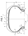
- a tire 1 shown in Fig. 1 is a pneumatic radial tire for use in relatively small-size vehicles as previously mentioned.
- This tire 1 comprises a pair of bead portions 2, a pair of sidewall portions 3 and a tread portion 4.
- These portions 2, 3, 4 are reinforced with a radial carcass 6 of one or more plies, one ply in the illustrated embodiment, extending between a pair of bead cores 5 each embedded in the respective bead portion 2.
- the tread portion 4 is strengthened with a belt 7 disposed on an outer periphery of the radial carcass 6.
- the tread portion 4 is provided with a tread rubber 8 disposed at an outer peripheral side of the belt 7.
- the radial carcass 6 has a turnup portion 6t wound around the bead core 5 from an inside of the tire 1 toward an outside thereof.
- a ply cord of the radial carcass 6 use may be made of organic fiber cords such as nylon cord, polyester cord, rayon cord, aramid cord and the like, inorganic fiber cords such as carbon fiber cord and the like, and steel cord.
- the bead portion 2 is provided with a bead filler rubber 9 taperingly extending from the bead core 5 toward an end of the tread portion 4 and having a triangular shape at its section.
- the tire 1 is provided with one or more reinforcing cord layers, one reinforcing cord layer 10 in the illustrated embodiment, disposed in a side face zone ranging from the bead portion 2 to the sidewall portion 3.
- the reinforcing cord layer 10 is a cord layer formed by spirally winding one or more rubberized cords, one rubberized cord 10C in the illustrated embodiment, about an axial line X of the tire 1.
- adjoining rubberized cords 10C ranging from a winding start end 10s to a winding terminal end 10e are shown so as to separate from each other in Fig. 2, but these adjoining rubberized cords 10C are actually joined to each other at least in the tire 1 to form a completely layer-shaped cord layer 10.
- the spirally wound cord layer as the reinforcing cord layer 10 has an inner end 10ie existing between a position located outward from an outer periphery 5os of the bead core 5 in a radial direction of the tire and a position located inward from a tapered end 9p of the bead filler rubber 9 in the radial direction of the tire.
- the quality of the steering stability is not determined by the degree of the tire whole rigidity but is determined by degrees of a rigidity of a side face zone ranging from the bead portion 2 to the sidewall portion 3 and a rigidity of the tread portion 4.
- the rigidity of the side face zone plays an important role for the steering stability and consists of a lateral rigidity component substantially perpendicular to a running direction of the tire 1 and a rigidity component in the running direction or longitudinal direction, which depend the quality of the steering stability.
- the side face zone including the reinforcing cord layer 10 at the ground contact area of the tread portion 4 increases a deformation quantity expanding outward from the tire 1 as compared with the conventional one.
- the ground contacting deformation is absorbed at the low hysteresis loss region and hence the rolling resistance is at least reduced as compared with that of the conventional tire.
- a height h 9 of the tapered end 9p of the bead filler rubber 9 from a rim diameter line RL is not more than 50% of a section height SH of the tire 1.
- the organic fiber cord or inorganic fiber cord has a specific gravity smaller than that of rubber, so that the weight of the tire 1 can be controlled to a level equal to or less than that of the conventional tire.
- the arrangement of the spirally wound cord layer as the reinforcing cord layer 10 in the side face zone of the tire 1 is based on the utilization of anisotropic property, which can not be obtained in the high-hardness bead filler rubber 9 or high-hardness sheet-shaped rubber, i.e. a property that the rigidity in the longitudinal direction of the tire 1 is high and the rigidity in the radial direction is low whereby the steering stability can be largely improved with rather improving the ride comfort and R/N performance, which have been sacrificed in the conventional technique.
- the inner end 10ie of the reinforcing cord layer 10 is located in a position separated from the outer periphery of the bead core 5 by a distance ⁇ in the radial direction corresponding to 3-50%, preferably 30-50% of a section height SH of the tire 1.
- an outer end 10oe of the reinforcing cord layer 10 in the radial direction is located in a position separated from a rim diameter line RL by a distance H in the radial direction corresponding to 10-75%, preferably 50-75% of the section height SH of the tire 1.
- the distance H is outside the above range, the improvements of the steering stability, ride comfort and R/N performance are obstructed.
- the cord 10C is selected from nylon cord, polyester cord, rayon cord, aramid cord and steel cord. The selection from these cords is dependent upon the requirement of steering stability, ride comfort and R/N performance.
- the end count of the spirally wound cord 10C in the reinforcing cord layer 10 is 15-60 cords/5 cm.
- the term "end count” used herein means the number of cords 10C per unit length measured in a direction perpendicular to an axial line of the cord, 5 cm in the invention. The end count is set by the kind of the cord 10C in conjunction with the above performances.
- the bead filler rubber 9 has a JIS hardness at 30°C of 65-83, preferably 70-80. When the hardness is outside the above range, the simultaneous improvement of the steering stability, ride comfort and R/N performance is obstructed.
- the height h 6t of the turnup portion 6t of the radial carcass 6 from the rim diameter line RL in the radial direction is 5-45% of the section height SH of the tire 1.
- the reinforcing cord layer 10 may be arranged along an outside of the turnup portion 6t of the radial carcass 6 as shown in a left half of Fig. 1 with respect to an equatorial plane E of the tire and Figs. 3 and 5, or along an inside of the turnup portion 6t of the radial carcass 6 as shown in a right half of Fig. 1 with respect to the equatorial plane E and Fig. 4.
- Fig. 1 shows a mixed use of these arrangements, but a case of arranging only outside the turnup portion 6t and a case of arranging only inside the turnup portion 6t may be used.
- the bead portion durability is improved, while when it is arranged inside the turnup portion 6t, the bead portion durability somewhat lowers, but the building efficiency becomes higher because a composite material formed by previously uniting an uncured member for the bead filler rubber 9 with an uncured member for the reinforcing cord layer 10 can be used at a tire building stage.
- the outer end of the reinforcing cord layer 10 in the radial direction corresponding to the distance H exceeds the height h 6t of the turnup portion 6t of the radial carcass in the radial direction, i.e. H>h 6t . If H ⁇ h 6t , stress and strain concentrate in the end part of the turnup portion 6t and hence there is caused a problem that troubles are started from such an end part to lower the bead portion durability.
- a reinforcing sheet rubber 11 extending toward the end of the tread portion 4 is arranged along an end portion of the bead filler rubber 9 inclusive of the tapered end 9p so as to contact therewith as shown in Fig. 5.
- the reinforcing sheet rubber has an even thickness of not more than 2 mm, preferably 0.3-1.0 mm.
- a height h 11 of an outer end 11oe of the reinforcing sheet rubber 11 in the radial direction is within a range of 30-75%, preferably 45-60% of the section height SH of the tire 1.
- each reinforcing cord layer 10 is located outside the turnup portion 6t as shown in Fig. 3.
- each reinforcing cord layer 10 is located inside the turnup portion 6t as shown in Fig. 4.
- the inner end 10ie of the reinforcing cord layer 10 in the radial direction is located at 5 mm inward from the tapered end 9p of the bead filler rubber 9 in the radial direction.
- Nylon cord is used as the spirally wound cord 10C in the reinforcing cord layer 10.
- the end count is 45 cords/5 cm.
- the section height SH of the tire is 128 mm.
- tires of Conventional Examples 1-3 having the same structure as in Examples 1-2 except that a part of the height h 9 of the bead filler rubber 9 and the reinforcing cord layer 10 are omitted.
- the same rubber sheet as the bead filler rubber having a thickness of 1 mm is particularly arranged at a height of 30 mm from the same position of the inner end 10ie in the radial direction as in Examples 1 and 2.
- Each of these tires is subjected to an indoor test and an actual running test.
- a tire weight is firstly measured.
- the measured results are represented by an index on the basis that the tire of Conventional Example 1 is 100, in which the smaller the index value, the lighter the weight.
- the rigidity in the radial direction is represented by a vertical stiffness
- the lateral rigidity is represented by a lateral stiffness
- the rigidity in the longitudinal direction is represented by a longitudinal stiffness
- these stiffnesses are measured
- the measured results are represented by an index on the basis that the stiffness of Conventional Example 1 is 100, in which the larger the index value, the higher the rigidity.
- the rolling resistance is measured and the measured value is divided by a load to obtain a coefficient of rolling resistance.
- the coefficient of rolling resistance is represented by an index on the basis that Conventional example 1 is 100, in which the larger the index value, the better the rolling resistance.
- the steering stability, ride comfort and R/N performance are considerably improved and the rolling resistance is also improved and the weight is reduced as compared with the tire of Conventional Example 1.
- the steering stability is considerably improved as compared with the tire of Conventional Example 2 and the rolling resistance is equal thereto.
- the steering stability, ride comfort and R/N performance are improved and also the rolling resistance is considerably improved as compared with the tire of Conventional Example 3.
- the steering stability is considerably lowered as compared with the tire of Conventional Example 1, which shows that the use of the reinforcing cord layer 10 is meaningless.
- a pneumatic tire capable of drastically improving the steering stability, ride comfort and R/N performance while maintaining the weight equal to the conventional light-weight tire and an excellent rolling resistance.
Landscapes
- Engineering & Computer Science (AREA)
- Mechanical Engineering (AREA)
- Tires In General (AREA)
Applications Claiming Priority (2)
| Application Number | Priority Date | Filing Date | Title |
|---|---|---|---|
| JP2000005640 | 2000-01-14 | ||
| JP2000005640A JP2001191764A (ja) | 2000-01-14 | 2000-01-14 | 空気入りタイヤ |
Publications (2)
| Publication Number | Publication Date |
|---|---|
| EP1127717A2 true EP1127717A2 (de) | 2001-08-29 |
| EP1127717A3 EP1127717A3 (de) | 2002-06-12 |
Family
ID=18534276
Family Applications (1)
| Application Number | Title | Priority Date | Filing Date |
|---|---|---|---|
| EP20010300265 Withdrawn EP1127717A3 (de) | 2000-01-14 | 2001-01-12 | Luftreifen |
Country Status (3)
| Country | Link |
|---|---|
| US (1) | US6758253B2 (de) |
| EP (1) | EP1127717A3 (de) |
| JP (1) | JP2001191764A (de) |
Families Citing this family (12)
| Publication number | Priority date | Publication date | Assignee | Title |
|---|---|---|---|---|
| JP2002019430A (ja) * | 2000-07-05 | 2002-01-23 | Bridgestone Corp | 空気入りタイヤ |
| JP2002059715A (ja) * | 2000-08-23 | 2002-02-26 | Bridgestone Corp | 空気入りラジアルタイヤ |
| DE102004008308A1 (de) * | 2004-02-20 | 2005-09-01 | Continental Aktiengesellschaft | Fahrzeugluftreifen und Verfahren zur Herstellung |
| US7926533B2 (en) * | 2007-10-31 | 2011-04-19 | The Goodyear Tire & Rubber Company, Inc. | Pneumatic tire with increased lower sidewall durability |
| FR2940188B1 (fr) * | 2008-12-22 | 2010-12-24 | Michelin Soc Tech | Pneumatique ayant des bourrelets perfectionnes |
| FR2999475B1 (fr) * | 2012-12-14 | 2016-12-30 | Michelin & Cie | Bourrelet de pneumatique pour vehicule lourd |
| JP6155852B2 (ja) * | 2013-05-31 | 2017-07-05 | 横浜ゴム株式会社 | 空気入りタイヤ |
| JP6249522B2 (ja) * | 2014-02-06 | 2017-12-20 | 住友ゴム工業株式会社 | 空気入りタイヤ |
| US11046124B2 (en) * | 2016-08-30 | 2021-06-29 | Bridgestone Americas Tire Operations, Llc | Pneumatic tire |
| JP6859825B2 (ja) * | 2017-04-17 | 2021-04-14 | 横浜ゴム株式会社 | 空気入りタイヤ |
| WO2020090750A1 (ja) * | 2018-10-31 | 2020-05-07 | 株式会社ブリヂストン | タイヤ |
| KR102194785B1 (ko) * | 2019-04-15 | 2020-12-24 | 한국타이어앤테크놀로지 주식회사 | 보강재를 구비한 공기압 타이어 |
Family Cites Families (17)
| Publication number | Priority date | Publication date | Assignee | Title |
|---|---|---|---|---|
| FR1234995A (fr) | 1958-09-05 | 1960-07-01 | Dunlop Sa | Perfectionnements aux bandages pneumatiques |
| FR2055988A5 (de) | 1969-08-14 | 1971-05-14 | Dunlop Ltd | |
| US3904463A (en) | 1972-02-03 | 1975-09-09 | Michelin & Cie | Radial tire with additional sidewall reinforcement |
| JPS6229403A (ja) | 1985-07-31 | 1987-02-07 | Yokohama Rubber Co Ltd:The | 空気入りラジアルタイヤ |
| JPH02234812A (ja) * | 1989-03-08 | 1990-09-18 | Bridgestone Corp | 空気入りタイヤ |
| JP3079437B2 (ja) * | 1991-03-04 | 2000-08-21 | 東洋ゴム工業株式会社 | ラジアルタイヤ |
| JPH05246210A (ja) * | 1991-12-30 | 1993-09-24 | Sumitomo Rubber Ind Ltd | 自動二輪車用ラジアルタイヤ |
| FR2718390A1 (fr) | 1994-04-11 | 1995-10-13 | Michelin & Cie | Pneumatique avec flancs renforcés. |
| JP3442158B2 (ja) * | 1994-09-27 | 2003-09-02 | 不二精工株式会社 | 空気入りタイヤにおけるビード部の補強構造 |
| JP3706181B2 (ja) | 1994-12-09 | 2005-10-12 | 株式会社ブリヂストン | 空気入りラジアルタイヤ |
| US5772811A (en) * | 1995-06-19 | 1998-06-30 | Sumitomo Rubber Industries, Ltd. | Heavy duty radial tire with specified bead core inside diameter |
| JPH0986110A (ja) * | 1995-09-20 | 1997-03-31 | Bridgestone Corp | 空気入りタイヤ |
| JP3636237B2 (ja) * | 1996-01-17 | 2005-04-06 | 株式会社ブリヂストン | 空気入りラジアルタイヤ |
| JPH09193625A (ja) * | 1996-01-17 | 1997-07-29 | Bridgestone Corp | 空気入りタイヤ |
| JP3665884B2 (ja) * | 1996-08-05 | 2005-06-29 | 東洋ゴム工業株式会社 | 空気入りラジアルタイヤ |
| JP3609568B2 (ja) * | 1997-01-08 | 2005-01-12 | 住友ゴム工業株式会社 | 自動二輪車用の空気入りタイヤ |
| JP3418519B2 (ja) * | 1997-02-20 | 2003-06-23 | 不二精工株式会社 | 空気入りラジアルタイヤ |
-
2000
- 2000-01-14 JP JP2000005640A patent/JP2001191764A/ja active Pending
-
2001
- 2001-01-10 US US09/756,880 patent/US6758253B2/en not_active Expired - Lifetime
- 2001-01-12 EP EP20010300265 patent/EP1127717A3/de not_active Withdrawn
Also Published As
| Publication number | Publication date |
|---|---|
| US20010010246A1 (en) | 2001-08-02 |
| EP1127717A3 (de) | 2002-06-12 |
| JP2001191764A (ja) | 2001-07-17 |
| US6758253B2 (en) | 2004-07-06 |
Similar Documents
| Publication | Publication Date | Title |
|---|---|---|
| EP1083064B1 (de) | Luftreifen | |
| US20100319825A1 (en) | Pneumatic tire | |
| JP3843182B2 (ja) | 空気入りタイヤ | |
| US5645662A (en) | Pneumatic radial tire with first and second damping rubber layers | |
| US6758253B2 (en) | Pneumatic tire with spirally wound reinforcing cord layer | |
| US5656108A (en) | Pneumatic radial tire having inner carcass ply cord tension smaller than the outer carcass ply cord tension | |
| JP3763931B2 (ja) | 空気入りラジアルタイヤ | |
| US20110120613A1 (en) | Pneumatic tire | |
| JPS62279108A (ja) | 乗用車用ラジアルタイヤ | |
| JP2005280459A (ja) | ランフラットタイヤ | |
| JP3703935B2 (ja) | 空気入りラジアルタイヤ | |
| US6883572B2 (en) | Pneumatic radial tire with inner carcass ply E*1 different from outer carcass ply E*2 | |
| EP1182060B1 (de) | Luftreifen | |
| EP0810107A2 (de) | Radialer Luftreifen | |
| JP2006347200A (ja) | 乗用車用空気入りタイヤ | |
| JP2001191765A (ja) | 空気入りタイヤ | |
| JPH04215508A (ja) | 空気入りラジアルタイヤ | |
| JP4653556B2 (ja) | ランフラットタイヤ及びそれを用いた車両 | |
| JPH05178010A (ja) | 空気入りラジアルタイヤ | |
| JP2002205515A (ja) | 空気入りタイヤ | |
| JP2004268735A (ja) | 空気入りラジアルタイヤ | |
| JP4571270B2 (ja) | 空気入りランフラットタイヤ及び製造方法 | |
| JP2001180233A (ja) | 空気入りタイヤ | |
| JPH1058916A (ja) | 空気入りラジアルタイヤ | |
| JP2004136847A (ja) | 空気入りタイヤ |
Legal Events
| Date | Code | Title | Description |
|---|---|---|---|
| PUAI | Public reference made under article 153(3) epc to a published international application that has entered the european phase |
Free format text: ORIGINAL CODE: 0009012 |
|
| AK | Designated contracting states |
Kind code of ref document: A2 Designated state(s): AT BE CH CY DE DK ES FI FR GB GR IE IT LI LU MC NL PT SE TR |
|
| AX | Request for extension of the european patent |
Free format text: AL;LT;LV;MK;RO;SI |
|
| PUAL | Search report despatched |
Free format text: ORIGINAL CODE: 0009013 |
|
| AK | Designated contracting states |
Kind code of ref document: A3 Designated state(s): AT BE CH CY DE DK ES FI FR GB GR IE IT LI LU MC NL PT SE TR |
|
| AX | Request for extension of the european patent |
Free format text: AL;LT;LV;MK;RO;SI |
|
| 17P | Request for examination filed |
Effective date: 20021114 |
|
| AKX | Designation fees paid |
Designated state(s): DE ES FR GB IT |
|
| 17Q | First examination report despatched |
Effective date: 20030619 |
|
| STAA | Information on the status of an ep patent application or granted ep patent |
Free format text: STATUS: THE APPLICATION IS DEEMED TO BE WITHDRAWN |
|
| 18D | Application deemed to be withdrawn |
Effective date: 20071204 |