EP1127721B1 - Vorrichtung und Verfahren zur Regelung der Fördermenge eines Kompressors mit variabler Verdrängung und Kompressormodul - Google Patents
Vorrichtung und Verfahren zur Regelung der Fördermenge eines Kompressors mit variabler Verdrängung und Kompressormodul Download PDFInfo
- Publication number
- EP1127721B1 EP1127721B1 EP01104795A EP01104795A EP1127721B1 EP 1127721 B1 EP1127721 B1 EP 1127721B1 EP 01104795 A EP01104795 A EP 01104795A EP 01104795 A EP01104795 A EP 01104795A EP 1127721 B1 EP1127721 B1 EP 1127721B1
- Authority
- EP
- European Patent Office
- Prior art keywords
- compressor
- torque
- pressure
- controller
- displacement
- Prior art date
- Legal status (The legal status is an assumption and is not a legal conclusion. Google has not performed a legal analysis and makes no representation as to the accuracy of the status listed.)
- Expired - Lifetime
Links
Images


Classifications
-
- B—PERFORMING OPERATIONS; TRANSPORTING
- B60—VEHICLES IN GENERAL
- B60H—ARRANGEMENTS OF HEATING, COOLING, VENTILATING OR OTHER AIR-TREATING DEVICES SPECIALLY ADAPTED FOR PASSENGER OR GOODS SPACES OF VEHICLES
- B60H1/00—Heating, cooling or ventilating devices
- B60H1/32—Cooling devices
- B60H1/3204—Cooling devices using compression
- B60H1/3205—Control means therefor
- B60H1/3216—Control means therefor for improving a change in operation duty of a compressor in a vehicle
-
- B—PERFORMING OPERATIONS; TRANSPORTING
- B60—VEHICLES IN GENERAL
- B60H—ARRANGEMENTS OF HEATING, COOLING, VENTILATING OR OTHER AIR-TREATING DEVICES SPECIALLY ADAPTED FOR PASSENGER OR GOODS SPACES OF VEHICLES
- B60H1/00—Heating, cooling or ventilating devices
- B60H1/32—Cooling devices
- B60H1/3204—Cooling devices using compression
- B60H1/3205—Control means therefor
- B60H1/3208—Vehicle drive related control of the compressor drive means, e.g. for fuel saving purposes
-
- F—MECHANICAL ENGINEERING; LIGHTING; HEATING; WEAPONS; BLASTING
- F04—POSITIVE - DISPLACEMENT MACHINES FOR LIQUIDS; PUMPS FOR LIQUIDS OR ELASTIC FLUIDS
- F04B—POSITIVE-DISPLACEMENT MACHINES FOR LIQUIDS; PUMPS
- F04B27/00—Multi-cylinder pumps specially adapted for elastic fluids and characterised by number or arrangement of cylinders
- F04B27/08—Multi-cylinder pumps specially adapted for elastic fluids and characterised by number or arrangement of cylinders having cylinders coaxial with, or parallel or inclined to, main shaft axis
- F04B27/14—Control
- F04B27/16—Control of pumps with stationary cylinders
- F04B27/18—Control of pumps with stationary cylinders by varying the relative positions of a swash plate and a cylinder block
- F04B27/1804—Controlled by crankcase pressure
-
- F—MECHANICAL ENGINEERING; LIGHTING; HEATING; WEAPONS; BLASTING
- F25—REFRIGERATION OR COOLING; COMBINED HEATING AND REFRIGERATION SYSTEMS; HEAT PUMP SYSTEMS; MANUFACTURE OR STORAGE OF ICE; LIQUEFACTION SOLIDIFICATION OF GASES
- F25B—REFRIGERATION MACHINES, PLANTS OR SYSTEMS; COMBINED HEATING AND REFRIGERATION SYSTEMS; HEAT PUMP SYSTEMS
- F25B49/00—Arrangement or mounting of control or safety devices
- F25B49/02—Arrangement or mounting of control or safety devices for compression type machines, plants or systems
- F25B49/022—Compressor control arrangements
-
- B—PERFORMING OPERATIONS; TRANSPORTING
- B60—VEHICLES IN GENERAL
- B60H—ARRANGEMENTS OF HEATING, COOLING, VENTILATING OR OTHER AIR-TREATING DEVICES SPECIALLY ADAPTED FOR PASSENGER OR GOODS SPACES OF VEHICLES
- B60H1/00—Heating, cooling or ventilating devices
- B60H1/32—Cooling devices
- B60H2001/3236—Cooling devices information from a variable is obtained
- B60H2001/3266—Cooling devices information from a variable is obtained related to the operation of the vehicle
-
- B—PERFORMING OPERATIONS; TRANSPORTING
- B60—VEHICLES IN GENERAL
- B60H—ARRANGEMENTS OF HEATING, COOLING, VENTILATING OR OTHER AIR-TREATING DEVICES SPECIALLY ADAPTED FOR PASSENGER OR GOODS SPACES OF VEHICLES
- B60H1/00—Heating, cooling or ventilating devices
- B60H1/32—Cooling devices
- B60H2001/3269—Cooling devices output of a control signal
- B60H2001/327—Cooling devices output of a control signal related to a compressing unit
- B60H2001/3275—Cooling devices output of a control signal related to a compressing unit to control the volume of a compressor
-
- F—MECHANICAL ENGINEERING; LIGHTING; HEATING; WEAPONS; BLASTING
- F04—POSITIVE - DISPLACEMENT MACHINES FOR LIQUIDS; PUMPS FOR LIQUIDS OR ELASTIC FLUIDS
- F04B—POSITIVE-DISPLACEMENT MACHINES FOR LIQUIDS; PUMPS
- F04B27/00—Multi-cylinder pumps specially adapted for elastic fluids and characterised by number or arrangement of cylinders
- F04B27/08—Multi-cylinder pumps specially adapted for elastic fluids and characterised by number or arrangement of cylinders having cylinders coaxial with, or parallel or inclined to, main shaft axis
- F04B27/14—Control
- F04B27/16—Control of pumps with stationary cylinders
- F04B27/18—Control of pumps with stationary cylinders by varying the relative positions of a swash plate and a cylinder block
- F04B27/1804—Controlled by crankcase pressure
- F04B2027/184—Valve controlling parameter
- F04B2027/1854—External parameters
-
- F—MECHANICAL ENGINEERING; LIGHTING; HEATING; WEAPONS; BLASTING
- F04—POSITIVE - DISPLACEMENT MACHINES FOR LIQUIDS; PUMPS FOR LIQUIDS OR ELASTIC FLUIDS
- F04B—POSITIVE-DISPLACEMENT MACHINES FOR LIQUIDS; PUMPS
- F04B2201/00—Pump parameters
- F04B2201/12—Parameters of driving or driven means
- F04B2201/1202—Torque on the axis
-
- F—MECHANICAL ENGINEERING; LIGHTING; HEATING; WEAPONS; BLASTING
- F25—REFRIGERATION OR COOLING; COMBINED HEATING AND REFRIGERATION SYSTEMS; HEAT PUMP SYSTEMS; MANUFACTURE OR STORAGE OF ICE; LIQUEFACTION SOLIDIFICATION OF GASES
- F25B—REFRIGERATION MACHINES, PLANTS OR SYSTEMS; COMBINED HEATING AND REFRIGERATION SYSTEMS; HEAT PUMP SYSTEMS
- F25B27/00—Machines, plants or systems, using particular sources of energy
Definitions
- the present invention relates to a displacement control apparatus for a variable displacement compressor, a displacement control method and a refrigerant circuit of a vehicle air conditioner.
- Variable displacement swash plate type compressors are widely used in vehicle air conditioners.
- Such compressors include a displacement control mechanism, which operates to maintain the exit pressure of an evaporator or the suction pressure Ps of a compressor associated with the exit pressure at a predetermined target value (set pressure).
- Ps of a compressor associated with the exit pressure reflects the magnitude of the cooling load.
- the variable control mechanism controls the exit pressure of the evaporator or the suction pressure Ps to adjust the inclination angle of the swash plate of the compressor, which adjusts the displacement of the compressor.
- the variable control mechanism includes an internal control valve and an external control valve.
- the internal control valve has a pressure sensing member such as a bellows or a diaphragm.
- the valve opening degree is adjusted by sensing the exit pressure of the evaporator or the suction pressure Ps of the compressor with the pressure sensing member so that the valve body is positioned accordingly.
- the pressure in a crank chamber which accommodates the swash plate, is adjusted by the valve opening degree.
- the inclination angle of the swash plate is determined by the pressure in the crank chamber.
- a simple internal control valve has only a single set pressure, and such a simple control valve cannot perform complex control for power consumption.
- Such compressors are usually driven by vehicle engines.
- the compressor consumes the most engine power. Accordingly, under exceptional conditions, for example, when the vehicle is accelerating or moving uphill, all available engine power needs to be used for moving the vehicle. To reduce the engine load, the compressor displacement must be minimized.
- Japanese Unexamined Patent Publication No. Hei 1.0-278567 discloses an external control valve in which the valve opening degree can be controlled by external electric signals.
- a variable displacement compressor having the external control valve is able to minimize the discharge displacement of the compressor by changing the opening degree of the external control valve.
- the power that the compressor actually consumes, or the load torque Tr of the compressor varies greatly in accordance with changes in the suction pressure Ps and the discharge pressure Pd of the compressor.
- the load torque Tr of the compressor varies greatly in accordance with changes in the suction pressure Ps and the discharge pressure Pd of the compressor.
- a controller that controls the engine estimates the load torque Tr.
- the engine output torque Tr eng which is the total torque of an engine, is a value obtained by adding the required load torque Tr of the compressor to the torque necessary for vehicle travel.
- the engine controller is able to give priority to moving the vehicle using this torque data.
- the load torque Tr of the compressor has been estimated by the use of an experimentally created map.
- a map is needed for each air-conditioner, that is, for every type vehicle. This complicates the preparation of maps. Further, estimation of the load torque of the compressor from the map is always required to improve efficiency. This is also complicated.
- the compressor is controlled by an air controller.
- the displacement of the compressor is controlled based on external information such as the temperature in the vehicle passenger compartment, and is not controlled based on torque.
- Document US 5 893 272 discloses a method for controlling a compressor of a motor vehicle air conditioner which enables variable power draw and is driven by the vehicle engine.
- the power draw of the compressor is subject to an upper limit that can be varied as a function of the difference between the maximum drive torque the vehicle engine can deliver, and the drive torque required to drive the vehicle.
- the air conditioning power of the air conditioner is reduced in accordance to the acceleration of the vehicle to a degree required to reach the desired acceleration.
- Document US 5 924 296 describes an automobile air conditioning apparatus having a compressor of variable capacity.
- the compressor torque shall be estimated with high accuracy on the basis of the high-side pressure of the refrigerant circuit and a control current value directly controlling the compressor.
- the accurately estimated compressor torque is then-used to stabilize the speed of the vehicle engine driving the compressor to avoid unnecessary fluctuation of the driving power of the vehicle engine.
- the present invention provides a refrigerant circuit comprising a displacement control apparatus and a displacement control method according to claims 1, 7 and 11 in which load torque data of a compressor for controlling the displacement of the compressor can also be used for controlling an engine and it is not necessary to estimate the load torque of the compressor for every type vehicle.
- a displacement control apparatus for controlling the discharge displacement of a variable displacement compressor has a control valve, a first controller, and a second controller.
- the compressor is incorporated in a refrigerant circuit of a vehicle air conditioner and includes a drive shaft.
- a load torque is imposed on the drive shaft by driving the drive shaft with an external drive source.
- a change in the load torque reflects the control of the discharge displacement.
- the control valve changes the displacement of the compressor by changing the valve opening degree.
- the first controller which is provided outside the compressor, sends a torque setting signal.
- the torque setting signal indicates a set torque for controlling the discharge displacement of the compressor.
- the second controller receives the torque setting signal sent from the first controller.
- the second controller computes an index for changing the opening degree of the control valve based on the torque setting signal so that the load torque of the compressor is changed to the set torque. As a result, the control valve opening degree is controlled to change the displacement of the compressor.
- a displacement control method for controlling the discharge displacement of a variable displacement compressor is also provided.
- the compressor is incorporated in a refrigerant circuit of a vehicle air conditioner and includes a drive shaft.
- a load torque is imposed on the drive shaft by driving the drive shaft with an external drive source.
- a change in the load torque reflects the control of the discharge displacement.
- the method comprises determining a set torque for controlling the displacement of the compressor outside the compressor, transmitting a torque setting signal indicating the set torque to the compressor, and changing the load torque to the set torque by controlling the discharge displacement of the compressor.
- a compressor module comprises a compressor, a control valve in the compressor, and a compressor controller mounted on the compressor.
- the compressor forms part of a refrigerant circuit in a vehicle air conditioner.
- the compressor includes a drive shaft on which a load torque is imposed by an external drive source.
- the control valve changes the discharge displacement of the compressor by controlling the valve opening degree.
- the compressor controller receives a torque setting signal indicating a set torque . from outside the compressor.
- the compressor controller computes an index for changing the control valve opening degree based on the torque setting signal so that the load torque is changed to the set torque.
- the compressor controller sends an instruction to the control valve according to the index. As a result, the control valve opening degree is controlled to control the displacement of the compressor.
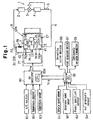
- a refrigerant circuit of a vehicle air conditioner includes a compressor module CPM, which includes a variable displacement compressor CP and a compressor controller 77 connected the compressor CP, and an external refrigerant circuit 1.
- the external refrigerant circuit 1 includes a condenser 2, an expansion valve 3, an evaporator 4, a low pressure pipe 6 for refrigerant gas, which connects the exit of the evaporator 4 to a suction chamber 5 of the compressor CP, and a high pressure pipe 8, which connects a discharge chamber 7 of the compressor CP to the condenser 2.
- a fixed restrictor 8a is provided in the middle of the high pressure pipe 8.
- the fixed restrictor 8a is located between two points at which the pressure is measured and increases the pressure difference.
- the refrigerant gas enters the suction chamber 5 from the evaporator 4 via the low pressure pipe 6.
- the compressor CP draws and compresses the refrigerant gas from the suction chamber 5 and discharges the compressed refrigerant gas to the discharge chamber 7.
- High pressure refrigerant gas in the discharge chamber 7 is supplied to the condenser 2 via the high pressure pipe 8.
- the opening size of the expansion valve 3 is automatically feedback controlled based on the temperature and pressure of the refrigerant.
- a temperature sensing cylinder 9 provided downstream of the evaporator 4 detects the temperature of the refrigerant.
- the expansion valve 3 adjusts the flow rate of refrigerant supplied to the evaporator 4 and also directly adjusts the flow rate of refrigerant in the external refrigerant circuit 1.
- the compressor CP includes a cylinder block 11, a front housing 12, which is secured to the front end face of the cylinder block 11, and a rear housing 14, which is connected to the rear end face of the cylinder block 11 via a valve plate assembly 13.
- a crank chamber 15 is defined between the cylinder block 11 and the front housing 12.
- a drive shaft 16 extends through the crank chamber 15 and is rotatably supported by the cylinder block 11 and the front housing 12 through a bearing.
- a lug plate 17 is located in the crank chamber 15 and is secured to the drive shaft 16.
- a swash plate 18, which is used as a cam plate in this embodiment, is accommodated in the crank chamber 15.
- the swash plate 18 is supported to slide along the axial direction of the drive shaft 16 and to incline with respect to a plane perpendicular to the drive shaft 16.
- a hinge mechanism 19 connects the lug plate 17 to the swash plate 18. The hinge mechanism 19 permits the swash plate 18 to rotate integrally with the lug plate 17 and the drive shaft 16, guides the movement of the swash plate 18 in the axial direction of the drive shaft 16, and guides the inclination of the swash plate 18 with respect the drive shaft 16.
- a plurality of cylinder bores 20 are formed around the axis of the drive shaft 16 in the cylinder block 11.
- a single headed piston 21 is accommodated in each cylinder bore 20.
- the front and rear openings of the cylinder bore 20 are closed by the valve plate assembly 13 and the piston 21, respectively.
- Each piston 21 defines a gas compression chamber in the corresponding cylinder bore 20.
- Each piston 21 is coupled to the swash plate 18 by a pair of shoes 23.
- the swash plate 18 converts rotation of the drive shaft 16 into reciprocation of each piston 21 via the shoes 23.
- the lug plate 17, the swash plate 18, the hinge mechanism 19 and the shoe 23 function as a variable displacement mechanism.
- the drive shaft 16 is coupled to an engine, which serves as an external drive source, via a power transmission mechanism 24.
- the power transmission mechanism 24 includes a belt and a pulley.
- the power transmission mechanism 24 may include a clutch mechanism, such as an electromagnetic clutch, which is capable of engaging or disengaging the compressor by external electric control. In this embodiment, the power transmission mechanism 24 has no clutch mechanism. Therefore, while the engine 25 is running, the compressor is driven continuously.
- a suction chamber 5 and a discharge chamber 7 are defined between the valve plate assembly 13 and the rear housing 14.
- the suction chamber 5 forms a suction pressure zone, the pressure of which is a suction pressure Ps.
- the discharge chamber 7 forms a discharge pressure zone, the pressure of which is a discharge pressure Pd.
- the valve plate assembly 13 has suction ports 26 and suction valves 27, which open and close the ports 26, discharge ports 28 and discharge valves 29, which open and close the ports 28 corresponding to each cylinder bore, respectively.
- the inclination angle of the swash plate 18 changes according to the pressure in the crank chamber 15 (crank pressure Pc).
- the inclination angle of the swash plate 18 determines the stroke of piston 21 or the displacement of the compressor.
- the compressor CP includes a crank pressure control mechanism for controlling the crank pressure Pc.
- the crank pressure control mechanism includes a bleed passage 30, a supply passage 31 and a control valve 32.
- the bleed passage 30 connects the crank chamber 15 to the suction chamber 5 to release refrigerant gas from the crank chamber 15.
- the supply passage 31 connects a second pressure monitoring point P2 in the high pressure pipe 8, which is closer to the condenser 2 than the fixed restrictor 8a, to the crank chamber 15 to conduct the refrigerant gas to the crank chamber 15.
- the supply passage 31 includes a pressure detecting passage 33, which connects the second pressure monitoring point P2 to the control valve 32, and a crank passage 34, which connects the control valve 32 to the crank chamber 15.
- the pressure detecting passage 33 forms an upstream section of the supply passage 31, and the crank passage 34 forms a downstream section of the supply passage 31.
- the control valve 32 adjusts the flow rate of the high pressure refrigerant gas supplied to the crank chamber 15 through the supply passage 31 to control the crank pressure Pc.
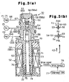
- Fig. 3(a) shows a cross-sectional view of a control valve of the first embodiment of the present invention.
- the control valve 32 includes an inlet valve mechanism 51 and a solenoid 52, which is used as an electromagnetic actuator.
- the inlet valve mechanism 51 adjusts the opening degree of the supply passage 31.
- the solenoid 52 exerts a force according to the level of an electric current, which is applied to the inlet valve mechanism 51, through an operating rod 53.
- the operating rod 53 is cylindrical and has a divider 54, a coupler 55 and a guide 57.
- the end of the guide 57 that is adjacent to the coupler 55 functions as a valve body 56.
- the cross-sectional area of the coupler 55 is smaller than the cross-sectional area S4 of the valve body 56.
- the valve housing 58 of the control valve 32 includes a plug 58a, an upper housing member 58b, which houses the inlet valve mechanism 51, and a lower housing member 58c, which houses the solenoid 52.
- the plug 58a is threaded into the upper housing member 58b to close an upper opening.
- a valve chamber 59 and a through hole 60 connected thereto are defined in the upper housing member 58b.
- a pressure sensing chamber 61 is defined by the upper housing member 58b and the plug 58a.
- the pressure sensing chamber 61 includes a high pressure chamber 65 and a crank pressure chamber 66.
- the through hole 60 connects the pressure sensing chamber 61 to the valve chamber 59.
- the operating rod 53 extends through the valve chamber 59 and the through hole 60 to the pressure sensing chamber 61.
- the operating rod 53 moves axially such that the valve body 56 selectively connects the valve chamber 59 and the through hole 60.
- the crank pressure chamber 66 is always connected to the through hole 60.
- a first radial port 62 is formed in the upper housing member 58b to communicate with the valve chamber 59.
- the valve chamber 59 is connected to the second pressure monitoring point P2 through the first radial port 62 and the pressure detecting passage 33.
- the pressure PdL at the second pressure monitoring point P2 is applied to the valve chamber 59 through the pressure detecting passage 33 and the first port 62.
- a second radial port 63 is formed in the upper housing member 58b to communicate with the crank pressure chamber 66.
- the second radial port 63 connects the crank pressure chamber 66 to the crank chamber 15 through the crank passage 34.
- the first radial port 62, the valve chamber 59, the through hole 60, the crank pressure chamber 66 and the second radial port 63 form a part of the supply passage 31 within the control valve 32.
- the valve body 56 of the operating rod 53 is located in the valve chamber 59.
- the cross-sectional area S3 of the coupler 55 extending within the through hole 60 is smaller than the cross-sectional area S1 of the through hole 60.
- the cross-sectional area S1 of the through hole 60 is smaller than the cross-sectional area S4 of the valve body 56.
- the inner wall of the valve chamber 59, to which the through hole 60 opens functions as a valve seat 64 for receiving the valve body 56.
- the through hole 60 functions as a valve opening, which is selectively opened and closed by the valve body 56. When the valve body 56 contacts the valve seat 64, the through hole 60 is shut off from the valve chamber 59. As shown in Fig. 3, when the valve body 56 is spaced from the valve seat 64, the through hole 60 is connected to the valve chamber 59.
- the divider 54 of the operating rod 53 is fitted in the pressure sensing chamber 61.
- the divider 54 divides the pressure sensing chamber 61 into the high pressure chamber 65 and the crank pressure chamber 66.
- the divider 54 functions as a partition between the high pressure chamber 65 and the crank pressure chamber 66 and does not permit direct connection between both chambers 65 and 66.
- the cross-sectional area S2 of the divider 54, which functions as the partition, is equal to cross-sectional area S1 of the through hole 60. Therefore, the passage within the pressure sensing chamber 61, through which the divider 54 is fitted, is continuous with the through hole 60.
- a third radial port 67 is defined in the upper housing member 58b to communicate with the high pressure chamber 65.
- the high pressure chamber 65 is connected through the third port 67 and the passage 68 to the first pressure monitoring point P1, or the discharge chamber 7.
- the pressure PdH at the first pressure monitoring point P1 is applied through the passage 68 and the third port 67 to the high pressure chamber 65.
- a return spring 69 is contained in the high pressure chamber 65.
- the return spring 69 urges the operating rod 53 to cause the valve body 56 to move away from the valve seat 64.
- the solenoid 52 is provided with a cup-shaped receiving cylinder 71 fixed in the lower housing member 58c.
- a fixed iron core 70 is fitted in the upper opening of the receiving cylinder 71.
- the fixed iron core 70 is a part of the inner wall of the valve chamber 59 and also defines a plunger chamber 72 in the receiving cylinder 71.
- a movable iron core 74 is contained in the plunger chamber 72.
- the fixed iron core 70 includes a guide hole 73, which accommodates the guide 57. A slight clearance (not shown) exists between the inner wall of the guide hole 73 and the guide 57.
- the valve chamber 59 and the plunger chamber 72 communicate with each other through the clearance. Thus, the pressure in the valve chamber 59, or the pressure PdL at the second pressure monitoring point P2, is applied inside the plunger chamber 72.
- the lower end of the guide 57 extends into the plunger chamber 72.
- the movable iron core 74 is fixed to the lower end of the guide 57.
- the movable iron core 74 moves in the axial direction integrally with the operating rod 53.
- a shock absorbing spring 75 is contained in the plunger chamber 72.
- the shock absorbing spring 75 urges the movable iron core 74 and the operating rod 53 toward the fixed iron core 70.
- the force of the shock absorbing spring 75 is less than the force of the return spring 69. Accordingly, when electric power is not supplied to a coil 76, the return spring 69 moves the movable iron core 74 and the operating rod 53 to the initial position as shown in Fig. 3(a), so that the control valve 32 is fully open.
- the coil 76 surrounds the fixed iron core 70 and the movable iron core 74.
- a compressor controller 77 supplies electric power to the coil 76 through a drive circuit 78.
- the coil 76 then generates an electromagnetic force F corresponding to the level of the electric power supplied to the coil 76 between the fixed iron core 70 and the movable iron core 74.
- the electromagnetic force F attracts the movable iron core 74 toward the fixed iron core 70 and urges the valve body 56 towards the valve seat 64.
- Duty control is a method where the ON-time per cycle of a pulsed voltage, which is turned on and off periodically, is adjusted to modify the average value of the applied voltage.
- the average value of the applied voltage can be obtained by multiplying the ratio of the ON-time of the pulsed voltage to the cycle time thereof, i.e., the duty ratio Dt, by the pulsed voltage value.
- the larger the duty ratio Dt is, the smaller the opening degree of the valve is.
- the opening degree of the control valve 32 depends on the axial position of the operating rod 53.
- the axial position of the operating rod 53 is determined based on various forces that act axially on the operating rod 53. These forces will be described referring to Fig. 3(b).
- the downward forces shown in Fig. 3(b) tend to space the valve body 56 from the valve seat 64 (the valve opening direction).
- the upward forces shown in Fig. 3(b) tend to move the valve body 56 toward the valve seat 64 (the valve closing direction).
- the divider 54 receives a downward force f1 from the return spring 69..
- the divider 54 also receives a downward force based on the pressure PdH in the high pressure chamber 65.
- the effective pressure receiving area of the divider 54 with respect to the pressure PdH of the high pressure chamber 65 is equal to the cross-sectional area S2 of the divider 54.
- the divider 54 also receives an upward force based on the pressure in the through hole 60 (crank pressure Pc).
- the effective pressure receiving area of the divider 54 with respect to the pressure Pc in the through hole is equal to the cross-sectional area S2 of the divider 54 minus the cross-sectional area S3 of the coupler 55.
- the guide 57 receives an upward force f2 from the shock absorbing spring 75 and an upward electromagnetic force F from the solenoid 52.
- the guide 57 also receives an upward force based on the pressure PdL in the plunger chamber 72.
- the effective pressure receiving area of the guide 57 with respect to the pressure PdL in the plunger chamber 72 is equal to the cross-sectional area S4 of the guide 57.
- the guide 57 also receives a downward force based on the pressure PdL in the valve chamber 59 and a downward force based on the pressure Pc in the through hole 60.
- the effective pressure receiving area of the guide 57 with respect to the pressure PdL in the valve chamber 59 is equal to the cross-sectional area S4 of the guide 57 minus the cross-sectional area S1 of the through hole 60.
- the effective pressure receiving area of the guide 57 with respect to the pressure Pc in the through hole 60 is equal to the cross-sectional area S1 of the through hole 60 minus the cross-sectional area S3 of the coupler 55.
- the net force ⁇ F2 acting on the guide 57 can be expressed by equation 2.
- the operating rod 53 is integral with the divider 54, the coupler 55 and the guide 57.
- the axial position of the operating rod 53 is a position where the force ⁇ F1 in equation 1 is balanced with the force ⁇ F2 in equation 2.
- PdH ⁇ S2 - PdL ⁇ S1 - Pc(S2-S1) F - f1 + f2
- Equation 4 the (PdH-PdL) on the left side 4 is the pressure difference ⁇ Pd between the two points, that is, the first pressure monitoring point P1 and the second pressure monitoring point P2.
- f1, f2 and S1 are fixed parameters, which are determined by the design of the device.
- the electromagnetic force F is, however, a variable parameter that changes depending on the power supplied to the coil 76. Equation 4 shows that the operating rod 53 operates to change the pressure difference ⁇ Pd in accordance with changes in the electromagnetic force F.
- the operating rod 53 operates in accordance with the pressure PdH and the pressure PdL, which act on the rod 53, such that the pressure difference ⁇ Pd, which is determined by the electromagnetic force F, seeks target, or set pressure difference ⁇ Pd set .
- the operating rod 53 functions as a pressure detecting body together with the valve chamber 59, the plunger chamber 72 and the high pressure chamber 65 and the like.
- the pressure difference ⁇ Pd is expressed the following equation 5 which is a function of the input current for the coil 76.
- ⁇ Pd f(I)
- the position of the operating rod 53, which changes the displacement of the compressor is determined by the pressure difference ⁇ Pd.
- the compressor module CPM includes a suction pressure sensor 41, a discharge pressure sensor 42 and a rotation sensor 43, which function as an information detector.
- the suction pressure sensor 41 detects the suction pressure Ps of the compressor CP
- the discharge pressure sensor 42 detects the discharge pressure Pd of the compressor CP
- the rotation sensor 43 detects the rotational speed Nc (rpm) of the drive shaft 16.
- the suction pressure Ps and discharge pressure Pd of the compressor CP and rotational speed Nc of the drive shaft 16 are sent to a compressor controller 77.
- Tloss is loss torque
- Ps is the suction pressure Ps of the compressor CP.
- the discharge pressure Pd, the rotational speed Nc and the discharge gas flow rate Qd are variables that greatly influence the load torque Tr.
- the suction pressure Ps which has a small effect on the load torque Tr compared with the other variables is used as a variable.
- the pressure difference ⁇ Pd depends on the characteristics of the valve.
- the specific weight ⁇ d of the discharge gas can be approximated using the discharge pressure Pd detected by the discharge pressure sensor 42.
- a fixed restrictor 8a is provided near the compressor CP. Therefore, the pressure difference ⁇ Pd, the restrictor area and the specific weight ⁇ d of the discharge gas can be used to accurately approximate the discharge gas flow rate Qd.
- the compressor controller 77 is an electronic control unit for the compressor including a CPU, a ROM, a RAM and an input-output interface.
- the compressor controller 77 stores equation 6.
- An external controller for example, an air conditioner controller 80
- the compressor controller 77 computes the set pressure difference ⁇ Pd set of the control valve 32, which reflects the discharge gas flow rate Qd corresponding to the set torque Tr set based on equations 6 and 7 to cause the load torque Tr that acts on the drive shaft 16 and the set torque Tr set to coincide based on the torque setting signals. Further, the compressor controller 77 computes the duty ratio Dt necessary for drive signals sent to the coil 76 to adjust the control valve 32 to produce the set pressure difference ⁇ Pd set .
- the compressor controller 77 commands the drive circuit 78, and the drive circuit 78 sends drive signals to the coil 76 at the duty ratio Dt.
- the voltage applied to the coil 76 is changed as required, and the control valve 32 is controlled to produce set pressure difference ⁇ Pd set .
- the external controller produces torque setting signals for the set torque T set to a controller that computes an index. The index controls the control valve from the torque setting signals.
- the external controller is located outside the compressor.
- the air conditioner controller 80 of the vehicle air conditioner shown in Fig. 1 is an electronic control unit including a CPU 80a, a ROM, a RAM and an input-output interface (I/O).
- the input terminal of I/O of the air conditioner controller 80 is connected to a first device for detecting external information that reflects the refrigerant performance required for the refrigerant circuit of an air conditioner.
- the first device includes an air conditioner switch 81, which turns the air conditioner, on and off, a temperature adjuster 82, which sets a target temperature in the passenger compartment of the vehicle, and a passenger compartment temperature sensor 83, which detects the temperature in the passenger compartment.
- the temperature adjuster 82 and the temperature sensor 83 are operated by a passenger in the vehicle.
- the air conditioner controller 80 computes an appropriate discharge refrigerant discharge amount for the compressor based on the ON/Off state of the air conditioner switch 81, the target temperature in the temperature adjuster 82 and the temperature in the passenger compartment temperature sensor 83 and computes the corresponding load torque Tr of the compressor CP from equation 6.
- the air conditioner controller 80 controls the corresponding drive section (not shown) to maintain a desired temperature in the passenger compartment at a target temperature set by the temperature adjuster 82. Then, the drive section adjusts the temperature of air exiting from the air conditioner, air flow, air flow patterns and the like.
- the drive section includes a servo motor, a blower motor, and an air mix door driving servo motor, which drive a door through which internal and external air are exchanged.
- An engine controller 90 is an electronic control unit for an engine, including a CPU, a ROM, a RAM and an input-output interface (I/O).
- the input terminal of I/O of the engine controller 90 is connected to a second device for detecting external information that reflects the load on the engine.
- the second device includes a vehicle speed sensor 91, a rotational speed sensor 92 for detecting the rotational speed Ne of the engine 25, a pedal position sensor 93 for detecting the depression degree of an acceleration pedal (gas pedal) of the vehicle and an air pressure sensor 94 for detecting the pressure of air being drawn into the engine.
- To the output terminal of I/O of the engine controller 90 are connected a continuously variable transmission 95, an electronic control throttle device 96 provided in the intake passage of the engine 25, and a fuel injection device 97.
- the engine controller 90 communicates with the air conditioner controller 80 and receives and sends data signals from and to the air conditioner controller 80.
- the engine controller 90 sends information regarding whether or not the vehicle is in an exceptional control mode, to the air conditioner controller 80.
- the "exceptional control mode” indicates the following modes: a case where the engine 25 is under a high load such as when climbing, a case where the vehicle is being accelerated, such as when overtaking another vehicle, and a case where the engine 25 is being started.
- the air conditioner controller 80 When the air conditioner controller 80 receives the information that a vehicle is in an exceptional mode from the engine controller 90, it sets the lowest torque value as a set torque Tr set , and at other times (non-exceptional mode) the air conditioner controller 80 sets the load torque according to the appropriate discharge gas flow rate Qd as the set torque Tr set . The selective determination of the set torque Tr set in the air conditioner controller 80 will be described.
- the flowchart of Fig. 4 shows the main routine for controlling the compressor CP displacement.
- the air conditioner controller 80 starts processing.
- the air conditioner controller 80 performs various initial settings in step S1.
- step S2 the air conditioner controller 80 waits until the air conditioner switch 81 is turned on. When the air conditioner switch 81 is turned on, the air conditioner controller 80 proceeds to step S3.
- step S3 the air conditioner controller 80 determines whether or not the vehicle is in an exceptional mode from the signals from the engine controller 90. If the outcome of step S3 is positive, the air conditioner controller 80 proceeds to step S4 and performs an exceptional control procedure corresponding to the exceptional mode. In the exceptional control procedure, the air conditioner controller 80 instructs the compressor controller 77 to set the lowest torque value as the set torque Tr set .
- step S3 the air conditioner controller 80 proceeds to step S5 and performs a normal control procedure.
- the air conditioner controller 80 computes the refrigerant discharge amount required for the compressor CP based on information such as the set temperature by the temperature adjuster 82 and the detected temperature from the passenger compartment temperature sensor 83 and the like, and the controller 80 computes the corresponding compressor CP torque Tr. Then, the air conditioner controller 80 instructs the compressor controller 77 to set the computed torque Tr as the set torque Tr set . Further, the air conditioner controller 80 sends the set torque Tr set to the engine controller 90.
- the compressor controller 77 subsequently computes the discharge flow rate Qd corresponding to the torque setting signals instructed from the air conditioner controller 80, computes the pressure difference ⁇ Pd set of the control valve 32 corresponding to the discharge flow rate Qd, and computes the required Duty ratio Dt of the drive signals that is output to the coil 76 to obtain the set pressure difference ⁇ Pd set .
- the drive circuit 78 that received instructions from the compressor controller 77 sends the coil 76 a drive signal according to the duty ratio Dt. Accordingly, the set pressure difference ⁇ Pd set is changed to an appropriate value so that the compressor CP is operated at the set torque Tr set.
- the position of the operating rod 53 (valve body 56) in the control valve 32, that is, the valve opening degree is determined as follows.
- the valve body 56 When the power is supplied to the coil 76, the valve body 56 is positioned with respect to the valve seat 64 so that the upward urging force (F+f2) and the downward urging force f1 are balanced, and the opening degree of the control valve 32 is determined.
- the amount of refrigerant gas conducted to the crank chamber 15 through the supply passage 31 is determined in accordance with the valve opening degree.
- the crank pressure Pc is adjusted by the relationship between the refrigerant gas amount introduced to the crank chamber 15 through the supply passage 31 and the refrigerant gas amount conducted from the crank chamber 15 through the bleed passage 30.
- the difference between the crank pressure Pc and the internal pressure of the compressor 22 is changed according to the change in the crank pressure Pc, and the inclination angle of the swash plate 18 is changed accordingly.
- the stroke of the piston 21, that is, the discharge displacement of the compressor CP is adjusted.
- the opening degree of the control valve 32 is small, the crank pressure Pc decreases and the inclination angle of the swash plate 18 increases. Consequently, the stroke of the piston 21 increases, and the compressor CP is operated at a large discharge displacement.
- the opening degree of the control valve 32 is large, the pressure Pc in the crank chamber 15 increases and the inclination angle of the swash plate 18 decreases. Consequently, the stroke of the piston 21 decreases, and the compressor CP is operated at a small discharge displacement.
- the engine controller 90 calculates the target engine output torque Tr eng by the use of information such as the depression degree of an acceleration pedal from the pedal position sensor 93, the rotational speed Ne of the engine 25 from the rotational speed sensor 92 and the set torque Tr set received from the air conditioner controller 80 and the like.
- the engine controller 90 controls the engine 25 to obtain the target engine output torque Tr eng .
- the engine controller 90 determines the target opening degree or size of the throttle valve based on the target engine output torque Tr eng and executes a command to produce the target opening degree to a throttle device 96.
- the throttle device 96 adjusts the opening degree of a throttle valve (not shown) and thus adjusts the intake air amount.
- the engine controller 90 calculates a target fuel injection amount based on the suction air pressure, from the air pressure sensor 94, and the previously stored theoretical air-fuel ratio and instructs the fuel injection device 97 to produce the target fuel injection amount.
- the fuel injection device 97 injects the target amount of fuel corresponding to the instructed theoretical 'air-fuel ratio into the fuel chamber of the engine 25 in the suction stroke.
- the engine controller 90 determines a target value of the target rotational speed Ne set of the engine 25 based on the target engine output torque Tr eng . Further, the engine controller 90 calculates a target transmission ratio based on the target rotational speed Ne set and the vehicle speed from a vehicle speed sensor 91 and instructs the continuously variable transmission 95 to produce the target transmission ratio.
- the continuously variable transmission 95 adjusts the rotational speed Ne of the engine 25 to the target rotational speed Ne set by adjusting the pulley ratio (effective diameter ratio) of for example the drive pulley to the driven pulley to attain the instructed target transmission ratio.
- the engine 25 is operated by the combination of the engine output torque Tr eng and the rotational speed Ne set from which the optimal fuel efficiency can be obtained.
- the first embodiment has the following advantages.
- the air conditioner controller 80 sends torque setting signals for the set torque Tr set to the compressor controller 77 so that the torque Tr of the compressor CP produces the set torque Tr set . Therefore, the air conditioner controller 80 is able to execute accurate control of the compressor displacement based on torque.
- the air conditioner controller 80 also sends the torque signals for the set torque Tr set to the engine controller 90. Accordingly, when the engine 25 is efficiently controlled based on the value of the load torque Tr of the compressor CP, the engine controller 90 is able to use the set torque Tr set from the air conditioner controller 80 as data concerning the compressor torque and a load torque estimation map is not needed. This simplifies the control of the engine 25. Further, the vehicle air conditioner can be easily applied to various vehicles.
- the controllers 77, 80 and 90 communicate torque information with one another. Therefore, time and effort to convert other signals to torque signals are omitted between the controllers 77, 80 and 90, and the control of the compressor CP displacement and output of the engine 25 become easier.
- the air conditioner controller 80 functions as an external controller that instructs the compressor controller 77 to produce the set torque Tr set . Thus, a special external controller other than the air conditioner controller 80 is not needed, which conserves space.
- the compressor controller 77 computes the set pressure difference ⁇ Pd set of the control valve 32, which corresponds to the set torque Tr set, from equations 6 and 7 and then controls the control valve 32 so that the pressure difference ⁇ Pd of the control valve 32 is steered to the set pressure difference ⁇ Pd set . Since, in the compressor controller 77, the load torque Tr can be accurately estimated in spite of the constitution of the external refrigerant circuit 1 of the vehicle air conditioner, the vehicle air conditioner can be easily applied to various vehicles.
- the suction pressure Ps and discharge pressure Pd of the compressor CP and the rotational speed Nc of the drive shaft 16 are respectively detected by the sensors 41, 42 and 43 provided in the compressor module CPM. Accordingly, all information necessary for controlling the displacement of the compressor CP is collected by an information detector in the compressor module CPM. As a result, it is not necessary to provide an additional information detector outside the compressor module CPM. Accordingly, in the air conditioner, it is possible to combine a different compressor module CPM of another maker with the refrigerant circuit.
- the control valve 32 includes the operating rod 53, which mechanically detects the pressure differences ⁇ Pd across the fixed restrictor 8a.
- the valve opening degree of the control valve 32 is automatically adjusted based on the pressure difference ⁇ Pd detected by the operating rod 53, and the set pressure difference ⁇ Pd set, which is an index for controlling the automatic valve opening degree, is controlled by the amount of current supplied to the coil 76. Therefore, the adjustment of the opening degree of the control valve 32 is rapidly carried out.
- a cylindrical bellows with a bottom 101 which functions as a pressure sensing member, is contained in the high pressure chamber 65.
- the operating rod 53 and the bellows 101 function as first and second pressure difference detectors, respectively.
- the top end of the bellows 101 is fixed to a plug 58a.
- the bellows 101 divides the high pressure chamber 65 into a first pressure chamber 102, which is located inside the bellows 101, and a second pressure chamber 103, which is located outside the bellows 101.
- the bottom wall of the bellows 101 is provided with a hole 101a for receiving the operating rod 53, and the upper end of the divider 54 of the operating rod 53 is inserted into the hole 101a.
- the bellows 101 is mounted in the high pressure chamber 65 in an elastically compressed manner. The bellows is pressed against the divider 54 by a downward force f3 due to this compression through the hole 101a.
- the first pressure chamber 102 is connected to the discharge chamber 7, in which the first pressure monitoring point P1 is located, through a P1 port 104 formed in the plug 58a and a first pressure detecting passage 105.
- the second pressure chamber 103 is connected to the second pressure monitoring point P2 through a radial P2 port 106 and a second pressure detecting passage 107 formed in the upper housing member 58b of the valve housing 58.
- the monitored pressure PdH at the first pressure monitoring point P1 is applied to the first pressure chamber 102 and the monitored pressure PdL at the second pressure monitoring point P2 is applied to the second pressure chamber 103.
- a supply passage 31 connects the first pressure monitoring point P1 to the crank chamber 15.
- An upstream portion of the supply passage 31 connects the first pressure monitoring point P1 to the control valve 32 through the second port 63 and a downstream portion connects the control valve 32 to the crank chamber 15 through the first port 62. That is, in the second embodiment, the direction of refrigerant gas flow through the first and second ports is different from that of the first embodiment.
- a coil-shaped spring 108 is accommodated between the fixed iron core 70 and the movable iron core 74 in the plunger chamber 72.
- the force of the spring 108 separates the movable iron core 74 from the fixed iron core 70, that is, the spring 108 spaces the valve body from the valve seat 64.
- the divider 54 receives a downward force f3 from the bellows 101.
- the divider 54 also receives a downward force based on the difference between the downward force of the pressure PdH in the first pressure chamber 102 and the upward force of the pressure PdL in the second pressure chamber 103.
- the effective receiving pressure area of the bellows 101 with respect to the pressure PdH in the first pressure chamber 102 is equal to the cross-sectional area 55 of the bellows.
- the effective receiving pressure area of the bellows 101 with respect to the pressure PdL in the second pressure chamber 103 is the cross-sectional area 55 minus the cross-sectional area S2 of the divider 54.
- the divider 54 receives a force of PdHxS5-PdL(S5-S2).
- the guide 57 receives a downward force f4 from the spring 108.
- the guide 57 also receives a downward force based on the pressure Pd in the through hole 60.
- the pressure PdH of the crank pressure chamber 66 acts on the guide 57.
- the receiving pressure area of the guide 57 with respect to the pressure PdH in the through hole 60 is the cross-sectional are S1 of the through hole 60 minus the cross-sectional area S3 of the coupler 55.
- the guide 57 further receives an upward force based on the pressure Pc in the valve chamber 59.
- the receiving pressure area of the guide 57 with respect to the pressure Pc in the valve chamber 59 is the cross-sectional area 54 of the guide 57 minus the cross-sectional area S1 of the through hole 60.
- the axial position of the operating rod 53 is defined at a position where ⁇ F1 in equation 8 is equal to ⁇ F2 in equation 9.
- ⁇ F1 ⁇ F2
- equation 10 which follows, can be obtained.
- the control valve 32 of the second embodiment positions the operating rod 53 by a composite effect of a force based on the first pressure difference ⁇ Pd1 (PdH-PdL) and a force based on the second pressure difference ⁇ Pd2 (PdL-Pc). That is, the operating rod 53 is displaced by not only the variation of the first pressure difference ⁇ Pd1 but also by the second pressure difference ⁇ Pd2. As described above, the control valve 32 of the second embodiment positions the operating rod 53 to maintain a constant relationship between the first pressure difference ⁇ Pd1 and the second pressure difference ⁇ Pd2 as determined by the electromagnetic force F.
- the discharge pressure PdL is significantly larger than the crank pressure Pc. Therefore, the second pressure difference ⁇ Pd2 may be approximated to the discharge pressure PdL.
- the operating rod 53 may be positioned by the discharge pressure PdL using the crank pressure Pc on the low pressure side.
- the second embodiment has the following advantages in addition to those of the above-described first embodiment.
- the first pressure difference ⁇ Pd1 which is the pressure difference across the fixed restrictor 8a, substantially reflects the discharge gas flow rate Qd except when the discharge gas flow rate Qd is small.
- the control valve 32 in the second embodiment employs, in addition to the first pressure difference ⁇ Pd1, the second pressure difference ⁇ P2.
- the operating rod 53 is influenced by the second pressure difference ⁇ Pd2, and the operating rod 53 is accurately positioned. This improves the adjustment of the valve opening degree.
- controllers 77, 80 and 90 instead of the separate controllers 77, 80 and 90, one or two controllers, which perform the tasks of these controllers 77, 80 and 90, may be provided.
- the air conditioner controller 80 or the engine controller 90 may perform the functions of the compressor controller 77.
- the torque setting signals are set in the air conditioner controller 80 or the engine controller 90, and torque setting signals are associated with the index for controlling the control valve.
- the CPU memory of the air conditioner controller 80 or the engine controller 90 is increased as required. With such a structure, CPU is localized in the air conditioner controller 80 or the engine controller 90 thereby simplifying the structure of the air conditioner.
- the engine controller 90 may perform the function of the air conditioner controller 80 that controls an engine. Thus, a separate air conditioner controller 80 need not be provided. Additionally, the engine controller 90 may function as an external controller. When the engine controller 90 functions as the external controller, it sends torque setting signals to the compressor controller 77 to control the control valve 32 so that the set torque Tr set is attained. This simplifies a network structure that transmits the control signals between controllers.
- the air conditioner controller 80 stores the last set torque Tr set instead of computing the values of the set torque Tr set sent to the compressor controller 77 from the first every time, and may increase or decrease the value by a predetermined value to be the next set torque Tr set . That is, when the discharge displacement of the compressor CP is small, a predetermined value is added to the last set torque Tr set , and when the discharge displacement of the compressor CP is large, a predetermined value is subtracted from the last set torque Tr set . This simplifies the computation of the set torque Tr set.
- the external controller may be a simple manual adjuster.
- the external controller sets the set Tr set in a simple way instead of computing the set torque Tr set by CPU from conditions relating to the temperature from the temperature adjuster 82 and the passenger compartment temperature sensor 83.
- the set torque Tr set is altered stepwise or continuously and sent to the compressor controller 77 by operation of an adjustment knob that sets the cooling conditions in a manual air conditioner.
- a predetermined minimum set torque Tr set is output to the compressor controller 77 by the instruction from the engine controller 90.
- Signals indicating the set torque Tr set can also be output to the engine controller 90 for computing the target engine output torque Tr eng .
- the engine controller 90 effectively controls the engine 25 based on the operating conditions of the compressor CP without mounting a CPU on the air conditioner controller 80.
- the rotational speed Nc of the drive shaft 16 may be computed in the rotational speed sensor 92 instead of detecting the rotation sensor 43 in the compressor module CPM. As a result, the rotation sensor is not needed and the constitution of the compressor module becomes simple and the cost is reduced.
- the engine controller 90 receives the torque signals regarding the set torque Tr set from the air conditioner controller 80. After that, the engine controller 90 judges whether the vehicle is in a normal mode or in an exceptional mode. Then, as described with reference to Fig. 4, when the vehicle is in an exceptional mode, the set torque Tr set is changed to give priority to the vehicle travel, and the torque setting signals regarding the changed set torque Tr set may be sent to the compressor controller 77. Even if the vehicle is in an exceptional mode, the engine controller 90 need not necessarily be operated at the minimum displacement of the compressor CP, and the maximum torque in the allowable range that can be applied to the compressor CP may be the set torque Tr set of the compressor CP. As a result, the control time can be shortened and the air conditioner can be efficiently operated.
- the compressor controller 77 may output signals concerning the load torque value Tr to the engine controller 90. In this case, the receipt of the torque setting signal regarding the set torque Tr set by the compressor controller 77 and control of the control valve 32 is delayed. However, the engine controller 90 is able to compute the target engine output torque Tr eng by using the actual load torque Tr, which is more accurate than the set torque Tr set . Accordingly, the engine 25 can be further efficiently controlled.
- An external controller other than the air conditioner controller 80 and the engine controller 90 may be provided.
- the external controller judges whether any one of the operation torque values, which both the air conditioner controller 80 and the engine controller 90 respectively require of the compressor module CPM, is preceded, and sents the compressor controller 77 the set torque Tr set .
- the compressor controller 77 is located at the . suction pressure zone or near the suction pressure zone of the compressor CP. As a result, the compressor controller 77 is cooled by the suction refrigerant, the temperature of which is comparatively low.
- the load torque Tr of the compressor CP may be reduced regardless of the set torque Tr set instructed from the air conditioner controller 80.
- the pressure of the second pressure difference ⁇ P2 may be the suction pressure Ps, which is lower than the crank pressure Pc, in place of the crank pressure Pc.
- the effect of the discharge pressure PdL becomes more predominant and the adjustment of the valve opening degree in a case where the discharge gas flow rate Qd is low, is further improved.
- the discharge pressure sensor 42 of the compressor module CPM which detects the discharge pressure Pd, may be removed to fix the value of the discharge pressure Pd in equation 6.
- the reason why the discharge pressure Pd need not be used as a variable in equation 6 is that, in the second embodiment, the input current value I into the coil 76 is expressed by a fixed relationship between the first pressure difference ⁇ Pd1, which is reflected by the discharge gas flow rate Qd, and the second pressure difference ⁇ Pd2, which is controlled by the discharge pressure PdL.
- the control valve 32 may be a so-called discharge side control valve that controls the opening degree of the bleed passage 30 instead of adjusting the opening degree of the supply passage 31.
Landscapes
- Engineering & Computer Science (AREA)
- Mechanical Engineering (AREA)
- Physics & Mathematics (AREA)
- Thermal Sciences (AREA)
- General Engineering & Computer Science (AREA)
- Control Of Positive-Displacement Pumps (AREA)
- Compressors, Vaccum Pumps And Other Relevant Systems (AREA)
- Control Of Vehicle Engines Or Engines For Specific Uses (AREA)
- Air-Conditioning For Vehicles (AREA)
Claims (16)
- Kältemittelkreislauf einer Kraftfahrzeugklimaanlage mit einem Verdrängungssteuergerät zum Steuern der Auslassverdrängung eines Kompressors mit variabler Verdrängung, wobei der Kompressor (CP) in den Kältemittelkreislauf eingegliedert ist und eine Antriebswelle (16) hat, wobei ein Lastdrehmoment (Tr) auf die Antriebswelle (16) aufgebracht wird, indem die Antriebswelle (16) von einer externen Antriebsquelle (25) angetrieben wird, und wobei eine Änderung in dem Lastdrehmoment (Tr) eine Änderung in der Auslassverdrängung wiedergibt, wobei das Verdrängungssteuergerät folgendes aufweist:ein Steuerventil (32) zum Ändern der Verdrängung des Kompressors (CP) durch Ändern des Ventilöffnungsgrads;eine erste Steuereinheit, die außerhalb des Kompressors (CP) vorgesehen ist, zum Senden eines Drehmomenteinstellsignals, welches ein Solldrehmoment (Trset) zum Steuern der Auslassverdrängung des Kompressors (CP) anzeigt; undeine zweite Steuereinheit (77, 80, 90) zum Empfangen des von der ersten Steuereinheit gesendeten Drehmomenteinstellsignals, wobei die zweite Steuereinheit (77, 80, 90) einen Index zum Ändern des Öffnungsgrads des Steuerventils auf Grundlage des Drehmomenteinstellventils berechnet, so dass der Steuerventilöffnungsgrad zum Ändern der Verdrängung des Kompressors (CP) gesteuert wird, und, als Ergebnis, wird das Lastdrehmoment (Tr) des Kompressors (CP) auf das Solldrehmoment (Trset) geändert, wobei der Kältemittelkreislauf dadurch gekennzeichnet ist, dassder Druckunterschied (ΔPd) zwischen den Drücken an zwei Drucküberwachungspunkten (P1, P2) in dem Kältemittelkreislauf das Lastdrehmoment wiedergibt, wobei der Öffnungsgrad durch Ändern des Druckunterschieds (ΔPd) auf einen Solldruckunterschied (Δpdset) geändert wird, der dem Solldrehmoment (Trset).
- Kältemittelkreislauf gemäß Anspruch 1, dadurch gekennzeichnet, dass die zweite Steuereinheit (77, 80, 90) eine an dem Kompressor (CP) montierte Kompressorsteuereinheit ist.
- Kältemittelkreislauf gemäß Anspruch 1 oder 2, dadurch gekennzeichnet, dass das Verdrängungssteuerungsgerät ferner eine Klimaanlagensteuereinheit (80) zum Steuern der Klimaanlage und eine Erfassungsvorrichtung (81, 82, 83) aufweist, die an der Klimaanlagensteuereinheit (80) angeschlossen ist, um die die von dem Kältemittelkreislauf der Klimaanlage erforderliche Kältemittelleistung betreffenden Informationen zu erfassen, wobei die Klimaanlagensteuereinheit (80) das Solldrehmoment (Trset) auf Grundlage dieser Information bestimmt.
- Kältemittelkreislauf gemäß Anspruch 2 oder 3, dadurch gekennzeichnet, dass die externe Antriebsquelle (25) eine Kraftmaschine (25) ist und das Verdrängungssteuergerät eine Kraftmaschinensteuereinheit (90) zum Steuern der Kraftmaschine (25) aufweist, wobei auch die erste Steuereinheit das Drehmomenteinstellsignal zu der Kraftmaschinensteuereinheit (90) sendet.
- Kältemittelkreislauf gemäß Anspruch 3, dadurch gekennzeichnet, dass die externe Antriebsquelle (25) eine Kraftmaschine (25) ist und das Verdrängungssteuergerät folgendes aufweist:eine Kraftmaschinensteuereinheit (90) zum Steuern der Kraftmaschine (25); undeine zweite Erfassungsvorrichtung (91, 92, 93, 94), die an die Kraftmaschinensteuereinheit (90) angeschlossen ist, um die eine auf eine Kraftmaschine (25) aufgebrachte Last betreffende Information zu erfassen, wobei ein zweites Solldrehmoment (Trset) auf Grundlage der durch die zweite Erfassungsvorrichtung (91, 92, 93, 94) erfassten Information durch die Kraftmaschinensteuereinrichtung (90) bestimmte wird, wobei die erste Steuereinheit das Drehmomenteinstellsignal auf Grundlage des ersten Solldrehmoments and des zweiten Solldrehmoments (Trset) bestimmt.
- Kältemittelkreislauf gemäß Anspruch 5, dadurch gekennzeichnet, dass die erste Steuereinheit die Klimaanlagensteuereinheit (80) oder die Kraftmaschinensteuereinheit (90) ist.
- Verdrängungssteuerverfahren zum Steuern der Verdrängung eines Kompressors mit variabler Verdrängung, wobei der Kompressor (CP) in eine Kältemittelkreislauf einer Kraftfahrzeugklimaanlage eingegliedert ist und eine Antriebswelle (16) hat, wobei ein Lastdrehmoment auf die Antriebswelle (16) aufgebracht wird, indem die Antriebswelle von einer externen Antriebsquelle (25) angetrieben wird, und wobei eine Änderung des Lastdrehmoments (Tr) eine Änderung in der Auslassverdrängung wiedergibt, wobei das Verfahren folgendes aufweist:Bestimmen eines Solldrehmoments (Trset) zum Steuern der Verdrängung des Kompressors (CP) außerhalb des Kompressors (CP);Übertragen eines Drehmomenteinstellsignals, das das Solldrehmoment (Trset) anzeigt, zu dem Kompressor (CP); undÄndern des Lastdrehmoments (Tr) auf das Solldrehmoment (Trset), indem die Auslassverdrängung des Kompressors (CP) auf Grundlage des Drehmomenteinstellsignals gesteuert wird, wobei das Verfahren dadurch gekennzeichnet ist, dass der Schritt, in dem das Lastdrehmoment (Tr) auf das Solldrehmoment (Trset) geändert wird, folgendes aufweist:Erfassen eines Druckunterschieds (ΔPd) zwischen den Drücken an zwei Drucküberwachungspunkten (P1, P2) in dem Kältemittelkreislauf, wobei der Druckunterschied (ΔPd) das Lastdrehmoment (Tr) wiedergibt; undÄndern des Druckunterschieds (ΔPd) zwischen den zwei Drucküberwachungspunkten (P1, P2) auf einen Solldruckunterschied (ΔPdset), wobei der Solldruckunterschied (ΔPdset) dem Solldrehmoment (Trset) entspricht.
- Verdrängungssteuerverfahren zum Steuern der Auslassverdrängung eines Kompressors mit variabler Verdrängung, wobei der Kompressor (CP) in eine Kältemittelkreislauf einer Kraftfahrzeugklimaanlage eingegliedert ist und eine Antriebswelle (16) hat, wobei ein Lastdrehmoment auf die Antriebswelle (16) aufgebracht wird, indem die Antriebswelle (16) von einer externen Antriebsquelle (25) angetrieben wird, und wobei eine Änderung des Lastdrehmoments (Tr) eine Änderung in der Auslassverdrängung wiedergibt, wobei das Verfahren folgendes aufweist:Bestimmen eines Solldrehmoments (Trset) zum Steuern der Verdrängung des Kompressors (CP) außerhalb des Kompressors (CP);Übertragen eines Drehmomenteinstellsignals, das das Solldrehmoment (Tr) anzeigt, zu dem Kompressor (CP); undÄndern des Lastdrehmoments (Tr) auf das Solldrehmoment (Trset), indem die Auslassverdrängung des Kompressors (CP) auf Grundlage des Drehmomenteinstellsignals gesteuert wird; wobei das Verfahren dadurch gekennzeichnet ist, dass der Schritt, in dem das Lastdrehmoment (Tr) auf das Solldrehmoment (Trset) geändert wird, folgendes aufweist:Erfassen eines ersten Druckunterschieds (ΔPd1) zwischen den Drücken an zwei Drucküberwachungspunkten (P1, P2) in dem Kältemittelkreislauf;Erfassen eines zweiten Druckunterschieds (ΔPd2), der sich von dem ersten Druckunterschied (ΔPd1) unterscheidet, zwischen zwei Drucküberwachungspunkten (7, 15), wobei der erste und der zweite Druckunterschied (ΔPd1, ΔPd2) das Lastdrehmoment (Tr) wiedergeben; undÄndern des ersten und des zweiten Druckunterschieds (ΔPd1, ΔPd2) auf den Solldruckunterschied (ΔPdset), wobei der Solldruckunterschied (ΔPdset) dem Solldrehmoment (Trset) entspricht.
- Verfahren gemäß Anspruch 7 oder 8, dadurch gekennzeichnet, dass das Solldrehmoment (Trset) auf Grundlage von der die für die Klimaanlage erforderliche Kältemittelleistung betreffenden Information oder der die auf die externe Antriebsquelle (25) aufgebrachte Last betreffenden Information bestimmt wird.
- Verfahren gemäß einem der Ansprüche 7 bis 9, dadurch gekennzeichnet, dass das Verfahren ferner das Berechnen der durch den Kompressor (CP) unter Verwendung des Solldrehmoments (Trset) aufgebrachten Last (Treng) aufweist.
- Kältemittelkreislauf einer Fahrzeugklimaanlage mit:einem Kompressor (CP), wobei der Kompressor (CP) eine Antriebswelle (16) hat, auf die durch eine externe Antriebsquelle (25) ein Lastdrehmoment (Tr) aufgebracht wird;einem Steuerventil (32), das sich in dem Kompressor (CP) befindet, um die Auslassverdrängung des Kompressors (CP) durch Steuern des Ventilöffnungsgrads zu ändern;einer Kompressorsteuereinheit (77), die an dem Kompressor (CP) montiert ist, wobei die Kompressorsteuereinheit (77) ein ein Solldrehmoment (Trset) anzeigendes Drehmomenteinstellsignal von außerhalb des Kompressors empfängt, wobei die Kompressorsteuereinheit (77) einen Index zum Ändern des Steuerventilöffnungsgrads auf Grundlage des Drehmomenteinstellsignals berechnet, so dass das Lastdrehmoment (Tr) auf das Solldrehmoment (Trset) geändert wird, wobei die Kompressorsteuereinheit (77) gemäß dem Index eine Anweisung zu dem Steuerventil (32) schickt, und als Ergebnis der Steuerventilöffnungsgrad so gesteuert wird, dass die Verdrängung des Kompressors gesteuert wird, wobei das Kompressormodul dadurch gekennzeichnet ist,dass der Druckunterschied (ΔPd) zwischen den Drücken an zwei Drucküberwachungspunkten (P1, P2) in dem Kältemittelkreislauf das Lastdrehmoment wiedergibt, wobei der Öffnungsgrad durch Ändern des Druckunterschieds (ΔPd) auf einen Solldruckunterschied (ΔPdset) geändert wird, der dem Solldrehmoment (Tr) entspricht.
- Kältemittelkreislauf gemäß Anspruch 11, dadurch gekennzeichnet, dass der Kompressor ferner folgendes aufweist:wobei ein Steuerventil (32) den Druck (Pc) in der Kurbelkammer (15) durch Anpassen des Ventilöffnungsgrads steuert und die Kompressorsteuereinheit (77) eine Gleichung verwendet, die ein Verhältnis zwischen einer Vielzahl von Variablen und dem Solldrehmoment (Trset) verwendet, um den Index des Ventilöffnungsgrads für das Solldrehmoment (Trset) zu berechnen, und die Variablen den Auslassdruck (Pd) des Kompressors (CP), die Drehzahl (Nc) der Antriebswelle (16) und die Auslassgasströmungsrate (Qd) beinhalten.eine Kurbelkammer (15), durch die die Antriebswelle (16) passt;eine Steuerscheibe (18), die mit Bezug auf die Antriebswelle (16) geneigt ist und sich einstückig mit der Antriebswelle (16) in der Kurbelkammer (15) dreht; undeinen Kolben (21), der wirkverbunden mit der Steuerscheibe (18) gekoppelt ist, wobei sich der Kolben (21) in einer Kompressionskammer (22) hin- und herbewegt, wobei der Hub des Kolbens (21) eine Kompressorverdrängung wiedergibt und durch eine Änderung der Neigung der Steuerscheibe (18) in Übereinstimmung mit dem Druck der Kurbelkammer (15) geändert wird;
- Kältemittelkreislauf gemäß Anspruch 12, dadurch gekennzeichnet, dass der Kompressor ferner eine Informationserfassungseinrichtung (41, 42, 43) zum Bestimmen von Werten der Variablen aufweist.
- Kältemittelkreislauf gemäß Anspruch 12, dadurch gekennzeichnet, dass die Variablen den Ansaugdruck (Ps) beinhalten.
- Kältemittelkreislauf gemäß Anspruch 12, dadurch gekennzeichnet, dass der Kältemittelkreislauf einen Kondensator (2) hat, der durch ein Hochdruckrohr (8) an dem Kompressor (CP) angeschlossen ist, und der Kompressor (CP) ein Kältemittelgas durch eine Kompressionskammer (22) in Übereinstimmung mit dem Takt des Kolbens (21) auslässt, und der Kompressor (CP) eine an das Hochdruckrohr (8) angeschlossene Auslasskammer (7) hat, wobei sich das Hochdruckrohr (8) zwischen der Auslasskammer (7) und dem Kondensator (2) befindet, wobei sich in dem Hochdruckrohr (8) eine Drossel (8a) befindet, und das Steuerventil (32) eine Druckunterschiederfassungseinrichtung zum mechanischen Erfassen des Druckunterschieds (ΔPd) zwischen den Drücken über der Drossel (8a) hat, wobei der Ventilöffnungsgrad auf Grundlage des durch die Druckunterschiederfassungseinrichtung erfassten Druckunterschieds (ΔPd) angepasst wird.
- Kältemittelkreislauf gemäß Anspruch 15, dadurch gekennzeichnet, dass der Druckunterschied (ΔPd) ein erster Druckunterschied (ΔPd1) ist und die Druckunterschiederfassungseinrichtung eine erste Druckunterschiederfassungseinrichtung (53) ist, wobei das Steuerventil (32) eine zweite Druckunterschiederfassungseinrichtung (101) zum mechanischen Erfassen eines zweiten Druckunterschieds (ΔPd2) hat, der sich von dem ersten Druckunterschied (ΔPd1) unterscheidet, wobei der Ventilöffnungsgrad durch ein unveränderliches Verhältnis zwischen dem ersten Druckunterschied (ΔPd1) und dem zweiten Druckunterschied (ΔPd2) angepasst wird, wobei der zweite Druckunterschied (ΔPd2) auf dem Auslassdruck (Pd) basiert.
Applications Claiming Priority (4)
| Application Number | Priority Date | Filing Date | Title |
|---|---|---|---|
| JP2000051575 | 2000-02-28 | ||
| JP2000051575 | 2000-02-28 | ||
| JP2000342177A JP4221893B2 (ja) | 2000-02-28 | 2000-11-09 | 容量可変型圧縮機の容量制御装置及び圧縮機モジュール |
| JP2000342177 | 2000-11-09 |
Publications (3)
| Publication Number | Publication Date |
|---|---|
| EP1127721A2 EP1127721A2 (de) | 2001-08-29 |
| EP1127721A3 EP1127721A3 (de) | 2002-04-24 |
| EP1127721B1 true EP1127721B1 (de) | 2003-10-08 |
Family
ID=26586239
Family Applications (1)
| Application Number | Title | Priority Date | Filing Date |
|---|---|---|---|
| EP01104795A Expired - Lifetime EP1127721B1 (de) | 2000-02-28 | 2001-02-27 | Vorrichtung und Verfahren zur Regelung der Fördermenge eines Kompressors mit variabler Verdrängung und Kompressormodul |
Country Status (4)
| Country | Link |
|---|---|
| US (1) | US6484520B2 (de) |
| EP (1) | EP1127721B1 (de) |
| JP (1) | JP4221893B2 (de) |
| DE (1) | DE60100911T2 (de) |
Families Citing this family (59)
| Publication number | Priority date | Publication date | Assignee | Title |
|---|---|---|---|---|
| DE10106243A1 (de) * | 2001-01-31 | 2002-08-01 | Behr Gmbh & Co | Verfahren zur Regelung eines Kompressors |
| JP2002276557A (ja) * | 2001-03-22 | 2002-09-25 | Toyota Industries Corp | 圧縮機トルク算出方法及び空調装置並びにエンジン制御装置 |
| JP2003013863A (ja) * | 2001-06-29 | 2003-01-15 | Toyota Industries Corp | 容量可変型圧縮機の容量制御装置 |
| JP4682474B2 (ja) * | 2001-07-25 | 2011-05-11 | 株式会社デンソー | 流体ポンプ |
| JP4092896B2 (ja) * | 2001-09-14 | 2008-05-28 | スズキ株式会社 | 車両用空調装置の制御装置 |
| JP3741022B2 (ja) * | 2001-10-15 | 2006-02-01 | 株式会社豊田自動織機 | 車両用空調装置 |
| JP2003129956A (ja) | 2001-10-22 | 2003-05-08 | Toyota Industries Corp | 可変容量圧縮機および該可変容量圧縮機を備えた空調装置、可変容量圧縮機における容量制御方法 |
| JP3818136B2 (ja) * | 2001-11-27 | 2006-09-06 | 株式会社豊田自動織機 | 空調装置 |
| JP3818137B2 (ja) | 2001-11-27 | 2006-09-06 | 株式会社豊田自動織機 | 空調装置 |
| JP4162419B2 (ja) * | 2002-04-09 | 2008-10-08 | サンデン株式会社 | 可変容量圧縮機 |
| JP4118587B2 (ja) | 2002-04-09 | 2008-07-16 | サンデン株式会社 | 可変容量圧縮機 |
| US6588222B1 (en) * | 2002-05-08 | 2003-07-08 | Delphi Technologies, Inc. | Low-cost energy-efficient vehicle air conditioning system |
| JP4130566B2 (ja) * | 2002-09-25 | 2008-08-06 | 株式会社テージーケー | 可変容量圧縮機用容量制御弁 |
| FR2845035B1 (fr) * | 2002-09-27 | 2004-12-24 | Valeo Climatisation | Installation de climatisation comprenant un dispositif electronique de controle |
| JP4083561B2 (ja) * | 2002-12-19 | 2008-04-30 | カルソニックカンセイ株式会社 | 車両用空調装置 |
| US6959558B2 (en) * | 2003-03-06 | 2005-11-01 | American Power Conversion Corp. | Systems and methods for head pressure control |
| US6694764B1 (en) * | 2003-03-21 | 2004-02-24 | Delphi Technologies, Inc. | Air conditioning system with electric compressor |
| JP2005016309A (ja) | 2003-06-23 | 2005-01-20 | Sanden Corp | 冷凍サイクルにおける圧縮機トルク算出装置およびそれを用いた制御装置 |
| JP2005016352A (ja) | 2003-06-24 | 2005-01-20 | Sanden Corp | 圧縮機出力算出装置およびそれを用いた制御装置 |
| US6955057B2 (en) * | 2003-06-30 | 2005-10-18 | Carrier Corporation | Control scheme and method for dehumidification systems at low ambient conditions |
| JP2005212543A (ja) * | 2004-01-28 | 2005-08-11 | Sanden Corp | 圧縮機制御装置 |
| US7412842B2 (en) | 2004-04-27 | 2008-08-19 | Emerson Climate Technologies, Inc. | Compressor diagnostic and protection system |
| DE102004029166A1 (de) * | 2004-06-17 | 2005-12-29 | Behr Gmbh & Co. Kg | Verfahren und Vorrichtung zur Regelung eines Kältemittelkreislaufs einer Klimaanlage für ein Fahrzeug |
| US7275377B2 (en) | 2004-08-11 | 2007-10-02 | Lawrence Kates | Method and apparatus for monitoring refrigerant-cycle systems |
| DE102004057159A1 (de) * | 2004-11-26 | 2006-06-01 | Volkswagen Ag | Klimaanlage für ein Kraftfahrzeug |
| JP4580816B2 (ja) | 2005-05-25 | 2010-11-17 | カルソニックカンセイ株式会社 | 可変容量コンプレッサのトルク算出装置およびトルク算出方法 |
| JP2007099225A (ja) * | 2005-10-07 | 2007-04-19 | Denso Corp | 車両の自動走行制御装置 |
| US7611335B2 (en) * | 2006-03-15 | 2009-11-03 | Delphi Technologies, Inc. | Two set-point pilot piston control valve |
| DE102006012749A1 (de) * | 2006-03-17 | 2007-09-20 | Behr Gmbh & Co. Kg | Kraftfahrzeug-Klimaanlage mit Standklimatisierung und Verfahren zum Betreiben einer solchen |
| US7420292B2 (en) * | 2006-04-13 | 2008-09-02 | Eaton Corporation | Vehicle bus control system |
| US8590325B2 (en) | 2006-07-19 | 2013-11-26 | Emerson Climate Technologies, Inc. | Protection and diagnostic module for a refrigeration system |
| US20080216494A1 (en) | 2006-09-07 | 2008-09-11 | Pham Hung M | Compressor data module |
| US8555665B2 (en) * | 2007-03-20 | 2013-10-15 | Volvo Technology Corporation | Method for operating a variable displacement compressor and system with a variable displacement compressor |
| US20090037142A1 (en) | 2007-07-30 | 2009-02-05 | Lawrence Kates | Portable method and apparatus for monitoring refrigerant-cycle systems |
| JP5013189B2 (ja) * | 2007-08-27 | 2012-08-29 | 株式会社デンソー | 車両用空調装置 |
| JP2009063179A (ja) * | 2007-09-04 | 2009-03-26 | Sanden Corp | 圧縮機の駆動トルク演算装置及び可変容量圧縮機の容量制御システム |
| US8393169B2 (en) | 2007-09-19 | 2013-03-12 | Emerson Climate Technologies, Inc. | Refrigeration monitoring system and method |
| US9140728B2 (en) | 2007-11-02 | 2015-09-22 | Emerson Climate Technologies, Inc. | Compressor sensor module |
| US8160827B2 (en) | 2007-11-02 | 2012-04-17 | Emerson Climate Technologies, Inc. | Compressor sensor module |
| JP2011246083A (ja) * | 2010-05-31 | 2011-12-08 | Suzuki Motor Corp | 車両用空調装置 |
| EP2681497A4 (de) | 2011-02-28 | 2017-05-31 | Emerson Electric Co. | Hvac-überwachung und diagnose für haushaltsanwendungen |
| US9272602B2 (en) * | 2011-09-23 | 2016-03-01 | Ford Global Technologies, Llc | Method for controlling vehicle climate control system load |
| US9885508B2 (en) | 2011-12-28 | 2018-02-06 | Carrier Corporation | Discharge pressure calculation from torque in an HVAC system |
| US8964338B2 (en) | 2012-01-11 | 2015-02-24 | Emerson Climate Technologies, Inc. | System and method for compressor motor protection |
| US9480177B2 (en) | 2012-07-27 | 2016-10-25 | Emerson Climate Technologies, Inc. | Compressor protection module |
| US9310439B2 (en) | 2012-09-25 | 2016-04-12 | Emerson Climate Technologies, Inc. | Compressor having a control and diagnostic module |
| CA2904734C (en) | 2013-03-15 | 2018-01-02 | Emerson Electric Co. | Hvac system remote monitoring and diagnosis |
| US9551504B2 (en) | 2013-03-15 | 2017-01-24 | Emerson Electric Co. | HVAC system remote monitoring and diagnosis |
| US9803902B2 (en) | 2013-03-15 | 2017-10-31 | Emerson Climate Technologies, Inc. | System for refrigerant charge verification using two condenser coil temperatures |
| WO2014165731A1 (en) | 2013-04-05 | 2014-10-09 | Emerson Electric Co. | Heat-pump system with refrigerant charge diagnostics |
| DE102013222571A1 (de) * | 2013-11-06 | 2015-05-07 | MAHLE Behr GmbH & Co. KG | Sensoranordnung |
| US9320171B2 (en) * | 2014-06-05 | 2016-04-19 | Toyota Motor Engineering & Manufacturing North America, Inc. | Two-phase cooling systems, power electronics modules, and methods for extending maximum heat flux |
| US10507707B2 (en) * | 2015-06-12 | 2019-12-17 | Ford Global Technologies, Llc | Controlling HVAC compressor speed in a vehicle |
| CN106948954A (zh) * | 2017-05-19 | 2017-07-14 | 重庆超力高科技股份有限公司 | 扭矩控制装置及扭矩控制方法、汽车扭矩控制系统 |
| US11097600B2 (en) * | 2017-08-25 | 2021-08-24 | Thermo King Corporation | Method and system for adaptive power engine control |
| CN107939660B (zh) * | 2017-11-22 | 2023-12-15 | 北京航天石化技术装备工程有限公司 | 一种往复式压缩机气量无级调节系统 |
| KR102896226B1 (ko) * | 2021-04-14 | 2025-12-08 | 두원중공업(주) | 용량 가변형 사판식 압축기 |
| CN113357135B (zh) * | 2021-07-13 | 2023-03-28 | 奇瑞商用车(安徽)有限公司 | 一种变排量压缩机扭矩补偿方法 |
| CN118920958B (zh) * | 2024-10-10 | 2025-02-14 | 中联重科股份有限公司 | 电缸控制方法、装置、电动作业机械及机器可读存储介质 |
Family Cites Families (11)
| Publication number | Priority date | Publication date | Assignee | Title |
|---|---|---|---|---|
| JPH01175517A (ja) | 1987-12-28 | 1989-07-12 | Diesel Kiki Co Ltd | 車輌用空気調和装置 |
| EP0531089B1 (de) | 1991-09-02 | 1997-02-05 | Sanden Corporation | Fahrzeugklimaanlage mit einem, eine fremdgesteuert einstellbare Verdrängungseinrichtung aufweisenden, Kühlflüssigkeitskompressor |
| JP2988057B2 (ja) * | 1991-10-09 | 1999-12-06 | 株式会社デンソー | 可変容量コンプレッサの駆動トルク検出装置 |
| US5285649A (en) * | 1991-10-09 | 1994-02-15 | Nippondenso Co., Ltd. | Method and apparatus for calculating torque of variable capacity type compressor |
| US5199272A (en) * | 1992-06-04 | 1993-04-06 | Nippondenso Co., Ltd. | Idling speed control system |
| JP3355002B2 (ja) | 1993-10-15 | 2002-12-09 | 株式会社豊田自動織機 | 可変容量型圧縮機用制御弁 |
| DE19642832C1 (de) | 1996-10-17 | 1997-09-18 | Daimler Benz Ag | Verfahren zur Steuerung eines Kompressors einer Kraftfahrzeug-Klimaanlage |
| FR2754773B1 (fr) | 1996-10-21 | 1998-11-27 | Renault | Procede de controle du couple d'entree d'une transmission |
| JP3585148B2 (ja) * | 1996-12-16 | 2004-11-04 | 株式会社豊田自動織機 | 可変容量圧縮機用制御弁 |
| JP3817328B2 (ja) | 1997-04-11 | 2006-09-06 | カルソニックカンセイ株式会社 | 可変容量コンプレッサ制御装置 |
| JP3329275B2 (ja) * | 1997-10-07 | 2002-09-30 | 株式会社デンソー | 車両用空調装置 |
-
2000
- 2000-11-09 JP JP2000342177A patent/JP4221893B2/ja not_active Expired - Lifetime
-
2001
- 2001-02-27 US US09/794,807 patent/US6484520B2/en not_active Expired - Lifetime
- 2001-02-27 EP EP01104795A patent/EP1127721B1/de not_active Expired - Lifetime
- 2001-02-27 DE DE60100911T patent/DE60100911T2/de not_active Expired - Lifetime
Also Published As
| Publication number | Publication date |
|---|---|
| US20010017036A1 (en) | 2001-08-30 |
| DE60100911T2 (de) | 2004-09-02 |
| JP2001317467A (ja) | 2001-11-16 |
| JP4221893B2 (ja) | 2009-02-12 |
| US6484520B2 (en) | 2002-11-26 |
| EP1127721A2 (de) | 2001-08-29 |
| EP1127721A3 (de) | 2002-04-24 |
| DE60100911D1 (de) | 2003-11-13 |
Similar Documents
| Publication | Publication Date | Title |
|---|---|---|
| EP1127721B1 (de) | Vorrichtung und Verfahren zur Regelung der Fördermenge eines Kompressors mit variabler Verdrängung und Kompressormodul | |
| EP1111238B1 (de) | Motorregelung für ein Fahrzeug mit Klimaanlage | |
| US6481225B2 (en) | Air conditioning apparatus for vehicle and its control method | |
| US6434956B1 (en) | Control valve and method for controlling an air-conditioning system | |
| US6453685B2 (en) | Control apparatus and control method for variable displacement compressor | |
| US6385979B2 (en) | Displacement control apparatus and method for variable displacement compressor | |
| EP1437245B1 (de) | Einrichtung zum Schätzen von einem Kompressordrehmoments, Motorsteuerung und Verfahren zur Schätzung des Kompressordrehmoments | |
| EP1101639B1 (de) | Klimatisierungsvorrichtung | |
| EP1095804B1 (de) | Klimaanlage | |
| US6371734B1 (en) | Control valve for variable displacement compressor | |
| US6557360B2 (en) | Compressor torque computing method, air-conditioning system and engine control apparatus | |
| EP1122430A2 (de) | Regler für einen Verdichter variabler Verdrängung | |
| US6382926B2 (en) | Control valve in variable displacement compressor | |
| US6519960B2 (en) | Air conditioner | |
| EP1116882A2 (de) | Verdichter mit variabler Verdrängung und Klimaanlage | |
| US6705102B2 (en) | Vehicular air-conditioner | |
| EP1253033A2 (de) | Fahrzeugklimaanlage und Verfahren zur Steuerung einer Fahrzeugklimaanlage | |
| US20020152763A1 (en) | Control device of variable displacement compressor |
Legal Events
| Date | Code | Title | Description |
|---|---|---|---|
| PUAI | Public reference made under article 153(3) epc to a published international application that has entered the european phase |
Free format text: ORIGINAL CODE: 0009012 |
|
| 17P | Request for examination filed |
Effective date: 20010227 |
|
| AK | Designated contracting states |
Kind code of ref document: A2 Designated state(s): DE FR IT Kind code of ref document: A2 Designated state(s): AT BE CH CY DE DK ES FI FR GB GR IE IT LI LU MC NL PT SE TR |
|
| AX | Request for extension of the european patent |
Free format text: AL;LT;LV;MK;RO;SI |
|
| RAP1 | Party data changed (applicant data changed or rights of an application transferred) |
Owner name: KABUSHIKI KAISHA TOYOTA JIDOSHOKKI |
|
| PUAL | Search report despatched |
Free format text: ORIGINAL CODE: 0009013 |
|
| AK | Designated contracting states |
Kind code of ref document: A3 Designated state(s): AT BE CH CY DE DK ES FI FR GB GR IE IT LI LU MC NL PT SE TR |
|
| AX | Request for extension of the european patent |
Free format text: AL;LT;LV;MK;RO;SI |
|
| 17Q | First examination report despatched |
Effective date: 20020813 |
|
| AKX | Designation fees paid |
Free format text: DE FR IT |
|
| GRAH | Despatch of communication of intention to grant a patent |
Free format text: ORIGINAL CODE: EPIDOS IGRA |
|
| GRAA | (expected) grant |
Free format text: ORIGINAL CODE: 0009210 |
|
| GRAS | Grant fee paid |
Free format text: ORIGINAL CODE: EPIDOSNIGR3 |
|
| AK | Designated contracting states |
Kind code of ref document: B1 Designated state(s): DE FR IT |
|
| REG | Reference to a national code |
Ref country code: IE Ref legal event code: FG4D |
|
| REF | Corresponds to: |
Ref document number: 60100911 Country of ref document: DE Date of ref document: 20031113 Kind code of ref document: P |
|
| ET | Fr: translation filed | ||
| PLBE | No opposition filed within time limit |
Free format text: ORIGINAL CODE: 0009261 |
|
| STAA | Information on the status of an ep patent application or granted ep patent |
Free format text: STATUS: NO OPPOSITION FILED WITHIN TIME LIMIT |
|
| 26N | No opposition filed |
Effective date: 20040709 |
|
| REG | Reference to a national code |
Ref country code: IE Ref legal event code: MM4A |
|
| REG | Reference to a national code |
Ref country code: FR Ref legal event code: PLFP Year of fee payment: 16 |
|
| PGFP | Annual fee paid to national office [announced via postgrant information from national office to epo] |
Ref country code: IT Payment date: 20160222 Year of fee payment: 16 |
|
| PGFP | Annual fee paid to national office [announced via postgrant information from national office to epo] |
Ref country code: FR Payment date: 20160108 Year of fee payment: 16 |
|
| REG | Reference to a national code |
Ref country code: FR Ref legal event code: ST Effective date: 20171031 |
|
| PG25 | Lapsed in a contracting state [announced via postgrant information from national office to epo] |
Ref country code: FR Free format text: LAPSE BECAUSE OF NON-PAYMENT OF DUE FEES Effective date: 20170228 |
|
| PG25 | Lapsed in a contracting state [announced via postgrant information from national office to epo] |
Ref country code: IT Free format text: LAPSE BECAUSE OF NON-PAYMENT OF DUE FEES Effective date: 20170227 |
|
| PGFP | Annual fee paid to national office [announced via postgrant information from national office to epo] |
Ref country code: DE Payment date: 20180214 Year of fee payment: 18 |
|
| REG | Reference to a national code |
Ref country code: DE Ref legal event code: R119 Ref document number: 60100911 Country of ref document: DE |
|
| PG25 | Lapsed in a contracting state [announced via postgrant information from national office to epo] |
Ref country code: DE Free format text: LAPSE BECAUSE OF NON-PAYMENT OF DUE FEES Effective date: 20190903 |