EP1127724B1 - Méthode pour surmonter une dureté partielle de panneaux mobiles - Google Patents
Méthode pour surmonter une dureté partielle de panneaux mobiles Download PDFInfo
- Publication number
- EP1127724B1 EP1127724B1 EP01102206A EP01102206A EP1127724B1 EP 1127724 B1 EP1127724 B1 EP 1127724B1 EP 01102206 A EP01102206 A EP 01102206A EP 01102206 A EP01102206 A EP 01102206A EP 1127724 B1 EP1127724 B1 EP 1127724B1
- Authority
- EP
- European Patent Office
- Prior art keywords
- electric drive
- automatic
- run
- routine
- force
- Prior art date
- Legal status (The legal status is an assumption and is not a legal conclusion. Google has not performed a legal analysis and makes no representation as to the accuracy of the status listed.)
- Expired - Lifetime
Links
- 238000000034 method Methods 0.000 title claims description 13
- 230000006870 function Effects 0.000 claims description 22
- 238000012544 monitoring process Methods 0.000 claims description 9
- 230000003044 adaptive effect Effects 0.000 claims description 3
- 238000010586 diagram Methods 0.000 description 6
- 244000208734 Pisonia aculeata Species 0.000 description 2
- 230000006978 adaptation Effects 0.000 description 2
- 230000027455 binding Effects 0.000 description 2
- 238000009739 binding Methods 0.000 description 2
- 241001074085 Scophthalmus aquosus Species 0.000 description 1
- 238000001514 detection method Methods 0.000 description 1
- 230000007704 transition Effects 0.000 description 1
- 230000001960 triggered effect Effects 0.000 description 1
- 238000011144 upstream manufacturing Methods 0.000 description 1
Images

Classifications
-
- B—PERFORMING OPERATIONS; TRANSPORTING
- B60—VEHICLES IN GENERAL
- B60J—WINDOWS, WINDSCREENS, NON-FIXED ROOFS, DOORS, OR SIMILAR DEVICES FOR VEHICLES; REMOVABLE EXTERNAL PROTECTIVE COVERINGS SPECIALLY ADAPTED FOR VEHICLES
- B60J7/00—Non-fixed roofs; Roofs with movable panels, e.g. rotary sunroofs
- B60J7/02—Non-fixed roofs; Roofs with movable panels, e.g. rotary sunroofs of sliding type, e.g. comprising guide shoes
- B60J7/04—Non-fixed roofs; Roofs with movable panels, e.g. rotary sunroofs of sliding type, e.g. comprising guide shoes with rigid plate-like element or elements, e.g. open roofs with harmonica-type folding rigid panels
- B60J7/057—Driving or actuating arrangements e.g. manually operated levers or knobs
- B60J7/0573—Driving or actuating arrangements e.g. manually operated levers or knobs power driven arrangements, e.g. electrical
-
- E—FIXED CONSTRUCTIONS
- E05—LOCKS; KEYS; WINDOW OR DOOR FITTINGS; SAFES
- E05F—DEVICES FOR MOVING WINGS INTO OPEN OR CLOSED POSITION; CHECKS FOR WINGS; WING FITTINGS NOT OTHERWISE PROVIDED FOR, CONCERNED WITH THE FUNCTIONING OF THE WING
- E05F15/00—Power-operated mechanisms for wings
- E05F15/60—Power-operated mechanisms for wings using electrical actuators
- E05F15/603—Power-operated mechanisms for wings using electrical actuators using rotary electromotors
- E05F15/665—Power-operated mechanisms for wings using electrical actuators using rotary electromotors for vertically-sliding wings
- E05F15/689—Power-operated mechanisms for wings using electrical actuators using rotary electromotors for vertically-sliding wings specially adapted for vehicle windows
- E05F15/695—Control circuits therefor
-
- E—FIXED CONSTRUCTIONS
- E05—LOCKS; KEYS; WINDOW OR DOOR FITTINGS; SAFES
- E05Y—INDEXING SCHEME ASSOCIATED WITH SUBCLASSES E05D AND E05F, RELATING TO CONSTRUCTION ELEMENTS, ELECTRIC CONTROL, POWER SUPPLY, POWER SIGNAL OR TRANSMISSION, USER INTERFACES, MOUNTING OR COUPLING, DETAILS, ACCESSORIES, AUXILIARY OPERATIONS NOT OTHERWISE PROVIDED FOR, APPLICATION THEREOF
- E05Y2900/00—Application of doors, windows, wings or fittings thereof
- E05Y2900/50—Application of doors, windows, wings or fittings thereof for vehicles
- E05Y2900/53—Type of wing
- E05Y2900/542—Roof panels
-
- E—FIXED CONSTRUCTIONS
- E05—LOCKS; KEYS; WINDOW OR DOOR FITTINGS; SAFES
- E05Y—INDEXING SCHEME ASSOCIATED WITH SUBCLASSES E05D AND E05F, RELATING TO CONSTRUCTION ELEMENTS, ELECTRIC CONTROL, POWER SUPPLY, POWER SIGNAL OR TRANSMISSION, USER INTERFACES, MOUNTING OR COUPLING, DETAILS, ACCESSORIES, AUXILIARY OPERATIONS NOT OTHERWISE PROVIDED FOR, APPLICATION THEREOF
- E05Y2900/00—Application of doors, windows, wings or fittings thereof
- E05Y2900/50—Application of doors, windows, wings or fittings thereof for vehicles
- E05Y2900/53—Type of wing
- E05Y2900/55—Windows
-
- G—PHYSICS
- G05—CONTROLLING; REGULATING
- G05B—CONTROL OR REGULATING SYSTEMS IN GENERAL; FUNCTIONAL ELEMENTS OF SUCH SYSTEMS; MONITORING OR TESTING ARRANGEMENTS FOR SUCH SYSTEMS OR ELEMENTS
- G05B2219/00—Program-control systems
- G05B2219/30—Nc systems
- G05B2219/42—Servomotor, servo controller kind till VSS
- G05B2219/42272—Total movement is divided in several zones with different protection parameters
Definitions
- the invention relates to a method for monitoring partial sluggishness of movable surfaces, such as windows or sunroofs.
- movable surfaces such as windows or sunroofs.
- These provided in the motor vehicle components are increasingly equipped with electric drives that allow remote control of these areas. Bindings occur when, for example, sunroofs upstream wind deflectors are exposed to increased air resistance when the vehicle speed is increased, and in this situation an actuation of a sliding roof takes place.
- reference runs are provided.
- the reference runs burden the electric drive unnecessarily, since they only have a calibration function.
- reference runs are time-consuming, and during the reference runs, not all those conditions occur which can later occur when the window panes or sunroofs are operated.
- an automatic bridging function is used to adjust the speed curve.
- the automatic control ensures that only in the narrow confined area of the transition point, identified as such, the release force is increased by a certain amount. If a one-time increase in the release force by a certain amount is not sufficient to overcome the stiffness, this is increased by the automatic override function gradually in several start-up routines up to a maximum value. If, with a release force below the maximum release force, the overcoming of the sluggishness point is overcome, the release force required to overcome the obstacle can be stored in an adaptive storage unit.
- the maximum value of the tripping force can be preset at the automatic override function, so that depending on the application, certain maximum tripping forces can be provided or permitted. Also, the increments, with which the release force can be gradually increased within the startup routine, can be variably preselected at the automatic bypass function.
- the gradual increase in the tripping force can be embedded, for example, in a first start on an obstacle with subsequent reversing of the drive. If the obstacle lies outside the area in which the Homing is localized reverses the drive; if the stiffness point is within the path window, the release force is increased only for the area in which the stiffness point is located. After several starts and runs onto the obstacle, there is a gradual increase in the release force in the range of the path window until the maximum set release force is reached.
- the speed adaptation can adapt to the changed conditions, the tripping force just overcoming the obstacle, or the speed adaptation can be stored in a memory associated with the automatic override function.
- FIG. 1 shows the speed curve of the electric drive with a to be overcome Schwerdorfkeitsstelle.
- the release force 3 is plotted over the path 2, wherein the stiffness region 4.1 shown in the upper diagram of FIG. 1 is transferred into the lower diagram.
- the increase in the tripping force finds its limit in the set maximum permissible value of the tripping force, which is specified at the automatic bridging function.
- the maximum value for the release force is identified in the lower diagram of FIG. 1 by reference numeral 9.
- the startup routines 15, 19 are run through until necessary release force increase steps have been completed.
- the predetermined tripping force value 5 can be overridden by the value for the tripping force which allows the area to be traversed to overcome the stiffness region 4.1.
- the speed of an electric drive can be as partial sluggishness, as they can occur, for example, wind deflectors on sunroofs adapt. Speed values adapted to the actual conditions can be stored in the storage system.
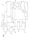
- the illustration of the bridging function as a state machine according to FIG. 2 shows how, starting from a start and finish, or end point of the execution of the automatic bridging function routine, a first pinching inquiry 13 is run through. If this state of the surface to be traversed is detected, the position of the stiffness region 4.1 is stored, the time limiter is set and the electric drive is reversed. This is done by the Einklemmparameter Items 14, from which is branched out in the monitoring module 12 also contained in the state machine 10. There, a first Klemmkrafterhöhung 16 is brought about, which is then transmitted by the control of the electric drive within the first start-up routine 15 on the surface.
- the monitoring module 12 monitors whether, for example, a previously set engine standstill time of, for example, 10 seconds is exceeded or not. If so, a branch is also made to the start or destination query point 11 and the automatic bridging function is reset. A reset of the automatic lock-up function also takes place when a reversal of the direction of rotation of the electric drive has occurred in the query 25 of the control of the electric drive. If a reversal of direction of rotation occurs, the approaching surface - be it a window pane or a sunroof - returns to its open position. Even in the closed position of each area to be traversed, the automatic override function 10 is reset.
- a sequence of the automatic bridging function according to the diagram according to FIG. 2 is approximately as follows:
- the electric drive reverses;
- an increase of the release force which is for example as F> 100 N.
- a second start-up routine 19 a second start-up with a stepped increase in the release force to overcome the obstacle, the binding area 4.1 to overcome.
- the release force is stored and assigned to the path area 4.1 at which the stiffness area 4.1 was located.
- a set to be overcome trajectory force threshold for the release force can be adjusted so that the driving surface to be traversed driving electric drive speed and tripping force adapted to the Schwerdorfkeits Scheme 4.1 and traverses the path sections 2 with predetermined release force 5 and upon detection of the previously stored stiffness range 4.1 of the electric drive is operated with a stepped increased release force.
Landscapes
- Engineering & Computer Science (AREA)
- Mechanical Engineering (AREA)
- Power-Operated Mechanisms For Wings (AREA)
- Window Of Vehicle (AREA)
Claims (10)
- Procédé de dépassement de duretés partielles de fonctionnement de surfaces mobiles logées dans des guides et déplaçables au moyen de moteurs électriques d'entraînement, dont la commande prévoit une fonction de dépassement,
caractérisé en ce qu'
on crée une fonction de surveillance automatique au moyen d'une commande automatique (10), et on fait varier la force de dégagement en une ou plusieurs étapes à l'intérieur d'une zone de dureté de fonctionnement (4.1). - Procédé selon la revendication 1,
caractérisé en ce que
la commande automatique (10) augmente la force de dégagement à l'endroit de la zone de dureté de fonctionnement. - Procédé selon la revendication 1,
caractérisé en ce que
la commande automatique (10) modifie la vitesse de rotation de l'entraînement électrique des surfaces à déplacer. - Procédé selon la revendication 1,
caractérisé en ce que
la commande automatique (10) contient une première routine de démarrage (15) ainsi qu'une deuxième routine de démarrage (19) pour augmenter graduellement la force de dégagement (16, 18). - Procédé selon la revendication 1,
caractérisé en ce que
la commande automatique (10) limite la force de fermeture (24, 25). - Procédé selon la revendication 1,
caractérisé en ce que
le composant de surveillance (12) revient au point de départ et de destination (11) après un temps prédéterminé ou après une inversion du sens de rotation de l'entraînement électrique. - Procédé selon la revendication 4,
caractérisé en ce que
lors d'une exécution successive de la première routine de démarrage (15) et de la deuxième routine de démarrage (19), à chaque exécution, on augmente la force de dégagement jusqu'à atteindre la force de dégagement maximale fixée, et on mémorise cette valeur dépassant la zone de fonctionnement (4.1) dans une mémoire adaptative. - Procédé selon la revendication 1,
caractérisé en ce qu'
on remet à zéro la fonction automatique de dépassement, lorsque la surface à déplacer atteint sa position de fermeture respective. - Procédé selon la revendication 1,
caractérisé en ce qu'
on remet à zéro la fonction automatique de dépassement, si le temps d'arrêt de l'entraînement électrique dépasse un temps prédéterminé. - Procédé selon la revendication 1,
caractérisé en ce qu'
on remet à zéro la commande automatique de dépassement, lorsqu'on commande l'inversion du sens de rotation de l'entraînement électrique.
Applications Claiming Priority (2)
| Application Number | Priority Date | Filing Date | Title |
|---|---|---|---|
| DE10008040 | 2000-02-22 | ||
| DE10008040A DE10008040A1 (de) | 2000-02-22 | 2000-02-22 | Verfahren zur Überbrückung partieller Schwergängigkeit an verfahrbaren Flächen |
Publications (2)
| Publication Number | Publication Date |
|---|---|
| EP1127724A1 EP1127724A1 (fr) | 2001-08-29 |
| EP1127724B1 true EP1127724B1 (fr) | 2006-05-03 |
Family
ID=7631832
Family Applications (1)
| Application Number | Title | Priority Date | Filing Date |
|---|---|---|---|
| EP01102206A Expired - Lifetime EP1127724B1 (fr) | 2000-02-22 | 2001-01-31 | Méthode pour surmonter une dureté partielle de panneaux mobiles |
Country Status (4)
| Country | Link |
|---|---|
| US (2) | US6498450B2 (fr) |
| EP (1) | EP1127724B1 (fr) |
| DE (2) | DE10008040A1 (fr) |
| ES (1) | ES2261281T3 (fr) |
Families Citing this family (3)
| Publication number | Priority date | Publication date | Assignee | Title |
|---|---|---|---|---|
| US6873127B2 (en) * | 2002-05-10 | 2005-03-29 | Wayne-Dalton Corp. | Method and device for adjusting an internal obstruction force setting for a motorized garage door operator |
| DE102008054249A1 (de) * | 2008-10-24 | 2010-04-29 | Dr.Ing.H.C.F.Porsche Aktiengesellschaft | Verfahren zum Schließen einer einklemmüberwachten Fahrzeugöffnung |
| DE102012003481A1 (de) * | 2012-02-21 | 2013-08-22 | Audi Ag | Verfahren zum Betätigen einer Klappe eines Kraftfahrzeugs |
Family Cites Families (6)
| Publication number | Priority date | Publication date | Assignee | Title |
|---|---|---|---|---|
| US5051672A (en) * | 1989-04-28 | 1991-09-24 | Kabushiki Kaisha Riken | Automatic window/door system |
| DE4031257A1 (de) * | 1990-10-04 | 1992-04-09 | Bosch Gmbh Robert | Vorrichtung zum betreiben von elektromotorisch angetriebenen teilen |
| US6064165A (en) * | 1992-04-22 | 2000-05-16 | Nartron Corporation | Power window or panel controller |
| NL1000371C2 (nl) * | 1995-05-16 | 1996-11-19 | Nedap Nv | Schuifdakbesturing met incrementele positiebepaling met dynamische nulstelling. |
| EP0900679B1 (fr) * | 1997-09-04 | 2003-10-22 | Robert Bosch Gmbh | Système d'entrainement à moteur électrique |
| JP2000274142A (ja) * | 1999-03-23 | 2000-10-03 | Koito Mfg Co Ltd | パワーウインドの安全装置 |
-
2000
- 2000-02-22 DE DE10008040A patent/DE10008040A1/de not_active Withdrawn
-
2001
- 2001-01-31 EP EP01102206A patent/EP1127724B1/fr not_active Expired - Lifetime
- 2001-01-31 ES ES01102206T patent/ES2261281T3/es not_active Expired - Lifetime
- 2001-01-31 DE DE50109657T patent/DE50109657D1/de not_active Expired - Lifetime
- 2001-02-20 US US09/788,951 patent/US6498450B2/en not_active Expired - Lifetime
- 2001-04-06 US US09/827,989 patent/US20020021099A1/en not_active Abandoned
Also Published As
| Publication number | Publication date |
|---|---|
| US20020021099A1 (en) | 2002-02-21 |
| DE50109657D1 (de) | 2006-06-08 |
| DE10008040A1 (de) | 2001-09-13 |
| ES2261281T3 (es) | 2006-11-16 |
| EP1127724A1 (fr) | 2001-08-29 |
| US6498450B2 (en) | 2002-12-24 |
| US20010022504A1 (en) | 2001-09-20 |
Similar Documents
| Publication | Publication Date | Title |
|---|---|---|
| EP0865137B1 (fr) | Procédé pour controller la procédure de fermeture de dispositifs de fermeture avec au moins un membre actionné par moteur électrique | |
| EP1332538B1 (fr) | Procede pour commander un processus de reglage d'une partie | |
| EP2993751B1 (fr) | Procede et dispositif de commande d'un dispositif de deplacement d'un vehicule automobile | |
| DE19840163A1 (de) | Antriebsvorrichtung und Verfahren zum Verstellen eines Fahrzeugteils | |
| EP2117888A1 (fr) | Dispositif et procédé de commande d'une unité d'entraînement d'un système essuie-glace | |
| DE102008039146A1 (de) | Steuergerät für eine Verschließtafel | |
| DE19941475A1 (de) | Verfahren zum Begrenzen der Schließkraft von beweglichen Teilen | |
| DE102006053080A1 (de) | Wandelement-Steuersystem | |
| DE3335407C2 (fr) | ||
| EP1216868B1 (fr) | Toit ouvrant pour vehicule avec dispositif anti-pincement et procédé correspondant | |
| EP0479045A2 (fr) | Dispositif d'actionnement d'éléments entraînés par moteur électrique | |
| DE19840162A1 (de) | Antriebsvorrichtung und Verfahren zum Verstellen eines Fahrzeugteils | |
| DE10008040A1 (de) | Verfahren zur Überbrückung partieller Schwergängigkeit an verfahrbaren Flächen | |
| DE112018001091T5 (de) | Antriebsvorrichtung für einen Öffnungs- und Schließkörper | |
| DE19615581A1 (de) | Verfahren zum Ansteuern elektrischer Antriebe in Fahrzeugen | |
| EP1438778B1 (fr) | Procede de controle d'un processus reversible de groupes commandes electriquement | |
| DE102006033022A1 (de) | Verfahren und Vorrichtung zum Schutz gegen Einklemmen bei einem motorbetriebenen Schließsystem | |
| DE4330112C2 (de) | Schaltanordnung zur Steuerung der Geschwindigkeit eines Scheibenwischers in Kraftfahrzeugen | |
| EP1148606B1 (fr) | Procédé pour détecter de l'information perdu dans un microprocesseur | |
| DE102013206914A1 (de) | Verfahren zur Steuerung eines elektromotorischen Stellantriebs einer Stellvorrichtung eines Fahrzeugs | |
| DE29514786U1 (de) | Stellantrieb | |
| DE102020203886A1 (de) | Verfahren zum Betrieb einer elektromotorischen Verstellvorrichtung eines Kraftfahrzeugs | |
| DE10119103B4 (de) | Elektrisch betriebenes Schiebedach für ein Kraftfahrzeug | |
| DE2161789C3 (de) | Einrichtung für den intermittierenden Betrieb eines Scheibenwischers | |
| DE102007040711B4 (de) | Steuervorrichtung zur Ansteuerung von Aktuatoren |
Legal Events
| Date | Code | Title | Description |
|---|---|---|---|
| PUAI | Public reference made under article 153(3) epc to a published international application that has entered the european phase |
Free format text: ORIGINAL CODE: 0009012 |
|
| AK | Designated contracting states |
Kind code of ref document: A1 Designated state(s): DE ES FR GB IT SE Kind code of ref document: A1 Designated state(s): AT BE CH CY DE DK ES FI FR GB GR IE IT LI LU MC NL PT SE TR |
|
| AX | Request for extension of the european patent |
Free format text: AL;LT;LV;MK;RO;SI |
|
| 17P | Request for examination filed |
Effective date: 20020228 |
|
| AKX | Designation fees paid |
Free format text: DE ES FR GB IT SE |
|
| GRAP | Despatch of communication of intention to grant a patent |
Free format text: ORIGINAL CODE: EPIDOSNIGR1 |
|
| GRAS | Grant fee paid |
Free format text: ORIGINAL CODE: EPIDOSNIGR3 |
|
| GRAA | (expected) grant |
Free format text: ORIGINAL CODE: 0009210 |
|
| AK | Designated contracting states |
Kind code of ref document: B1 Designated state(s): DE ES FR GB IT SE |
|
| PG25 | Lapsed in a contracting state [announced via postgrant information from national office to epo] |
Ref country code: IT Free format text: LAPSE BECAUSE OF FAILURE TO SUBMIT A TRANSLATION OF THE DESCRIPTION OR TO PAY THE FEE WITHIN THE PRESCRIBED TIME-LIMIT;WARNING: LAPSES OF ITALIAN PATENTS WITH EFFECTIVE DATE BEFORE 2007 MAY HAVE OCCURRED AT ANY TIME BEFORE 2007. THE CORRECT EFFECTIVE DATE MAY BE DIFFERENT FROM THE ONE RECORDED. Effective date: 20060503 |
|
| REG | Reference to a national code |
Ref country code: GB Ref legal event code: FG4D Free format text: NOT ENGLISH |
|
| REF | Corresponds to: |
Ref document number: 50109657 Country of ref document: DE Date of ref document: 20060608 Kind code of ref document: P |
|
| PG25 | Lapsed in a contracting state [announced via postgrant information from national office to epo] |
Ref country code: SE Free format text: LAPSE BECAUSE OF FAILURE TO SUBMIT A TRANSLATION OF THE DESCRIPTION OR TO PAY THE FEE WITHIN THE PRESCRIBED TIME-LIMIT Effective date: 20060803 |
|
| GBT | Gb: translation of ep patent filed (gb section 77(6)(a)/1977) |
Effective date: 20060824 |
|
| ET | Fr: translation filed | ||
| REG | Reference to a national code |
Ref country code: ES Ref legal event code: FG2A Ref document number: 2261281 Country of ref document: ES Kind code of ref document: T3 |
|
| PLBE | No opposition filed within time limit |
Free format text: ORIGINAL CODE: 0009261 |
|
| STAA | Information on the status of an ep patent application or granted ep patent |
Free format text: STATUS: NO OPPOSITION FILED WITHIN TIME LIMIT |
|
| 26N | No opposition filed |
Effective date: 20070206 |
|
| REG | Reference to a national code |
Ref country code: FR Ref legal event code: PLFP Year of fee payment: 16 |
|
| REG | Reference to a national code |
Ref country code: FR Ref legal event code: PLFP Year of fee payment: 17 |
|
| REG | Reference to a national code |
Ref country code: FR Ref legal event code: PLFP Year of fee payment: 18 |
|
| PGFP | Annual fee paid to national office [announced via postgrant information from national office to epo] |
Ref country code: ES Payment date: 20200219 Year of fee payment: 20 Ref country code: GB Payment date: 20200127 Year of fee payment: 20 Ref country code: DE Payment date: 20200324 Year of fee payment: 20 Ref country code: IT Payment date: 20200122 Year of fee payment: 20 |
|
| PGFP | Annual fee paid to national office [announced via postgrant information from national office to epo] |
Ref country code: FR Payment date: 20200123 Year of fee payment: 20 |
|
| REG | Reference to a national code |
Ref country code: DE Ref legal event code: R071 Ref document number: 50109657 Country of ref document: DE |
|
| REG | Reference to a national code |
Ref country code: GB Ref legal event code: PE20 Expiry date: 20210130 |
|
| PG25 | Lapsed in a contracting state [announced via postgrant information from national office to epo] |
Ref country code: GB Free format text: LAPSE BECAUSE OF EXPIRATION OF PROTECTION Effective date: 20210130 |
|
| REG | Reference to a national code |
Ref country code: ES Ref legal event code: FD2A Effective date: 20210604 |
|
| PG25 | Lapsed in a contracting state [announced via postgrant information from national office to epo] |
Ref country code: ES Free format text: LAPSE BECAUSE OF EXPIRATION OF PROTECTION Effective date: 20210201 |