EP2993751B1 - Procede et dispositif de commande d'un dispositif de deplacement d'un vehicule automobile - Google Patents
Procede et dispositif de commande d'un dispositif de deplacement d'un vehicule automobile Download PDFInfo
- Publication number
- EP2993751B1 EP2993751B1 EP15180934.0A EP15180934A EP2993751B1 EP 2993751 B1 EP2993751 B1 EP 2993751B1 EP 15180934 A EP15180934 A EP 15180934A EP 2993751 B1 EP2993751 B1 EP 2993751B1
- Authority
- EP
- European Patent Office
- Prior art keywords
- force
- speed
- adjustment
- drive
- setpoint value
- Prior art date
- Legal status (The legal status is an assumption and is not a legal conclusion. Google has not performed a legal analysis and makes no representation as to the accuracy of the status listed.)
- Not-in-force
Links
Images

Classifications
-
- F—MECHANICAL ENGINEERING; LIGHTING; HEATING; WEAPONS; BLASTING
- F02—COMBUSTION ENGINES; HOT-GAS OR COMBUSTION-PRODUCT ENGINE PLANTS
- F02D—CONTROLLING COMBUSTION ENGINES
- F02D45/00—Electrical control not provided for in groups F02D41/00 - F02D43/00
-
- H—ELECTRICITY
- H02—GENERATION; CONVERSION OR DISTRIBUTION OF ELECTRIC POWER
- H02H—EMERGENCY PROTECTIVE CIRCUIT ARRANGEMENTS
- H02H7/00—Emergency protective circuit arrangements specially adapted for specific types of electric machines or apparatus or for sectionalised protection of cable or line systems, and effecting automatic switching in the event of an undesired change from normal working conditions
- H02H7/08—Emergency protective circuit arrangements specially adapted for specific types of electric machines or apparatus or for sectionalised protection of cable or line systems, and effecting automatic switching in the event of an undesired change from normal working conditions for dynamo-electric motors
- H02H7/085—Emergency protective circuit arrangements specially adapted for specific types of electric machines or apparatus or for sectionalised protection of cable or line systems, and effecting automatic switching in the event of an undesired change from normal working conditions for dynamo-electric motors against excessive load
- H02H7/0851—Emergency protective circuit arrangements specially adapted for specific types of electric machines or apparatus or for sectionalised protection of cable or line systems, and effecting automatic switching in the event of an undesired change from normal working conditions for dynamo-electric motors against excessive load for motors actuating a movable member between two end positions, e.g. detecting an end position or obstruction by overload signal
-
- B—PERFORMING OPERATIONS; TRANSPORTING
- B60—VEHICLES IN GENERAL
- B60J—WINDOWS, WINDSCREENS, NON-FIXED ROOFS, DOORS, OR SIMILAR DEVICES FOR VEHICLES; REMOVABLE EXTERNAL PROTECTIVE COVERINGS SPECIALLY ADAPTED FOR VEHICLES
- B60J7/00—Non-fixed roofs; Roofs with movable panels, e.g. rotary sunroofs
- B60J7/02—Non-fixed roofs; Roofs with movable panels, e.g. rotary sunroofs of sliding type, e.g. comprising guide shoes
- B60J7/04—Non-fixed roofs; Roofs with movable panels, e.g. rotary sunroofs of sliding type, e.g. comprising guide shoes with rigid plate-like element or elements, e.g. open roofs with harmonica-type folding rigid panels
- B60J7/057—Driving or actuating arrangements e.g. manually operated levers or knobs
- B60J7/0573—Driving or actuating arrangements e.g. manually operated levers or knobs power driven arrangements, e.g. electrical
-
- B—PERFORMING OPERATIONS; TRANSPORTING
- B62—LAND VEHICLES FOR TRAVELLING OTHERWISE THAN ON RAILS
- B62D—MOTOR VEHICLES; TRAILERS
- B62D5/00—Power-assisted or power-driven steering
- B62D5/04—Power-assisted or power-driven steering electrical, e.g. using an electric servo-motor connected to, or forming part of, the steering gear
- B62D5/0457—Power-assisted or power-driven steering electrical, e.g. using an electric servo-motor connected to, or forming part of, the steering gear characterised by control features of the drive means as such
- B62D5/0481—Power-assisted or power-driven steering electrical, e.g. using an electric servo-motor connected to, or forming part of, the steering gear characterised by control features of the drive means as such monitoring the steering system, e.g. failures
- B62D5/0487—Power-assisted or power-driven steering electrical, e.g. using an electric servo-motor connected to, or forming part of, the steering gear characterised by control features of the drive means as such monitoring the steering system, e.g. failures detecting motor faults
Definitions
- the invention relates to a method for controlling an adjusting device of a motor vehicle and an adjusting device operating thereafter.
- an operating range is selected for an electric motor which drives an assembly such as a windshield wiper or a window pane of a power window.
- Working range here is understood to mean a torque and speed band within which the electric motor is operated and whose respective combinations are permissible during operation.
- the torque of the electric motor is monitored during operation. As soon as a torque occurs that is above or at the limit of the torque band, the electric motor is regulated to the maximum torque of the torque band.
- a method of controlling and controlling the movement of electrically powered units is known.
- the normal curve is the force required for the adjustment as a function of the adjustment.
- an excess force is defined with which an envelope is calculated in particular by adding to the normal curve.
- the adjusting force is limited to this. If no further adjustment of the window pane takes place within a predetermined period of time, the movement of the window pane is stopped or the window pane is reversed.
- the envelope and / or the normal curve are preferably determined individually on a test stand for the electric motor and in a table or a characteristic field in dependence stored by, for example, the engine speed, the operating and / or ambient temperature.
- the invention has for its object to provide an improved method for controlling an adjustment of a motor vehicle, in which a secure adjustment of the adjustment is guaranteed. In particular, any trapping forces are to be reduced. Furthermore, a suitable adjustment of a motor vehicle to be specified with a motor-driven adjustment.
- the adjustment of the motor vehicle is for example an electrically operated vehicle door, a tailgate, an electric window, an electric sunroof or a darkening device.
- the proposed method is preferably used during a closing movement of the adjustment.
- the speed of the drive is spent by means of which the adjustment part along an adjustment path is controlled to a speed setpoint, this control is carried out at least in a portion of the adjustment.
- the speed setpoint value is, for example, constant at least in sections along the adjustment path or is functionally related to the already traveled adjustment path and / or the position of the adjustment part.
- the speed setpoint when the window pane retracts into a top disc stop, which is usually provided with a sealing rubber is reduced in comparison with the other speed setpoint.
- the speed setpoint is stored, for example, in a table or in a map, in which case in particular the speed setpoint is stored as a function of the operating and / or the ambient temperature and other environment variables.
- the drive force is regulated to a force setpoint value.
- the force setpoint is less than a legal limit or a value that would damage the adjuster or any occupant of the vehicle.
- the force setpoint is constant at least in sections along the adjustment path.
- the force set point can also be dependent on environment variables.
- This control is active for a first period of time, wherein the time period is variable, for example, by a user.
- this time span can be shortened or extended by actuating a switch which controls the adjusting device, for example a push button of the electric window lifter.
- the first time period is adapted to current requirements or operating conditions of the adjustment device.
- the first time period is constant and is for example between 0.1 s and 1 s, preferably 0.5 s.
- the drive operatively connected to the adjusting part is stopped or the adjusting part is reversed.
- the drive is thus controlled in such a way that the adjusting part is moved along the adjustment path in the direction opposite to the original direction of movement.
- Pinching is understood to mean that the binding is caused by an object that is within the adjustment range of the adjustment member and in mechanical contact therewith.
- the object for example a body part of a person, such as a hand, is to be protected from injury or damage. Additionally or alternatively, the adjustment should be protected from damage, if the object is designed such that a further movement of the adjustment along the adjustment path in the original direction of movement would lead to damage to the adjustment. In particular, the object counteracts the original direction of movement of the adjustment.
- the binding is due to a short-term disturbance of the adjustment, such as in particular a vibration or contamination within any guide rails, within which the adjustment is located, so the adjustment is again after the first period of time on the speed Setpoint controlled.
- the binding is detected in normal operation on the basis of the force required for the adjustment of the adjustment, which takes place at a speed corresponding to the speed setpoint required force.
- the force command value is controlled as soon as the value for the drive force exceeds a specific limit value and / or the increase in the required drive force within a defined period of time exceeds a specific increase limit value.
- the trapping case is characterized in that despite the driving force applied by the drive in the amount of a suitable force setpoint, the speed of the adjustment is zero. However, if the value of the speed is above a certain limit value or if the speed increases by a certain value within a certain period of time, the speed setpoint value is regulated again after the first time span has elapsed. In this case, the first time period is terminated, for example, as soon as the value of the speed reaches the specified limit value.
- the first period of time is suitably lengthened, ie the regulation continues to the force setpoint value until a distinction is possible. This is the case, for example, if the adjustment part moves along the adjustment path, but the value of the speed is below the specified limit value.
- the speed of the adjustment part is adjusted continuously, in particular linearly, to the desired speed value.
- the noise level of the occupants of the motor vehicle is lower.
- the appearance of the occupants during operation of the adjustment is more appealing because the adjustment performs no jerky movements.
- a value for the driving force realized during normal operation is used as the force set value in order to achieve a reduction of the possible pinching forces in the event of trapping.
- the object is thus not excessively damaged or injured during the phase of the control to the force setpoint, since the force setpoint has already occurred before the occurrence of this control phase and was also expected during this rule with damage or injury to the object.
- a force value existing before the changeover from the speed or speed control to the force control is used as a setpoint, without the speed or engine speed being necessarily reduced beforehand.
- the force command value is continuously updated in normal operation and corresponds to the value of the driving force realized before a third time period, which is for example between 0 s and 1 s and in particular 0.01 s.
- the force setpoint is adapted to current requirements of the adjustment, for example, a changed ambient temperature.
- the force setpoint is suitably kept constant for a fourth time span.
- the force command value is not updated within the fourth time period when the fourth time period is longer than the third time period.
- the force setpoint corresponds to the force setpoint that was controlled during the first time period.
- the force setpoint for the duration of the fourth period of time the force setpoint was regulated to, while the adjustment was spent by the binding.
- the fourth time interval is expediently between 0.05 s and 2 s and in particular 0.5 s. It is suitably constant or terminated as soon as the speed of the adjustment exceeds a limit speed. Thus, for example, it is prevented that the force command value is continuously increased in the case of a number of bindings. Thus, often during the first time period subsequent speed control, an increased driving force is required to accelerate the drive again to the speed setpoint.
- the adjusting device has a speed and force control, wherein the control is realized for example in two separate control units or in an integrated control unit.
- the control is at least active when the adjustment is located in a portion of the adjustment and the adjustment is to be moved.
- the speed of the drive is controlled by the speed control to a speed setpoint.
- the force control intervenes and regulates the drive force to a force setpoint for a first period of time. After expiry of the first period of time, the adjusting part is reversed by means of a suitable control of the drive or the drive is at least stopped when the sluggishness is due to a trapping case. Otherwise, after the expiry of the first time period, the speed of the drive is re-regulated to the speed setpoint.
- the drive is a conventional electric motor and the adjustment means an electric window.
- the rotational speed of the electric motor is detected by means of Hall sensors and thus the speed of the drive or of the adjusting part is measured.
- the electric motor is powered by means of a known pulse width modulation with energy.
- the driving force is determined by means of a motor-specific characteristic and the measured speed.
- the speed and force control is designed such that it can be integrated into existing components of a conventional power window, so that the window can be converted to the proposed method, for example by means of a software update.
- the embodiments of the above method are mutatis mutandis transferable to the adjustment.
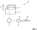
- Fig. 1 schematically an adjusting device 2 with an adjustment part 4 is shown.
- the adjusting device 2 is, for example, an electric window, which is integrated in a door 6 of a motor vehicle.
- the adjusting part 4 is in this case a window pane, which is moved by means of a drive 8 along an adjustment path 10.
- the drive 8 is controlled by means of a control unit 12, which is activated by a button 14 by an occupant of the motor vehicle.
- a speed and force control 16 Within the control unit 12 is a speed and force control 16.
- the drive 8 is for example an electric motor which is operated by means of pulse width modulation. By means of variation of the pulse / pause ratio, the electric power supplied to the drive 8 is controlled. In particular, this energy is functionally related to the driving force 18, which spans the adjusting part 4 along the adjustment path 10. The relationship is linear, for example, and during the control, the applied to the electric motor electrical voltage in particular constant. Furthermore, the electric motor preferably has two Hall sensors, by means of which the speed of the electric motor and thus the speed 20 of the drive 8 is measured.
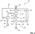
- Fig. 2 shows the timing of a method for operating the adjusting device 2, in particular during a closing operation of the window pane.
- the method is integrated in the speed and force control 16.
- a speed control 26 comes into force, which regulates the speed 20 of the drive 8 to a speed set value 28.
- the starting event 22 is, for example, the actuation of the pushbutton 14 or the reaching of a specific position along the adjustment path 10 by the adjusting part 4.
- the drive force 18 required for the adjustment before a third time period 30 is stored as a force set point 32. Further, the driving force 18 is monitored by means of a monitoring unit 34, whether a binding 36 is present. If, for example, the drive force 18 rises very sharply or is higher than a certain limit value, the monitoring unit 34 outputs a positive signal 38. Otherwise, the monitoring unit 34 outputs a negative signal 40. The negative signal 40 is monitored in a further monitoring unit 34. whether the adjustment part 4 has reached the end of the adjustment path 10 or at least the end of the region of the adjustment path 10 within which the adjustment part 4 is moved by means of the method. If so, an end event 42 terminates the process. Otherwise, by means of the speed control 26, the speed 20 of the adjusting part 4 is regulated to the speed setpoint 28.
- the drive force 18 is regulated to the desired force value 32 for a first time interval 46 by means of a force control 44. After expiration of the first period of time 46, a check is made by means of a further monitoring unit 34 as to whether the binding 36 is a trapping case 48. The distinction is made on the basis of the realized speed 20 of the drive 8. For example, if the speed 20 is zero or near zero, the pinch case 48 is identified. Should an object, such as a hand of one of the occupants of the motor vehicle, be acted upon by the window, then an entrapment event 50 occurs.
- the drive 8 is either stopped or controlled such that the adjusting part 4 moves in the direction opposite to the original direction of movement, so that the object is released from the entrapment. Otherwise, if there is no entrapment 48, the speed 20 of the drive 8 is linearly adjusted again to the speed setpoint 28 by means of a speed adjustment unit 52. The speed control 26 then becomes active again.
- Fig. 3 is extracts of the time course of the driving force 18 and the speed 20 of the drive 8 shown.
- the speed 20 is regulated to the speed setpoint 28. If the driving force 18 required for this exceeds a limit, the case of stiffness 36 is identified.
- the driving force 18 for the first period 46 is regulated to the force command value 32.
- the value of the driving force 18, which served as the driving force 18 for the third time period 30 before the beginning of the binding 36 is used as the desired force value 32.
- the driving force 18 is first reduced to a first force 54, wherein the first force 54 is almost zero.
- the drive force 18 is increased linearly to the desired force value 32.
- the speed 20 of the drive 8 is monitored. If this value is zero or almost zero after expiration of the first period of time 46, it is assumed that an object is located within the adjustment path 10 and thus the trapping case 48 is present. To end the entrapment of the drive 8 is then reversed. The adjusting part 4 now moves in the direction opposite to the original direction of movement. After a certain period of time has elapsed, for example, the drive 8 is completely stopped.
- Fig. 4 is - unlike the one in Fig. 3
- the speed 20 is no longer zero, for example, as shown here, it is approximately one-third of the speed set point 28.
- the controller again adapts to the speed setpoint 28, wherein the speed 20 is increased linearly to the speed setpoint 28. Occurs within a fourth time period 58 after the first time period 46, a further binding 36, then the previous force setpoint 32 is used in the renewed force control. Only after expiration of the fourth time period 58 is the desired force value 32 again updated and corresponds to the respective required before the third period 30 for the adjustment driving force 18. If there is no further binding 36 before, the adjustment is 2 again in normal operation 24th
Landscapes
- Engineering & Computer Science (AREA)
- Chemical & Material Sciences (AREA)
- Combustion & Propulsion (AREA)
- Mechanical Engineering (AREA)
- General Engineering & Computer Science (AREA)
- Power-Operated Mechanisms For Wings (AREA)
- Window Of Vehicle (AREA)
Claims (6)
- Procédé de commande d'un dispositif de positionnement (2) d'un véhicule automobile, notamment d'un lève-vitre, comprenant une partie de positionnement (4) à entraînement motorisé, avec lequel la vitesse (20) du mécanisme d'entraînement (8) est régulée à une valeur de consigne de vitesse (28) au moins dans une zone partielle d'une course de positionnement (10) en fonctionnement normal (24) et, dans le cas d'une difficulté de mouvement (36), la force d'entraînement (18) est régulée à une valeur de consigne de force (32) pendant un premier intervalle de temps (46), après l'écoulement du premier intervalle de temps (46),- soit le sens de la partie de positionnement (4) étant inversé ou le mécanisme d'entraînement (8) étant au moins arrêté lorsqu'un cas de coincement (48) est reconnu,- soit la vitesse (20) du mécanisme d'entraînement (8) étant de nouveau régulée à la valeur de consigne de vitesse (28) lorsque le cas de difficulté de mouvement (36) n'est pas un cas de coincement (48),caractérisé en ce
que la valeur de consigne de force (32) utilisée est une valeur pour la force d'entraînement (18) qui est réalisée pendant le fonctionnement normal (24), la valeur de consigne de force (32) étant continuellement actualisé en fonctionnement normal (24), et la valeur de consigne de force (32) correspondant à la valeur de la force d'entraînement (18) réalisée avant un troisième intervalle de temps (30). - Procédé selon la revendication 1,
caractérisé en ce- que la difficulté de mouvement (36) est reconnue à l'aide du changement de force en fonctionnement normal (24) et- que le cas de coincement (48) est reconnu à l'aide du changement de vitesse dans le cas de la difficulté de mouvement (36). - Procédé selon la revendication 1 ou 2, caractérisé en ce qu'après l'écoulement du premier intervalle de temps (46), l'adaptation de la vitesse (20) à la valeur de consigne de vitesse (28) s'effectue de façon linéaire.
- Procédé selon l'une des revendications 1 à 3, caractérisé en ce qu'après l'écoulement du premier intervalle de temps (46), lors de la régulation rétablie à la valeur de consigne de vitesse (28), la valeur de consigne de force (32) est maintenue constante au sein d'un quatrième intervalle de temps (58) et correspond à la valeur de consigne de force (32) utilisée pour la régulation de force précédente.
- Dispositif de positionnement (2) d'un véhicule automobile, notamment d'un lève-vitre, comprenant une partie de positionnement (4) à entraînement motorisé, et comprenant une régulation de vitesse et de force (16) qui régule la vitesse (20) du mécanisme d'entraînement (8) à une valeur de consigne de vitesse (28) au moins dans une zone partielle d'une course de positionnement (10) en fonctionnement normal (24) et, dans le cas d'une difficulté de mouvement (36), régule la force d'entraînement (18) à une valeur de consigne de force (32), après l'écoulement d'un premier intervalle de temps (46), dans un cas de coincement, soit le sens de la partie de positionnement (4) étant inversé ou le mécanisme d'entraînement (8) s'arrêtant, soit, le cas contraire, une régulation de vitesse du mécanisme d'entraînement (8) étant rétablie à la valeur de consigne de vitesse (28), la valeur de consigne de force (32) étant une valeur réalisée pour la force d'entraînement (18) durant le fonctionnement normal (24), laquelle correspond à la valeur de la force d'entraînement (18) réalisée avant un troisième intervalle de temps (30).
- Utilisation d'un dispositif de positionnement (2) d'un véhicule automobile pour mettre en oeuvre un procédé selon l'une des revendications 1 à 4.
Applications Claiming Priority (3)
| Application Number | Priority Date | Filing Date | Title |
|---|---|---|---|
| DE102010055650A DE102010055650A1 (de) | 2010-12-22 | 2010-12-22 | Verfahren und Einrichtung zum Steuern einer Verstelleinrichtung eines Kraftfahrzeugs |
| EP11796617.6A EP2656466B1 (fr) | 2010-12-22 | 2011-11-21 | Procédé et dispositif pour commander un dispositif de réglage d'un véhicule automobile |
| PCT/EP2011/005846 WO2012084109A1 (fr) | 2010-12-22 | 2011-11-21 | Procédé et dispositif pour commander un dispositif de réglage d'un véhicule automobile |
Related Parent Applications (2)
| Application Number | Title | Priority Date | Filing Date |
|---|---|---|---|
| EP11796617.6A Division-Into EP2656466B1 (fr) | 2010-12-22 | 2011-11-21 | Procédé et dispositif pour commander un dispositif de réglage d'un véhicule automobile |
| EP11796617.6A Division EP2656466B1 (fr) | 2010-12-22 | 2011-11-21 | Procédé et dispositif pour commander un dispositif de réglage d'un véhicule automobile |
Publications (2)
| Publication Number | Publication Date |
|---|---|
| EP2993751A1 EP2993751A1 (fr) | 2016-03-09 |
| EP2993751B1 true EP2993751B1 (fr) | 2019-06-12 |
Family
ID=45349143
Family Applications (2)
| Application Number | Title | Priority Date | Filing Date |
|---|---|---|---|
| EP15180934.0A Not-in-force EP2993751B1 (fr) | 2010-12-22 | 2011-11-21 | Procede et dispositif de commande d'un dispositif de deplacement d'un vehicule automobile |
| EP11796617.6A Not-in-force EP2656466B1 (fr) | 2010-12-22 | 2011-11-21 | Procédé et dispositif pour commander un dispositif de réglage d'un véhicule automobile |
Family Applications After (1)
| Application Number | Title | Priority Date | Filing Date |
|---|---|---|---|
| EP11796617.6A Not-in-force EP2656466B1 (fr) | 2010-12-22 | 2011-11-21 | Procédé et dispositif pour commander un dispositif de réglage d'un véhicule automobile |
Country Status (5)
| Country | Link |
|---|---|
| US (1) | US9388762B2 (fr) |
| EP (2) | EP2993751B1 (fr) |
| CN (1) | CN103270661B (fr) |
| DE (1) | DE102010055650A1 (fr) |
| WO (1) | WO2012084109A1 (fr) |
Families Citing this family (12)
| Publication number | Priority date | Publication date | Assignee | Title |
|---|---|---|---|---|
| DE102010055650A1 (de) * | 2010-12-22 | 2012-06-28 | Brose Fahrzeugteile Gmbh & Co. Kommanditgesellschaft, Hallstadt | Verfahren und Einrichtung zum Steuern einer Verstelleinrichtung eines Kraftfahrzeugs |
| DE102016101487B4 (de) * | 2015-01-30 | 2023-11-09 | Denso Corporation | Fahrzeug-Fensteröffnungsvorrichtung |
| US10208520B2 (en) | 2016-05-16 | 2019-02-19 | Schlage Lock Company Llc | Method and apparatus for adjusting the closing force of a door |
| DE102016208596A1 (de) * | 2016-05-19 | 2017-11-23 | Robert Bosch Gmbh | Verfahren zum Betreiben einer Schließvorrichtung sowie eine Schließvorrichtung |
| US10030432B1 (en) | 2017-06-20 | 2018-07-24 | Ford Global Technologies, Llc | System and method for window motion control |
| DE102017215383A1 (de) * | 2017-09-01 | 2019-03-07 | Brose Fahrzeugteile Gmbh & Co. Kommanditgesellschaft, Bamberg | Verfahren zum Betrieb eines Türmoduls eines Kraftfahrzeugs |
| DE102018205342A1 (de) * | 2018-04-10 | 2019-10-10 | Brose Fahrzeugteile Gmbh & Co. Kommanditgesellschaft, Bamberg | Verfahren zum Betrieb eines Einklemmschutzes |
| CN108909419A (zh) * | 2018-07-16 | 2018-11-30 | 英纳法企业管理(上海)有限公司 | 汽车天窗防夹方法及系统 |
| DE102019114540A1 (de) * | 2019-05-29 | 2020-12-03 | Brose Schließsysteme GmbH & Co. Kommanditgesellschaft | Funktionskomponente einer Kraftfahrzeugschlossanordnung |
| JP7377059B2 (ja) * | 2019-10-21 | 2023-11-09 | 株式会社ユーシン | 車両開閉体の開閉制御装置 |
| EP4011665B1 (fr) * | 2020-12-10 | 2026-04-01 | Inalfa Roof Systems Group B.V. | Unité de commande et procédé de fonctionnement d'un ensemble toit ouvrant |
| US12384442B2 (en) * | 2021-10-01 | 2025-08-12 | Steering Solutions Ip Holding Corporation | Real-time pinch detection and prevention for stow path power column |
Family Cites Families (16)
| Publication number | Priority date | Publication date | Assignee | Title |
|---|---|---|---|---|
| US6064165A (en) * | 1992-04-22 | 2000-05-16 | Nartron Corporation | Power window or panel controller |
| US5982124A (en) * | 1995-08-30 | 1999-11-09 | Trw Inc. | Method and apparatus for adaptive control of a vehicle power window |
| DE19615581B4 (de) | 1996-04-19 | 2013-03-07 | Bayerische Motoren Werke Aktiengesellschaft | Verfahren zum Schutz von mechanischen und durch einen Elektromotor angetriebenen Komponentenin Fahrzeugen vor Beschädigung |
| DE19711979A1 (de) | 1997-03-12 | 1998-10-08 | Brose Fahrzeugteile | Verfahren zur elektrischen Steuerung und Regelung der Bewegung von elektrisch betriebenen Aggregaten |
| DE19901840A1 (de) * | 1999-01-19 | 2000-05-25 | Daimler Chrysler Ag | Elektrischer Stellantrieb für Kraftfahrzeugkomponenten und Verfahren zu dessen Steuerung |
| ES2155413B1 (es) * | 1999-10-22 | 2002-02-01 | Castellon Melchor Daumal | Mejoras en los sistemas antipinzamiento destinados al automovil. |
| DE202006002525U1 (de) * | 2006-02-17 | 2007-07-05 | Brose Fahrzeugteile Gmbh & Co. Kommanditgesellschaft, Coburg | Einklemmschutz einer motorisch angetriebenen Verstellvorrichtung für eine Verstellvorrichtung |
| US7479748B2 (en) * | 2006-10-25 | 2009-01-20 | Robert Bosch Gmbh | Systems and methods of tracking partition system performance |
| DE102008032963A1 (de) * | 2008-07-09 | 2010-01-14 | Brose Fahrzeugteile Gmbh & Co. Kommanditgesellschaft, Coburg | Bahngesteuerter Fensterheber eines Kraftfahrzeugs |
| CN201306085Y (zh) * | 2008-09-26 | 2009-09-09 | 瑞安市登峰福利汽配厂 | 一种汽车车窗控制装置 |
| DE102008053113A1 (de) | 2008-10-25 | 2010-05-06 | Brose Fahrzeugteile Gmbh & Co. Kg, Hallstadt | Antriebsanordnung zur motorischen Verstellung eines Verstellelements in einem Kraftfahrzeug |
| DE102008043483A1 (de) * | 2008-11-05 | 2010-05-06 | Robert Bosch Gmbh | Verfahren und Vorrichtung zum Aktivieren einer Überwachung durch eine Einklemmschutzfunktion bei einem elektrischen Schließsystem |
| DE202009000907U1 (de) * | 2009-01-23 | 2010-06-17 | Brose Fahrzeugteile Gmbh & Co. Kommanditgesellschaft, Hallstadt | Antriebsanordnung zur motorischen Verstellung eines Verstellelements eines Kraftfahrzeugs |
| DE102009027597A1 (de) * | 2009-07-09 | 2011-01-13 | Robert Bosch Gmbh | Verfahren zum Betreiben einer Schließvorrichtung eines Kraftfahrzeugs sowie eine Schließvorrichtung |
| DE102010055650A1 (de) * | 2010-12-22 | 2012-06-28 | Brose Fahrzeugteile Gmbh & Co. Kommanditgesellschaft, Hallstadt | Verfahren und Einrichtung zum Steuern einer Verstelleinrichtung eines Kraftfahrzeugs |
| DE102011111450A1 (de) * | 2011-08-30 | 2013-02-28 | Brose Fahrzeugteile Gmbh & Co. Kommanditgesellschaft, Hallstadt | Verfahren und Vorrichtung zur Überwachung eines einen rotierenden Antriebsmotor aufweisenden Antriebsaggregats, insbesondere eines Fensterhebers |
-
2010
- 2010-12-22 DE DE102010055650A patent/DE102010055650A1/de not_active Withdrawn
-
2011
- 2011-11-21 EP EP15180934.0A patent/EP2993751B1/fr not_active Not-in-force
- 2011-11-21 WO PCT/EP2011/005846 patent/WO2012084109A1/fr not_active Ceased
- 2011-11-21 EP EP11796617.6A patent/EP2656466B1/fr not_active Not-in-force
- 2011-11-21 CN CN201180061934.0A patent/CN103270661B/zh not_active Expired - Fee Related
-
2013
- 2013-06-24 US US13/924,747 patent/US9388762B2/en active Active
Non-Patent Citations (1)
| Title |
|---|
| None * |
Also Published As
| Publication number | Publication date |
|---|---|
| EP2656466A1 (fr) | 2013-10-30 |
| EP2656466B1 (fr) | 2016-02-03 |
| US9388762B2 (en) | 2016-07-12 |
| EP2993751A1 (fr) | 2016-03-09 |
| DE102010055650A1 (de) | 2012-06-28 |
| CN103270661A (zh) | 2013-08-28 |
| US20130276748A1 (en) | 2013-10-24 |
| WO2012084109A1 (fr) | 2012-06-28 |
| CN103270661B (zh) | 2015-08-19 |
Similar Documents
| Publication | Publication Date | Title |
|---|---|---|
| EP2656466B1 (fr) | Procédé et dispositif pour commander un dispositif de réglage d'un véhicule automobile | |
| EP0865137B1 (fr) | Procédé pour controller la procédure de fermeture de dispositifs de fermeture avec au moins un membre actionné par moteur électrique | |
| EP3325748B1 (fr) | Élément de porte muni d'un dispositif amortisseur pilotable | |
| EP0910883B1 (fr) | Procede de commande de la fermeture de dispositifs de fermeture pourvus d'au moins une partie deplacee par moteur electrique | |
| EP1332538B1 (fr) | Procede pour commander un processus de reglage d'une partie | |
| DE102009014808A1 (de) | Verfahren und Vorrichtung zum Ansteuern eines eine Ansprechverzögerung aufweisenden Steuerelements einer Antriebseinrichtung | |
| DE10028445B4 (de) | Verfahren zur Steuerung der Verstellbewegung eines mittels eines Elektromotors bewegten Teils einer Schließvorrichtung in einem Fahrzeug | |
| DE19758796B4 (de) | Verfahren zur Steuerung und Regelung der Verstellbewegung eines translatorisch verstellbaren Bauteils in Fahrzeugen | |
| DE102012008235B4 (de) | Präzise Stellpositionsermittlung bei einem motorisch bewegbaren Fahrzeugteil | |
| WO2022167043A1 (fr) | Procédé d'assistance motorisée du mouvement d'une porte de véhicule | |
| DE102017218428B3 (de) | Verfahren zum Betreiben einer Schließvorrichtung eines Kraftwagens sowie Schließvorrichtung eines Kraftwagens | |
| DE202008004451U1 (de) | Verstelleinrichtung | |
| DE102011110081A1 (de) | Steuerung eines Verstellantriebs eines Kraftfahrzeugs | |
| EP1438778B1 (fr) | Procede de controle d'un processus reversible de groupes commandes electriquement | |
| EP0927447B1 (fr) | Mecanisme de commande, notamment mecanisme d'entrainement a engrenages commande par moteur electrique, pour deplacer des elements de fermeture actionnes par force exterieure | |
| EP2193585B1 (fr) | Dispositif de réglage | |
| WO2024165532A1 (fr) | Procédé de fonctionnement d'un agencement de couvercle de trappe motorisé d'un véhicule automobile | |
| DE102018205342A1 (de) | Verfahren zum Betrieb eines Einklemmschutzes | |
| DE102021210346A1 (de) | Verfahren zum Betrieb eines elektromotorischen Verstellantriebs eines Kraftfahrzeugs | |
| DE102012107359B4 (de) | Verfahren zur Sicherung eines Zugmittels an mindestens einer Führung und Fensterhebersystem mit Mittel zur Sicherung | |
| DE102020203886A1 (de) | Verfahren zum Betrieb einer elektromotorischen Verstellvorrichtung eines Kraftfahrzeugs | |
| DE102005044147A1 (de) | Verfahren zur Steuerung der Verstellbewegung einer elektromechanischen Verstellvorrichtung | |
| DE10325888B4 (de) | Verfahren zum Betreiben einer Stelleinrichtung für ein fremdbetätigtes Stellglied | |
| WO2024227726A1 (fr) | Procédé pour faire fonctionner un dispositif de réglage de porte à moteur électrique | |
| DE102016209986A1 (de) | Verfahren zum Betrieb eines elektromotorischen Verstellantriebs |
Legal Events
| Date | Code | Title | Description |
|---|---|---|---|
| PUAI | Public reference made under article 153(3) epc to a published international application that has entered the european phase |
Free format text: ORIGINAL CODE: 0009012 |
|
| AC | Divisional application: reference to earlier application |
Ref document number: 2656466 Country of ref document: EP Kind code of ref document: P |
|
| AK | Designated contracting states |
Kind code of ref document: A1 Designated state(s): AL AT BE BG CH CY CZ DE DK EE ES FI FR GB GR HR HU IE IS IT LI LT LU LV MC MK MT NL NO PL PT RO RS SE SI SK SM TR |
|
| RAP1 | Party data changed (applicant data changed or rights of an application transferred) |
Owner name: BROSE FAHRZEUGTEILE GMBH & CO. KOMMANDITGESELLSCHA |
|
| 17P | Request for examination filed |
Effective date: 20160909 |
|
| RBV | Designated contracting states (corrected) |
Designated state(s): AL AT BE BG CH CY CZ DE DK EE ES FI FR GB GR HR HU IE IS IT LI LT LU LV MC MK MT NL NO PL PT RO RS SE SI SK SM TR |
|
| GRAP | Despatch of communication of intention to grant a patent |
Free format text: ORIGINAL CODE: EPIDOSNIGR1 |
|
| STAA | Information on the status of an ep patent application or granted ep patent |
Free format text: STATUS: GRANT OF PATENT IS INTENDED |
|
| INTG | Intention to grant announced |
Effective date: 20190123 |
|
| GRAS | Grant fee paid |
Free format text: ORIGINAL CODE: EPIDOSNIGR3 |
|
| GRAA | (expected) grant |
Free format text: ORIGINAL CODE: 0009210 |
|
| STAA | Information on the status of an ep patent application or granted ep patent |
Free format text: STATUS: THE PATENT HAS BEEN GRANTED |
|
| AC | Divisional application: reference to earlier application |
Ref document number: 2656466 Country of ref document: EP Kind code of ref document: P |
|
| AK | Designated contracting states |
Kind code of ref document: B1 Designated state(s): AL AT BE BG CH CY CZ DE DK EE ES FI FR GB GR HR HU IE IS IT LI LT LU LV MC MK MT NL NO PL PT RO RS SE SI SK SM TR |
|
| REG | Reference to a national code |
Ref country code: GB Ref legal event code: FG4D Free format text: NOT ENGLISH |
|
| REG | Reference to a national code |
Ref country code: CH Ref legal event code: EP |
|
| REG | Reference to a national code |
Ref country code: AT Ref legal event code: REF Ref document number: 1143843 Country of ref document: AT Kind code of ref document: T Effective date: 20190615 |
|
| REG | Reference to a national code |
Ref country code: DE Ref legal event code: R096 Ref document number: 502011015799 Country of ref document: DE |
|
| REG | Reference to a national code |
Ref country code: IE Ref legal event code: FG4D Free format text: LANGUAGE OF EP DOCUMENT: GERMAN |
|
| REG | Reference to a national code |
Ref country code: SE Ref legal event code: TRGR |
|
| REG | Reference to a national code |
Ref country code: NL Ref legal event code: MP Effective date: 20190612 |
|
| REG | Reference to a national code |
Ref country code: LT Ref legal event code: MG4D |
|
| PG25 | Lapsed in a contracting state [announced via postgrant information from national office to epo] |
Ref country code: NO Free format text: LAPSE BECAUSE OF FAILURE TO SUBMIT A TRANSLATION OF THE DESCRIPTION OR TO PAY THE FEE WITHIN THE PRESCRIBED TIME-LIMIT Effective date: 20190912 Ref country code: LT Free format text: LAPSE BECAUSE OF FAILURE TO SUBMIT A TRANSLATION OF THE DESCRIPTION OR TO PAY THE FEE WITHIN THE PRESCRIBED TIME-LIMIT Effective date: 20190612 Ref country code: FI Free format text: LAPSE BECAUSE OF FAILURE TO SUBMIT A TRANSLATION OF THE DESCRIPTION OR TO PAY THE FEE WITHIN THE PRESCRIBED TIME-LIMIT Effective date: 20190612 Ref country code: HR Free format text: LAPSE BECAUSE OF FAILURE TO SUBMIT A TRANSLATION OF THE DESCRIPTION OR TO PAY THE FEE WITHIN THE PRESCRIBED TIME-LIMIT Effective date: 20190612 Ref country code: AL Free format text: LAPSE BECAUSE OF FAILURE TO SUBMIT A TRANSLATION OF THE DESCRIPTION OR TO PAY THE FEE WITHIN THE PRESCRIBED TIME-LIMIT Effective date: 20190612 |
|
| PG25 | Lapsed in a contracting state [announced via postgrant information from national office to epo] |
Ref country code: BG Free format text: LAPSE BECAUSE OF FAILURE TO SUBMIT A TRANSLATION OF THE DESCRIPTION OR TO PAY THE FEE WITHIN THE PRESCRIBED TIME-LIMIT Effective date: 20190912 Ref country code: RS Free format text: LAPSE BECAUSE OF FAILURE TO SUBMIT A TRANSLATION OF THE DESCRIPTION OR TO PAY THE FEE WITHIN THE PRESCRIBED TIME-LIMIT Effective date: 20190612 Ref country code: LV Free format text: LAPSE BECAUSE OF FAILURE TO SUBMIT A TRANSLATION OF THE DESCRIPTION OR TO PAY THE FEE WITHIN THE PRESCRIBED TIME-LIMIT Effective date: 20190612 Ref country code: GR Free format text: LAPSE BECAUSE OF FAILURE TO SUBMIT A TRANSLATION OF THE DESCRIPTION OR TO PAY THE FEE WITHIN THE PRESCRIBED TIME-LIMIT Effective date: 20190913 |
|
| PG25 | Lapsed in a contracting state [announced via postgrant information from national office to epo] |
Ref country code: SK Free format text: LAPSE BECAUSE OF FAILURE TO SUBMIT A TRANSLATION OF THE DESCRIPTION OR TO PAY THE FEE WITHIN THE PRESCRIBED TIME-LIMIT Effective date: 20190612 Ref country code: PT Free format text: LAPSE BECAUSE OF FAILURE TO SUBMIT A TRANSLATION OF THE DESCRIPTION OR TO PAY THE FEE WITHIN THE PRESCRIBED TIME-LIMIT Effective date: 20191014 Ref country code: EE Free format text: LAPSE BECAUSE OF FAILURE TO SUBMIT A TRANSLATION OF THE DESCRIPTION OR TO PAY THE FEE WITHIN THE PRESCRIBED TIME-LIMIT Effective date: 20190612 Ref country code: NL Free format text: LAPSE BECAUSE OF FAILURE TO SUBMIT A TRANSLATION OF THE DESCRIPTION OR TO PAY THE FEE WITHIN THE PRESCRIBED TIME-LIMIT Effective date: 20190612 Ref country code: RO Free format text: LAPSE BECAUSE OF FAILURE TO SUBMIT A TRANSLATION OF THE DESCRIPTION OR TO PAY THE FEE WITHIN THE PRESCRIBED TIME-LIMIT Effective date: 20190612 |
|
| PGFP | Annual fee paid to national office [announced via postgrant information from national office to epo] |
Ref country code: SE Payment date: 20191111 Year of fee payment: 9 Ref country code: CZ Payment date: 20191113 Year of fee payment: 9 |
|
| PG25 | Lapsed in a contracting state [announced via postgrant information from national office to epo] |
Ref country code: ES Free format text: LAPSE BECAUSE OF FAILURE TO SUBMIT A TRANSLATION OF THE DESCRIPTION OR TO PAY THE FEE WITHIN THE PRESCRIBED TIME-LIMIT Effective date: 20190612 Ref country code: IS Free format text: LAPSE BECAUSE OF FAILURE TO SUBMIT A TRANSLATION OF THE DESCRIPTION OR TO PAY THE FEE WITHIN THE PRESCRIBED TIME-LIMIT Effective date: 20191012 Ref country code: SM Free format text: LAPSE BECAUSE OF FAILURE TO SUBMIT A TRANSLATION OF THE DESCRIPTION OR TO PAY THE FEE WITHIN THE PRESCRIBED TIME-LIMIT Effective date: 20190612 Ref country code: IT Free format text: LAPSE BECAUSE OF FAILURE TO SUBMIT A TRANSLATION OF THE DESCRIPTION OR TO PAY THE FEE WITHIN THE PRESCRIBED TIME-LIMIT Effective date: 20190612 |
|
| PGFP | Annual fee paid to national office [announced via postgrant information from national office to epo] |
Ref country code: FR Payment date: 20191014 Year of fee payment: 9 |
|
| REG | Reference to a national code |
Ref country code: DE Ref legal event code: R097 Ref document number: 502011015799 Country of ref document: DE |
|
| REG | Reference to a national code |
Ref country code: DE Ref legal event code: R081 Ref document number: 502011015799 Country of ref document: DE Owner name: BROSE FAHRZEUGTEILE SE & CO. KOMMANDITGESELLSC, DE Free format text: FORMER OWNER: BROSE FAHRZEUGTEILE GMBH & CO. KOMMANDITGESELLSCHAFT, BAMBERG, 96052 BAMBERG, DE |
|
| PG25 | Lapsed in a contracting state [announced via postgrant information from national office to epo] |
Ref country code: TR Free format text: LAPSE BECAUSE OF FAILURE TO SUBMIT A TRANSLATION OF THE DESCRIPTION OR TO PAY THE FEE WITHIN THE PRESCRIBED TIME-LIMIT Effective date: 20190612 |
|
| PLBE | No opposition filed within time limit |
Free format text: ORIGINAL CODE: 0009261 |
|
| STAA | Information on the status of an ep patent application or granted ep patent |
Free format text: STATUS: NO OPPOSITION FILED WITHIN TIME LIMIT |
|
| PG25 | Lapsed in a contracting state [announced via postgrant information from national office to epo] |
Ref country code: PL Free format text: LAPSE BECAUSE OF FAILURE TO SUBMIT A TRANSLATION OF THE DESCRIPTION OR TO PAY THE FEE WITHIN THE PRESCRIBED TIME-LIMIT Effective date: 20190612 Ref country code: DK Free format text: LAPSE BECAUSE OF FAILURE TO SUBMIT A TRANSLATION OF THE DESCRIPTION OR TO PAY THE FEE WITHIN THE PRESCRIBED TIME-LIMIT Effective date: 20190612 |
|
| PGFP | Annual fee paid to national office [announced via postgrant information from national office to epo] |
Ref country code: GB Payment date: 20191122 Year of fee payment: 9 |
|
| 26N | No opposition filed |
Effective date: 20200313 |
|
| PG25 | Lapsed in a contracting state [announced via postgrant information from national office to epo] |
Ref country code: SI Free format text: LAPSE BECAUSE OF FAILURE TO SUBMIT A TRANSLATION OF THE DESCRIPTION OR TO PAY THE FEE WITHIN THE PRESCRIBED TIME-LIMIT Effective date: 20190612 Ref country code: IS Free format text: LAPSE BECAUSE OF FAILURE TO SUBMIT A TRANSLATION OF THE DESCRIPTION OR TO PAY THE FEE WITHIN THE PRESCRIBED TIME-LIMIT Effective date: 20200224 |
|
| REG | Reference to a national code |
Ref country code: CH Ref legal event code: PL |
|
| PG2D | Information on lapse in contracting state deleted |
Ref country code: IS |
|
| PG25 | Lapsed in a contracting state [announced via postgrant information from national office to epo] |
Ref country code: MC Free format text: LAPSE BECAUSE OF FAILURE TO SUBMIT A TRANSLATION OF THE DESCRIPTION OR TO PAY THE FEE WITHIN THE PRESCRIBED TIME-LIMIT Effective date: 20190612 Ref country code: CH Free format text: LAPSE BECAUSE OF NON-PAYMENT OF DUE FEES Effective date: 20191130 Ref country code: LU Free format text: LAPSE BECAUSE OF NON-PAYMENT OF DUE FEES Effective date: 20191121 Ref country code: LI Free format text: LAPSE BECAUSE OF NON-PAYMENT OF DUE FEES Effective date: 20191130 |
|
| REG | Reference to a national code |
Ref country code: BE Ref legal event code: MM Effective date: 20191130 |
|
| PG25 | Lapsed in a contracting state [announced via postgrant information from national office to epo] |
Ref country code: IE Free format text: LAPSE BECAUSE OF NON-PAYMENT OF DUE FEES Effective date: 20191121 |
|
| PG25 | Lapsed in a contracting state [announced via postgrant information from national office to epo] |
Ref country code: BE Free format text: LAPSE BECAUSE OF NON-PAYMENT OF DUE FEES Effective date: 20191130 |
|
| REG | Reference to a national code |
Ref country code: AT Ref legal event code: MM01 Ref document number: 1143843 Country of ref document: AT Kind code of ref document: T Effective date: 20191121 |
|
| PG25 | Lapsed in a contracting state [announced via postgrant information from national office to epo] |
Ref country code: AT Free format text: LAPSE BECAUSE OF NON-PAYMENT OF DUE FEES Effective date: 20191121 |
|
| PG25 | Lapsed in a contracting state [announced via postgrant information from national office to epo] |
Ref country code: CY Free format text: LAPSE BECAUSE OF FAILURE TO SUBMIT A TRANSLATION OF THE DESCRIPTION OR TO PAY THE FEE WITHIN THE PRESCRIBED TIME-LIMIT Effective date: 20190612 |
|
| REG | Reference to a national code |
Ref country code: SE Ref legal event code: EUG |
|
| GBPC | Gb: european patent ceased through non-payment of renewal fee |
Effective date: 20201121 |
|
| PG25 | Lapsed in a contracting state [announced via postgrant information from national office to epo] |
Ref country code: MT Free format text: LAPSE BECAUSE OF FAILURE TO SUBMIT A TRANSLATION OF THE DESCRIPTION OR TO PAY THE FEE WITHIN THE PRESCRIBED TIME-LIMIT Effective date: 20190612 Ref country code: HU Free format text: LAPSE BECAUSE OF FAILURE TO SUBMIT A TRANSLATION OF THE DESCRIPTION OR TO PAY THE FEE WITHIN THE PRESCRIBED TIME-LIMIT; INVALID AB INITIO Effective date: 20111121 Ref country code: CZ Free format text: LAPSE BECAUSE OF NON-PAYMENT OF DUE FEES Effective date: 20201121 |
|
| PG25 | Lapsed in a contracting state [announced via postgrant information from national office to epo] |
Ref country code: SE Free format text: LAPSE BECAUSE OF NON-PAYMENT OF DUE FEES Effective date: 20201122 |
|
| PG25 | Lapsed in a contracting state [announced via postgrant information from national office to epo] |
Ref country code: FR Free format text: LAPSE BECAUSE OF NON-PAYMENT OF DUE FEES Effective date: 20201130 |
|
| PG25 | Lapsed in a contracting state [announced via postgrant information from national office to epo] |
Ref country code: GB Free format text: LAPSE BECAUSE OF NON-PAYMENT OF DUE FEES Effective date: 20201121 |
|
| PGFP | Annual fee paid to national office [announced via postgrant information from national office to epo] |
Ref country code: DE Payment date: 20211130 Year of fee payment: 11 |
|
| PG25 | Lapsed in a contracting state [announced via postgrant information from national office to epo] |
Ref country code: MK Free format text: LAPSE BECAUSE OF FAILURE TO SUBMIT A TRANSLATION OF THE DESCRIPTION OR TO PAY THE FEE WITHIN THE PRESCRIBED TIME-LIMIT Effective date: 20190612 |
|
| REG | Reference to a national code |
Ref country code: DE Ref legal event code: R119 Ref document number: 502011015799 Country of ref document: DE |
|
| PG25 | Lapsed in a contracting state [announced via postgrant information from national office to epo] |
Ref country code: DE Free format text: LAPSE BECAUSE OF NON-PAYMENT OF DUE FEES Effective date: 20230601 |