EP1127733A2 - Dispositif de commande de préchauffage pour un véhicule hybride - Google Patents
Dispositif de commande de préchauffage pour un véhicule hybride Download PDFInfo
- Publication number
- EP1127733A2 EP1127733A2 EP01103474A EP01103474A EP1127733A2 EP 1127733 A2 EP1127733 A2 EP 1127733A2 EP 01103474 A EP01103474 A EP 01103474A EP 01103474 A EP01103474 A EP 01103474A EP 1127733 A2 EP1127733 A2 EP 1127733A2
- Authority
- EP
- European Patent Office
- Prior art keywords
- engine
- generator
- load
- temperature
- warm
- Prior art date
- Legal status (The legal status is an assumption and is not a legal conclusion. Google has not performed a legal analysis and makes no representation as to the accuracy of the status listed.)
- Granted
Links
Images


Classifications
-
- B—PERFORMING OPERATIONS; TRANSPORTING
- B60—VEHICLES IN GENERAL
- B60W—CONJOINT CONTROL OF VEHICLE SUB-UNITS OF DIFFERENT TYPE OR DIFFERENT FUNCTION; CONTROL SYSTEMS SPECIALLY ADAPTED FOR HYBRID VEHICLES; ROAD VEHICLE DRIVE CONTROL SYSTEMS FOR PURPOSES NOT RELATED TO THE CONTROL OF A PARTICULAR SUB-UNIT
- B60W20/00—Control systems specially adapted for hybrid vehicles
-
- B—PERFORMING OPERATIONS; TRANSPORTING
- B60—VEHICLES IN GENERAL
- B60K—ARRANGEMENT OR MOUNTING OF PROPULSION UNITS OR OF TRANSMISSIONS IN VEHICLES; ARRANGEMENT OR MOUNTING OF PLURAL DIVERSE PRIME-MOVERS IN VEHICLES; AUXILIARY DRIVES FOR VEHICLES; INSTRUMENTATION OR DASHBOARDS FOR VEHICLES; ARRANGEMENTS IN CONNECTION WITH COOLING, AIR INTAKE, GAS EXHAUST OR FUEL SUPPLY OF PROPULSION UNITS IN VEHICLES
- B60K6/00—Arrangement or mounting of plural diverse prime-movers for mutual or common propulsion, e.g. hybrid propulsion systems comprising electric motors and internal combustion engines
- B60K6/20—Arrangement or mounting of plural diverse prime-movers for mutual or common propulsion, e.g. hybrid propulsion systems comprising electric motors and internal combustion engines the prime-movers consisting of electric motors and internal combustion engines, e.g. HEVs
- B60K6/42—Arrangement or mounting of plural diverse prime-movers for mutual or common propulsion, e.g. hybrid propulsion systems comprising electric motors and internal combustion engines the prime-movers consisting of electric motors and internal combustion engines, e.g. HEVs characterised by the architecture of the hybrid electric vehicle
- B60K6/46—Series type
-
- B—PERFORMING OPERATIONS; TRANSPORTING
- B60—VEHICLES IN GENERAL
- B60L—PROPULSION OF ELECTRICALLY-PROPELLED VEHICLES; SUPPLYING ELECTRIC POWER FOR AUXILIARY EQUIPMENT OF ELECTRICALLY-PROPELLED VEHICLES; ELECTRODYNAMIC BRAKE SYSTEMS FOR VEHICLES IN GENERAL; MAGNETIC SUSPENSION OR LEVITATION FOR VEHICLES; MONITORING OPERATING VARIABLES OF ELECTRICALLY-PROPELLED VEHICLES; ELECTRIC SAFETY DEVICES FOR ELECTRICALLY-PROPELLED VEHICLES
- B60L50/00—Electric propulsion with power supplied within the vehicle
- B60L50/50—Electric propulsion with power supplied within the vehicle using propulsion power supplied by batteries or fuel cells
- B60L50/60—Electric propulsion with power supplied within the vehicle using propulsion power supplied by batteries or fuel cells using power supplied by batteries
- B60L50/61—Electric propulsion with power supplied within the vehicle using propulsion power supplied by batteries or fuel cells using power supplied by batteries by batteries charged by engine-driven generators, e.g. series hybrid electric vehicles
- B60L50/62—Electric propulsion with power supplied within the vehicle using propulsion power supplied by batteries or fuel cells using power supplied by batteries by batteries charged by engine-driven generators, e.g. series hybrid electric vehicles charged by low-power generators primarily intended to support the batteries, e.g. range extenders
-
- B—PERFORMING OPERATIONS; TRANSPORTING
- B60—VEHICLES IN GENERAL
- B60W—CONJOINT CONTROL OF VEHICLE SUB-UNITS OF DIFFERENT TYPE OR DIFFERENT FUNCTION; CONTROL SYSTEMS SPECIALLY ADAPTED FOR HYBRID VEHICLES; ROAD VEHICLE DRIVE CONTROL SYSTEMS FOR PURPOSES NOT RELATED TO THE CONTROL OF A PARTICULAR SUB-UNIT
- B60W10/00—Conjoint control of vehicle sub-units of different type or different function
- B60W10/04—Conjoint control of vehicle sub-units of different type or different function including control of propulsion units
- B60W10/06—Conjoint control of vehicle sub-units of different type or different function including control of propulsion units including control of combustion engines
-
- B—PERFORMING OPERATIONS; TRANSPORTING
- B60—VEHICLES IN GENERAL
- B60W—CONJOINT CONTROL OF VEHICLE SUB-UNITS OF DIFFERENT TYPE OR DIFFERENT FUNCTION; CONTROL SYSTEMS SPECIALLY ADAPTED FOR HYBRID VEHICLES; ROAD VEHICLE DRIVE CONTROL SYSTEMS FOR PURPOSES NOT RELATED TO THE CONTROL OF A PARTICULAR SUB-UNIT
- B60W10/00—Conjoint control of vehicle sub-units of different type or different function
- B60W10/04—Conjoint control of vehicle sub-units of different type or different function including control of propulsion units
- B60W10/08—Conjoint control of vehicle sub-units of different type or different function including control of propulsion units including control of electric propulsion units, e.g. motors or generators
-
- F—MECHANICAL ENGINEERING; LIGHTING; HEATING; WEAPONS; BLASTING
- F02—COMBUSTION ENGINES; HOT-GAS OR COMBUSTION-PRODUCT ENGINE PLANTS
- F02D—CONTROLLING COMBUSTION ENGINES
- F02D41/00—Electrical control of supply of combustible mixture or its constituents
- F02D41/02—Circuit arrangements for generating control signals
- F02D41/04—Introducing corrections for particular operating conditions
- F02D41/06—Introducing corrections for particular operating conditions for engine starting or warming up
- F02D41/068—Introducing corrections for particular operating conditions for engine starting or warming up for warming-up
-
- F—MECHANICAL ENGINEERING; LIGHTING; HEATING; WEAPONS; BLASTING
- F02—COMBUSTION ENGINES; HOT-GAS OR COMBUSTION-PRODUCT ENGINE PLANTS
- F02D—CONTROLLING COMBUSTION ENGINES
- F02D41/00—Electrical control of supply of combustible mixture or its constituents
- F02D41/02—Circuit arrangements for generating control signals
- F02D41/04—Introducing corrections for particular operating conditions
- F02D41/08—Introducing corrections for particular operating conditions for idling
- F02D41/083—Introducing corrections for particular operating conditions for idling taking into account engine load variation, e.g. air-conditionning
-
- B—PERFORMING OPERATIONS; TRANSPORTING
- B60—VEHICLES IN GENERAL
- B60L—PROPULSION OF ELECTRICALLY-PROPELLED VEHICLES; SUPPLYING ELECTRIC POWER FOR AUXILIARY EQUIPMENT OF ELECTRICALLY-PROPELLED VEHICLES; ELECTRODYNAMIC BRAKE SYSTEMS FOR VEHICLES IN GENERAL; MAGNETIC SUSPENSION OR LEVITATION FOR VEHICLES; MONITORING OPERATING VARIABLES OF ELECTRICALLY-PROPELLED VEHICLES; ELECTRIC SAFETY DEVICES FOR ELECTRICALLY-PROPELLED VEHICLES
- B60L2220/00—Electrical machine types; Structures or applications thereof
- B60L2220/10—Electrical machine types
- B60L2220/12—Induction machines
-
- B—PERFORMING OPERATIONS; TRANSPORTING
- B60—VEHICLES IN GENERAL
- B60L—PROPULSION OF ELECTRICALLY-PROPELLED VEHICLES; SUPPLYING ELECTRIC POWER FOR AUXILIARY EQUIPMENT OF ELECTRICALLY-PROPELLED VEHICLES; ELECTRODYNAMIC BRAKE SYSTEMS FOR VEHICLES IN GENERAL; MAGNETIC SUSPENSION OR LEVITATION FOR VEHICLES; MONITORING OPERATING VARIABLES OF ELECTRICALLY-PROPELLED VEHICLES; ELECTRIC SAFETY DEVICES FOR ELECTRICALLY-PROPELLED VEHICLES
- B60L2220/00—Electrical machine types; Structures or applications thereof
- B60L2220/10—Electrical machine types
- B60L2220/14—Synchronous machines
-
- B—PERFORMING OPERATIONS; TRANSPORTING
- B60—VEHICLES IN GENERAL
- B60L—PROPULSION OF ELECTRICALLY-PROPELLED VEHICLES; SUPPLYING ELECTRIC POWER FOR AUXILIARY EQUIPMENT OF ELECTRICALLY-PROPELLED VEHICLES; ELECTRODYNAMIC BRAKE SYSTEMS FOR VEHICLES IN GENERAL; MAGNETIC SUSPENSION OR LEVITATION FOR VEHICLES; MONITORING OPERATING VARIABLES OF ELECTRICALLY-PROPELLED VEHICLES; ELECTRIC SAFETY DEVICES FOR ELECTRICALLY-PROPELLED VEHICLES
- B60L2240/00—Control parameters of input or output; Target parameters
- B60L2240/40—Drive Train control parameters
- B60L2240/44—Drive Train control parameters related to combustion engines
- B60L2240/441—Speed
-
- B—PERFORMING OPERATIONS; TRANSPORTING
- B60—VEHICLES IN GENERAL
- B60L—PROPULSION OF ELECTRICALLY-PROPELLED VEHICLES; SUPPLYING ELECTRIC POWER FOR AUXILIARY EQUIPMENT OF ELECTRICALLY-PROPELLED VEHICLES; ELECTRODYNAMIC BRAKE SYSTEMS FOR VEHICLES IN GENERAL; MAGNETIC SUSPENSION OR LEVITATION FOR VEHICLES; MONITORING OPERATING VARIABLES OF ELECTRICALLY-PROPELLED VEHICLES; ELECTRIC SAFETY DEVICES FOR ELECTRICALLY-PROPELLED VEHICLES
- B60L2240/00—Control parameters of input or output; Target parameters
- B60L2240/40—Drive Train control parameters
- B60L2240/44—Drive Train control parameters related to combustion engines
- B60L2240/445—Temperature
-
- B—PERFORMING OPERATIONS; TRANSPORTING
- B60—VEHICLES IN GENERAL
- B60L—PROPULSION OF ELECTRICALLY-PROPELLED VEHICLES; SUPPLYING ELECTRIC POWER FOR AUXILIARY EQUIPMENT OF ELECTRICALLY-PROPELLED VEHICLES; ELECTRODYNAMIC BRAKE SYSTEMS FOR VEHICLES IN GENERAL; MAGNETIC SUSPENSION OR LEVITATION FOR VEHICLES; MONITORING OPERATING VARIABLES OF ELECTRICALLY-PROPELLED VEHICLES; ELECTRIC SAFETY DEVICES FOR ELECTRICALLY-PROPELLED VEHICLES
- B60L2270/00—Problem solutions or means not otherwise provided for
- B60L2270/10—Emission reduction
- B60L2270/14—Emission reduction of noise
- B60L2270/145—Structure borne vibrations
-
- B—PERFORMING OPERATIONS; TRANSPORTING
- B60—VEHICLES IN GENERAL
- B60W—CONJOINT CONTROL OF VEHICLE SUB-UNITS OF DIFFERENT TYPE OR DIFFERENT FUNCTION; CONTROL SYSTEMS SPECIALLY ADAPTED FOR HYBRID VEHICLES; ROAD VEHICLE DRIVE CONTROL SYSTEMS FOR PURPOSES NOT RELATED TO THE CONTROL OF A PARTICULAR SUB-UNIT
- B60W2510/00—Input parameters relating to a particular sub-units
- B60W2510/06—Combustion engines, Gas turbines
- B60W2510/0676—Engine temperature
-
- B—PERFORMING OPERATIONS; TRANSPORTING
- B60—VEHICLES IN GENERAL
- B60W—CONJOINT CONTROL OF VEHICLE SUB-UNITS OF DIFFERENT TYPE OR DIFFERENT FUNCTION; CONTROL SYSTEMS SPECIALLY ADAPTED FOR HYBRID VEHICLES; ROAD VEHICLE DRIVE CONTROL SYSTEMS FOR PURPOSES NOT RELATED TO THE CONTROL OF A PARTICULAR SUB-UNIT
- B60W2710/00—Output or target parameters relating to a particular sub-units
- B60W2710/06—Combustion engines, Gas turbines
- B60W2710/0644—Engine speed
-
- F—MECHANICAL ENGINEERING; LIGHTING; HEATING; WEAPONS; BLASTING
- F02—COMBUSTION ENGINES; HOT-GAS OR COMBUSTION-PRODUCT ENGINE PLANTS
- F02D—CONTROLLING COMBUSTION ENGINES
- F02D41/00—Electrical control of supply of combustible mixture or its constituents
- F02D41/02—Circuit arrangements for generating control signals
- F02D41/021—Introducing corrections for particular conditions exterior to the engine
- F02D41/0235—Introducing corrections for particular conditions exterior to the engine in relation with the state of the exhaust gas treating apparatus
- F02D41/024—Introducing corrections for particular conditions exterior to the engine in relation with the state of the exhaust gas treating apparatus to increase temperature of the exhaust gas treating apparatus
- F02D2041/026—Introducing corrections for particular conditions exterior to the engine in relation with the state of the exhaust gas treating apparatus to increase temperature of the exhaust gas treating apparatus using an external load, e.g. by increasing generator load or by changing the gear ratio
-
- Y—GENERAL TAGGING OF NEW TECHNOLOGICAL DEVELOPMENTS; GENERAL TAGGING OF CROSS-SECTIONAL TECHNOLOGIES SPANNING OVER SEVERAL SECTIONS OF THE IPC; TECHNICAL SUBJECTS COVERED BY FORMER USPC CROSS-REFERENCE ART COLLECTIONS [XRACs] AND DIGESTS
- Y02—TECHNOLOGIES OR APPLICATIONS FOR MITIGATION OR ADAPTATION AGAINST CLIMATE CHANGE
- Y02T—CLIMATE CHANGE MITIGATION TECHNOLOGIES RELATED TO TRANSPORTATION
- Y02T10/00—Road transport of goods or passengers
- Y02T10/60—Other road transportation technologies with climate change mitigation effect
- Y02T10/62—Hybrid vehicles
-
- Y—GENERAL TAGGING OF NEW TECHNOLOGICAL DEVELOPMENTS; GENERAL TAGGING OF CROSS-SECTIONAL TECHNOLOGIES SPANNING OVER SEVERAL SECTIONS OF THE IPC; TECHNICAL SUBJECTS COVERED BY FORMER USPC CROSS-REFERENCE ART COLLECTIONS [XRACs] AND DIGESTS
- Y02—TECHNOLOGIES OR APPLICATIONS FOR MITIGATION OR ADAPTATION AGAINST CLIMATE CHANGE
- Y02T—CLIMATE CHANGE MITIGATION TECHNOLOGIES RELATED TO TRANSPORTATION
- Y02T10/00—Road transport of goods or passengers
- Y02T10/60—Other road transportation technologies with climate change mitigation effect
- Y02T10/70—Energy storage systems for electromobility, e.g. batteries
-
- Y—GENERAL TAGGING OF NEW TECHNOLOGICAL DEVELOPMENTS; GENERAL TAGGING OF CROSS-SECTIONAL TECHNOLOGIES SPANNING OVER SEVERAL SECTIONS OF THE IPC; TECHNICAL SUBJECTS COVERED BY FORMER USPC CROSS-REFERENCE ART COLLECTIONS [XRACs] AND DIGESTS
- Y02—TECHNOLOGIES OR APPLICATIONS FOR MITIGATION OR ADAPTATION AGAINST CLIMATE CHANGE
- Y02T—CLIMATE CHANGE MITIGATION TECHNOLOGIES RELATED TO TRANSPORTATION
- Y02T10/00—Road transport of goods or passengers
- Y02T10/60—Other road transportation technologies with climate change mitigation effect
- Y02T10/7072—Electromobility specific charging systems or methods for batteries, ultracapacitors, supercapacitors or double-layer capacitors
-
- Y—GENERAL TAGGING OF NEW TECHNOLOGICAL DEVELOPMENTS; GENERAL TAGGING OF CROSS-SECTIONAL TECHNOLOGIES SPANNING OVER SEVERAL SECTIONS OF THE IPC; TECHNICAL SUBJECTS COVERED BY FORMER USPC CROSS-REFERENCE ART COLLECTIONS [XRACs] AND DIGESTS
- Y10—TECHNICAL SUBJECTS COVERED BY FORMER USPC
- Y10S—TECHNICAL SUBJECTS COVERED BY FORMER USPC CROSS-REFERENCE ART COLLECTIONS [XRACs] AND DIGESTS
- Y10S903/00—Hybrid electric vehicles, HEVS
- Y10S903/902—Prime movers comprising electrical and internal combustion motors
- Y10S903/903—Prime movers comprising electrical and internal combustion motors having energy storing means, e.g. battery, capacitor
Definitions
- the present invention generally relates to a hybrid electric vehicle, and more particularly to a technique for warming up an engine for generator.
- a series hybrid vehicle that is a vehicle equipped with a motor as a source of driving force for the vehicle and a secondary battery, which supplies power to the motor, that is charged by a generator driven by a relatively-small engine.
- the series hybrid vehicle operates the engine to run the generator in order to charge the battery if a charging level (SOC: state of charge) of the battery is low.
- SOC state of charge
- the series hybrid vehicle does not always charge the battery while the vehicle is running, but charges the battery if the engine is cold after being static for a long period of time. Therefore, if the engine is cold and a large amount of power is required to be generated, the forcible increase in an engine output increases fuel consumption causing a deterioration in fuel economy and also increases oil consumption. This shortens the life of the engine.
- Japanese Patent Provisional Publication No. 5-328528 discloses a device, which raises an engine revolution speed to warm up an engine used to drive a generator when the engine is cold.
- a hybrid electric vehicle comprising: a generator being rotated by a driving force of an engine to generate power and supply the power to a battery or a motor; a temperature sensing device for sensing a temperature of the engine; and a warm-up control device for controlling a load of the generator and an output of the engine so as to maintain a revolution speed of the engine at a predetermined revolution speed, if the temperature of the engine sensed by the temperature sensing device is not greater than a set temperature.
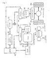
- Fig. 1 is a schematic diagram showing a series hybrid vehicle, to which a warm up control device of a hybrid electric vehicle according to the present invention is applied.
- a warm up control device of the hybrid electric vehicle according to the present invention is applied.
- a large vehicle such as an omnibus, which runs at a low speed in a city, is supposed to be the series hybrid vehicle.
- the series hybrid vehicle is equipped with a traction motor 10 as a source of driving force.
- the traction motor 10 is electrically connected to a high-voltage secondary battery 12, which supplies power, through an inverter 14.
- the traction motor 10 is, e.g., an induction motor, but may also be a permanent electromagnet synchronous type motor.
- the traction motor 10 When the vehicle is braked, the traction motor 10 functions as an energy regenerative brake, i.e., a generator that utilizes braking energy. More specifically, when a driver of the vehicle operates a brake (not shown), the traction motor 10 generates a braking force and power at the same time. The generated power is charged in the battery 12.
- the inverter 14 supplies stable power to the traction motor 10 by adjusting a voltage and a current supplied from the battery 12 or a later-described generator 22, or supplies stable power to the battery 12 by adjusting a voltage and a current generated by the traction motor 10.
- a pair of driving wheels WR, WL is connected to a rotary shaft of the traction motor 10 through reduction gears 16 and a differential gear 18.
- the reduction gears 16 are not necessarily always provided.
- the battery 12 and the inverter 14 are electrically connected to the generator 22 through the other inverter 20.
- a rotary shaft of the generator 22 is connected to an output shaft of an engine 24, which is an internal combustion engine for generator.
- the generator 22 is, i.e., a permanent electromagnet type generator.
- the inverter 20 is also electrically connected to an auxiliary motor 26, which drives auxiliaries such as an air compressor 27 for an air brake and a power steering pump 28.
- the inverter 20 supplies stable power to the battery 12 or the traction motor 10 by adjusting a voltage and a current generated by the generator 22, or supplies stable power to the auxiliary motor 26 by adjusting the voltage and the current from the battery 12.
- the inverter 20 also has a function of adjusting the voltage and the current from the battery 12 and supplying them to the generator 22.
- a relay fuse 30 is mounted between the battery 12 and the inverters 14, 20.
- the relay fuse 30 is electrically connected to the inverter 14, and allows a current to flow from the battery 12 to the traction motor 10 or prevents an excessive current from flowing from the battery 12 to the traction motor 10 in accordance with information from the inverter 14.
- the relay fuse 30 also has a function of preventing the generator 22 or traction motor 10 during the regenerative braking (the engine regeneration) from excessively charging the battery 12.
- the battery 12 and the inverters 14, 20 are electrically connected to an electronic control unit (ECU) 40 so that the battery 12 and the inverter 14, 20 can communicate with the ECU 40.
- the inverter 14 and the inverter 20 are electrically connected to the traction motor 10 and the generator 22, respectively, so that they can communicate with one another.
- the ECU 40 is connected to a battery controller 46, which monitors a charging level (SOC: state of charging), etc. of the battery 12, and an engine controller 48, which controls the operation of the engine 24.
- the engine controller 48 also has a function of sensing an engine revolution speed Ne and sensing an engine temperature Te from a coolant temperature of the engine 24 (a temperature sensing device).
- a required motor torque signal corresponding to a control input of an accelerator pedal (not shown) is supplied to the inverter 14 while the vehicle is running.
- the inverter 14 adjusts the voltage and the current from the battery 12, and therefore, the traction motor 10 generates a desired motor torque.
- the battery controller 46 senses a drop in SOC of the battery 12
- the engine controller 48 starts the engine 24 to operate the generator 22, which generates power to charge the battery 12 in accordance with SOC. If SOC of the battery 12 is low, the power equivalent to a power consumption of the traction motor 10 is directly fed from the generator 22 to the traction motor 10 so that the surplus power from the generator 22 can be charged in the battery 12.
- a brake pedal (not shown) is operated to brake the vehicle and the control input of the accelerator pedal is zero, the traction motor 10 performs the regenerative braking and generates power to charge the battery 12. While the vehicle is running, the power from the battery 12 appropriately runs the auxiliary motor 26 in order to drive the auxiliaries such as the compressor 27 and the power steering pump 28.
- the engine 24 is started to cause the generator 22 to generate the power as stated above. If, however, the engine 24 is static for a long period of time, the engine 24 becomes cold. Thus, the engine 24 must be warmed up in order to acquire a stable output.
- the warm-up control device in the hybrid electric vehicle i.e., the warm-up control for the engine 24.
- Fig. 2 is a flow chart showing a control routine of the warm-up control according to the present invention, which is executed by the ECU 40. A description will hereunder be given with reference to the flow chart.
- step S12 it is determined whether the engine temperature Te is higher than a preset temperature (Tw) (Te>Tw) or not in accordance with the engine temperature information Te from the engine controller 48. If yes, the process goes out of the routine. If no, the process goes to a step S14.
- Tw preset temperature
- step S14 it is determined whether the engine temperature Te is higher than a first preset first temperature Twa (Twa ⁇ Tw) (Te ⁇ Twa) or not. If yes, i.e., the engine temperature Te is determined as being higher than the first preset temperature Twa and being not greater than the set temperature Tw, the process goes to a step S16.
- a small power generation load is applied. More specifically, a load equivalent to a small power generation (the first set load) is applied to the engine 24 to thereby warm up the engine 24.
- the small power generation load (the first set load) is applied to the generator 22 in order to cause the generator 22 to generate a small amount of power.
- the engine controller 48 issues an engine output command to the engine 24 in order to maintain the engine revolution speed Ne at a predetermine low revolution speed Nel (e.g., 500rpm) against the small power generation load (the first set load) of the generator 22.
- a fuel injection information is supplied to a fuel injection valve (not shown) of the engine 24 in order to make it possible to maintain the engine revolution speed Ne at the predetermined low revolution speed Nel against the small power generation load (the first set load) of the generator 22.
- the engine 24 injects a larger quantity of fuel from the fuel injection valve than fuel required for operating the unloaded generator 22 to thereby achieve an engine output in opposition to the small power generation load (the first set load) of the generator 22 although the engine revolution speed Ne is as low as the predetermined low revolution speed Nel.
- This generates a large amount of combustion heat, and facilitates the warm-up of the engine 24.
- loading the generator 22 makes it possible to warm up the engine 24 more quickly within a shorter period than in the case where the unloaded generator 22 is operated. In this case, there is no necessity of raising the engine revolution speed Ne.
- the engine revolution speed Ne is maintained at the predetermined low revolution speed Nel (e.g., 500rpm) during the warm-up of the engine 24, the engine 24 can be kept quiet with reduced noise and vibration. Moreover, it is possible to prevent each sliding part of the engine 24 from being damaged by the increase in the engine revolution speed in the case where the engine 24 is cold and is not completely smooth. This extends the life of the engine 24.
- Nel e.g. 500rpm
- the warm-up control device of the present invention can warm up the engine 24 while extending the life of the engine 24.
- a next step S28 it is determined whether or not the engine temperature Te is higher than a second predetermined temperature Twe (Twe>Tw) preset as a warm-up completion temperature (Te>Twe). If no, the warm-up of the engine 24 is continued in a step S16. If yes, the process goes to a step S24 where it is determined that the warm-up is completed and the application of the power generation load is finished.
- step S20 a medium power generation load (the second set load) is applied. More specifically, a load equivalent to a medium power generation (the second set load) is applied to the engine 24 to thereby warm up the engine 24.
- the medium power generation load (the second set load) higher than the small power generation load (the first set load) is applied to the generator 22 to cause the generator 22 to generate medium power.
- the engine controller 48 issues an engine output command to the engine 24 in order to maintain the engine revolution speed Ne at a predetermine low revolution speed Nel (e.g., 500rpm) against the medium power generation load (the second set load).
- fuel injection information is supplied to a fuel injection valve (not shown) of the engine 24 in order to make it possible to maintain the engine revolution speed Ne at the predetermined low revolution speed Nel against the medium power generation load (the second set load) of the generator 22.
- the engine 24 injects a larger quantity of fuel from the fuel injection valve than fuel required for operating the unloaded generator 22 to thereby achieve an engine output in opposition to the medium power generation load (the second set load) of the generator 22 although the engine revolution speed Ne is as low as the predetermined low revolution speed Ne1. This generates a large amount of combustion heat, and facilitates the warm-up of the engine 24.
- the medium power generation (the second set load) higher than the small power generation (the first set load) is applied to the generator 22, and the engine 24 is controlled so as to maintain the engine revolution speed Ne at the predetermined low revolution speed Nel.
- step S18 it is determined in a step S22 whether the engine temperature Te is higher than the second predetermined temperature Twe (Te>Twe) or not. If no, the warm-up of the engine 24 is continued in the step S20. If no, the process goes to the step S24 where it is determined that the warm-up is completed. Accordingly, the application of the power generation load is finished.
- Twe the second predetermined temperature
- the engine revolution speed Ne is raised from the predetermined revolution speed Nel as is normal to cause the generator 22 to start generating the power.
- the load of the generator 22 can be divided into the following two stages: the small power generation load equivalent to the small power generation the first set load) and the medium power generation load equivalent to the medium power generation (the second set load).
- the load of the generator 22 may be changed in a plurality of stages according to the engine temperature Te, and accordingly, the engine 24 may be controlled so as to maintain the engine revolution speed Ne at the predetermined low revolution speed Ne1.
- whether the engine is cold or not is determined according to the engine temperature.
- the present invention should not be restricted to this.
- whether the engine is cold or not may be determined according to a period from the stop to the start of the engine.
Landscapes
- Engineering & Computer Science (AREA)
- Combustion & Propulsion (AREA)
- Chemical & Material Sciences (AREA)
- Mechanical Engineering (AREA)
- Transportation (AREA)
- Sustainable Energy (AREA)
- Power Engineering (AREA)
- Life Sciences & Earth Sciences (AREA)
- Sustainable Development (AREA)
- General Engineering & Computer Science (AREA)
- Automation & Control Theory (AREA)
- Electric Propulsion And Braking For Vehicles (AREA)
- Control Of Vehicle Engines Or Engines For Specific Uses (AREA)
- Hybrid Electric Vehicles (AREA)
Applications Claiming Priority (2)
| Application Number | Priority Date | Filing Date | Title |
|---|---|---|---|
| JP2000038602A JP2001227374A (ja) | 2000-02-16 | 2000-02-16 | ハイブリッド電気自動車の暖機制御装置 |
| JP2000038602 | 2000-02-16 |
Publications (3)
| Publication Number | Publication Date |
|---|---|
| EP1127733A2 true EP1127733A2 (fr) | 2001-08-29 |
| EP1127733A3 EP1127733A3 (fr) | 2002-04-17 |
| EP1127733B1 EP1127733B1 (fr) | 2004-05-12 |
Family
ID=18562314
Family Applications (1)
| Application Number | Title | Priority Date | Filing Date |
|---|---|---|---|
| EP01103474A Expired - Lifetime EP1127733B1 (fr) | 2000-02-16 | 2001-02-14 | Dispositif de commande de préchauffage pour un véhicule hybride |
Country Status (4)
| Country | Link |
|---|---|
| US (1) | US6459166B2 (fr) |
| EP (1) | EP1127733B1 (fr) |
| JP (1) | JP2001227374A (fr) |
| DE (1) | DE60103195T2 (fr) |
Cited By (8)
| Publication number | Priority date | Publication date | Assignee | Title |
|---|---|---|---|---|
| EP1382475A1 (fr) * | 2002-07-19 | 2004-01-21 | Toyota Jidosha Kabushiki Kaisha | Véhicule hybride et procédé de préchauffage pour le démarrage d'un moteur à combustion |
| WO2005032875A1 (fr) | 2003-09-25 | 2005-04-14 | Government Of The United States Of America, As Represented By The Administrator Of The U.S. Environmental Protection Agency | Procede de fonctionnement d'un vehicule hybride en serie |
| EP1672205A1 (fr) * | 2004-12-17 | 2006-06-21 | Renault s.a.s. | Procédé et dispositif de mise en condition d'un moteur de véhicule automobile en vue d'une régénération de filtre à particules |
| EP2211045A3 (fr) * | 2001-09-04 | 2010-11-24 | Toyota Jidosha Kabushiki Kaisha | Dispositif de purification des gaz d'échappement d'un moteur |
| WO2012022455A1 (fr) * | 2010-08-16 | 2012-02-23 | Avl List Gmbh | Procédé pour démarrer la génération d'électricité interne dans un véhicule électrique |
| WO2013106648A1 (fr) * | 2012-01-13 | 2013-07-18 | Chrysler Group Llc | Procédé pour accélérer le réchauffement du compartiment à passagers en cas de démarrage à distance d'un moteur à combustion interne |
| WO2014070086A1 (fr) | 2012-11-01 | 2014-05-08 | Scania Cv Ab | Procédé de chauffage d'un composant de véhicule par augmentation d'une charge d'un moteur avec une force de freinage |
| EP2914467A4 (fr) * | 2012-11-01 | 2016-07-06 | Scania Cv Ab | Procédé de chauffage d'un composant de véhicule par augmentation d'une charge d'un moteur avec une force de freinage |
Families Citing this family (40)
| Publication number | Priority date | Publication date | Assignee | Title |
|---|---|---|---|---|
| JP3969623B2 (ja) * | 2000-06-30 | 2007-09-05 | 本田技研工業株式会社 | エンジン駆動発電装置 |
| EP1186463A1 (fr) * | 2000-08-28 | 2002-03-13 | Siemens Aktiengesellschaft | Méthode pour actionner l'entraínement d'une machine à combustion interne et d'une machine électrique |
| DE10108909B4 (de) * | 2001-02-23 | 2010-11-04 | Linde Material Handling Gmbh | Verfahren zum Betreiben eines Fahrzeugs mit einem elektrischen Fahrmotor |
| US20020179348A1 (en) * | 2001-05-30 | 2002-12-05 | Goro Tamai | Apparatus and method for controlling a hybrid vehicle |
| US6612386B2 (en) * | 2001-05-30 | 2003-09-02 | General Motors Corporation | Apparatus and method for controlling a hybrid vehicle |
| JP3573206B2 (ja) * | 2002-03-12 | 2004-10-06 | トヨタ自動車株式会社 | 車両制御装置 |
| JP2003335126A (ja) * | 2002-05-17 | 2003-11-25 | Mitsubishi Electric Corp | 車両用空気調和機 |
| JP3775351B2 (ja) * | 2002-06-12 | 2006-05-17 | 株式会社デンソー | ハイブリッドコンプレッサ装置およびハイブリッドコンプレッサの制御方法 |
| EP1568739B1 (fr) | 2002-12-05 | 2009-08-26 | Tokuyama Corporation | Preparation de revetement et article optique |
| US6998727B2 (en) | 2003-03-10 | 2006-02-14 | The United States Of America As Represented By The Administrator Of The Environmental Protection Agency | Methods of operating a parallel hybrid vehicle having an internal combustion engine and a secondary power source |
| US7122914B2 (en) * | 2003-12-22 | 2006-10-17 | Caterpillar Inc. | System for starting an electric drive machine engine |
| US7335999B2 (en) * | 2004-06-15 | 2008-02-26 | Honeywell International, Inc. | Fluid actuated rotating device including a low power generator |
| WO2006039520A1 (fr) * | 2004-09-30 | 2006-04-13 | Mtd Products Inc. | Vehicule utilitaire hybride |
| JP2007099223A (ja) * | 2005-10-07 | 2007-04-19 | Toyota Motor Corp | ハイブリッド自動車 |
| JP4358178B2 (ja) * | 2005-10-26 | 2009-11-04 | トヨタ自動車株式会社 | エンジンの始動制御装置 |
| DE102006003424A1 (de) * | 2006-01-24 | 2007-08-02 | Webasto Ag | Kraftfahrzeug mit Solarmodul |
| JP5001566B2 (ja) * | 2006-03-23 | 2012-08-15 | 三菱ふそうトラック・バス株式会社 | 電気自動車の制御装置 |
| JP4245624B2 (ja) * | 2006-09-20 | 2009-03-25 | トヨタ自動車株式会社 | ハイブリッド車両の電源制御装置および電源制御方法 |
| US8020652B2 (en) | 2007-12-04 | 2011-09-20 | Ford Global Technologies, Llc | Generator power-based cold start strategy |
| US8125180B2 (en) * | 2008-05-12 | 2012-02-28 | Ford Global Technologies, Llc | Integrated side view mirror assembly and electrical port for an automotive vehicle |
| US8113308B2 (en) * | 2008-07-02 | 2012-02-14 | Illinois Institute Of Technology | Integrated electric motor differential for hybrid electric vehicles |
| JP4450095B2 (ja) * | 2008-07-11 | 2010-04-14 | トヨタ自動車株式会社 | ハイブリッド車両の制御システム及び制御方法 |
| KR20110086001A (ko) * | 2008-09-26 | 2011-07-27 | 에이알비 그린파워, 엘엘씨 | 하이브리드 에너지 변환 시스템 |
| US20100140244A1 (en) * | 2008-12-08 | 2010-06-10 | Ford Global Technologies, Llc | Integrated side view mirror assembly and electrical port for an automotive vehicle |
| US10279684B2 (en) * | 2008-12-08 | 2019-05-07 | Ford Global Technologies, Llc | System and method for controlling heating in a hybrid vehicle using a power source external to the hybrid vehicle |
| US8237300B2 (en) * | 2008-12-19 | 2012-08-07 | Caterpillar Inc. | Genset power system having multiple modes of operation |
| JP4877382B2 (ja) * | 2009-11-20 | 2012-02-15 | トヨタ自動車株式会社 | ハイブリッド自動車およびその制御方法 |
| US8536729B2 (en) * | 2010-06-09 | 2013-09-17 | Hamilton Sundstrand Corporation | Hybrid electric power architecture for a vehicle |
| WO2012053068A1 (fr) * | 2010-10-20 | 2012-04-26 | トヨタ自動車株式会社 | Véhicule, procédé de commande pour groupe motopropulseur, et appareil de commande pour groupe motopropulseur |
| US8602143B2 (en) * | 2011-03-17 | 2013-12-10 | GM Global Technology Operations LLC | Electric vehicle with range-extending engine and climate control compressor |
| JP5794030B2 (ja) * | 2011-08-08 | 2015-10-14 | マツダ株式会社 | ハイブリッド自動車の制御装置 |
| DE102011110907B4 (de) * | 2011-08-18 | 2016-10-20 | Audi Ag | Verfahren zum Betreiben einer Hybridantriebsvorrichtung eines Kraftfahrzeugs sowie Hybridantriebsvorrichtung |
| CN103863300B (zh) * | 2012-12-07 | 2016-08-24 | 北汽福田汽车股份有限公司 | 一种增程式电动车的控制方法 |
| CN104044475B (zh) * | 2013-03-15 | 2017-07-11 | 通用电气公司 | 改进的驱动系统以及使用该驱动系统的装置 |
| JP5958457B2 (ja) * | 2013-12-13 | 2016-08-02 | トヨタ自動車株式会社 | ハイブリッド車両 |
| JP6159681B2 (ja) | 2014-05-07 | 2017-07-05 | 日立建機株式会社 | ハイブリッド作業機械 |
| US9708950B2 (en) * | 2015-02-26 | 2017-07-18 | Cummins Power Generation Ip, Inc. | Genset engine using electrical sensing to control components for optimized performance |
| JP6354687B2 (ja) * | 2015-07-14 | 2018-07-11 | マツダ株式会社 | 車両の制御装置 |
| JP6319241B2 (ja) * | 2015-09-11 | 2018-05-09 | マツダ株式会社 | 発電機駆動用エンジン搭載の自動車 |
| JP6278029B2 (ja) * | 2015-10-30 | 2018-02-14 | マツダ株式会社 | 発電機駆動用エンジン搭載の自動車 |
Citations (1)
| Publication number | Priority date | Publication date | Assignee | Title |
|---|---|---|---|---|
| JPH05328528A (ja) | 1992-05-25 | 1993-12-10 | Toyota Motor Corp | ハイブリッド車のエンジン駆動発電機の制御装置 |
Family Cites Families (10)
| Publication number | Priority date | Publication date | Assignee | Title |
|---|---|---|---|---|
| US4489242A (en) * | 1981-01-22 | 1984-12-18 | Worst Marc T | Stored power system for vehicle accessories |
| JPH0297300A (ja) * | 1988-09-30 | 1990-04-09 | Aisin Seiki Co Ltd | 可搬式エンジン発電装置 |
| DE4133059A1 (de) * | 1991-10-04 | 1993-04-08 | Mannesmann Ag | Antriebsanordnung fuer ein kraftfahrzeug |
| JP2738819B2 (ja) * | 1994-08-22 | 1998-04-08 | 本田技研工業株式会社 | ハイブリッド車両の発電制御装置 |
| DE19505431B4 (de) * | 1995-02-17 | 2010-04-29 | Bayerische Motoren Werke Aktiengesellschaft | Leistungssteuersystem für Kraftfahrzeuge mit einer Mehrzahl von leistungsumsetzenden Komponenten |
| JP3230438B2 (ja) * | 1996-06-10 | 2001-11-19 | トヨタ自動車株式会社 | ハイブリッド型車両の触媒温度制御装置 |
| GB9714132D0 (en) * | 1997-07-05 | 1997-09-10 | Rover Group | Catalyst temperature control in hybrid vehicles |
| JP3285531B2 (ja) * | 1998-03-20 | 2002-05-27 | 三菱電機株式会社 | モータジェネレータ搭載エンジンの始動装置 |
| JP3644298B2 (ja) * | 1999-03-31 | 2005-04-27 | スズキ株式会社 | モータ駆動制御装置 |
| US6394210B2 (en) * | 1999-06-07 | 2002-05-28 | Mitsubishi Heavy Industries, Ltd. | Temperature controller for vehicular battery |
-
2000
- 2000-02-16 JP JP2000038602A patent/JP2001227374A/ja active Pending
-
2001
- 2001-02-14 DE DE60103195T patent/DE60103195T2/de not_active Expired - Fee Related
- 2001-02-14 EP EP01103474A patent/EP1127733B1/fr not_active Expired - Lifetime
- 2001-02-16 US US09/784,037 patent/US6459166B2/en not_active Expired - Fee Related
Patent Citations (1)
| Publication number | Priority date | Publication date | Assignee | Title |
|---|---|---|---|---|
| JPH05328528A (ja) | 1992-05-25 | 1993-12-10 | Toyota Motor Corp | ハイブリッド車のエンジン駆動発電機の制御装置 |
Cited By (13)
| Publication number | Priority date | Publication date | Assignee | Title |
|---|---|---|---|---|
| EP2211045A3 (fr) * | 2001-09-04 | 2010-11-24 | Toyota Jidosha Kabushiki Kaisha | Dispositif de purification des gaz d'échappement d'un moteur |
| EP1382475A1 (fr) * | 2002-07-19 | 2004-01-21 | Toyota Jidosha Kabushiki Kaisha | Véhicule hybride et procédé de préchauffage pour le démarrage d'un moteur à combustion |
| US7077224B2 (en) | 2002-07-19 | 2006-07-18 | Toyota Jidosha Kabushiki Kaisha | Hybrid vehicle and method of controlling the same |
| WO2005032875A1 (fr) | 2003-09-25 | 2005-04-14 | Government Of The United States Of America, As Represented By The Administrator Of The U.S. Environmental Protection Agency | Procede de fonctionnement d'un vehicule hybride en serie |
| AU2004278296B2 (en) * | 2003-09-25 | 2011-03-10 | Government Of The United States Of America, As Represented By The Administrator Of The U.S. Environmental Protection Agency | Methods of operating a series hybrid vehicle |
| FR2879670A1 (fr) * | 2004-12-17 | 2006-06-23 | Renault Sas | Procede et dispositif de mise en condition d'un moteur de vehicule automobile en vue d'une regeneration de filtre a particules |
| EP1672205A1 (fr) * | 2004-12-17 | 2006-06-21 | Renault s.a.s. | Procédé et dispositif de mise en condition d'un moteur de véhicule automobile en vue d'une régénération de filtre à particules |
| WO2012022455A1 (fr) * | 2010-08-16 | 2012-02-23 | Avl List Gmbh | Procédé pour démarrer la génération d'électricité interne dans un véhicule électrique |
| CN103153684A (zh) * | 2010-08-16 | 2013-06-12 | 李斯特内燃机及测试设备公司 | 用于在电动汽车中启动内部发电机的方法 |
| CN103153684B (zh) * | 2010-08-16 | 2016-01-20 | 李斯特内燃机及测试设备公司 | 用于在电动汽车中启动内部发电机的方法 |
| WO2013106648A1 (fr) * | 2012-01-13 | 2013-07-18 | Chrysler Group Llc | Procédé pour accélérer le réchauffement du compartiment à passagers en cas de démarrage à distance d'un moteur à combustion interne |
| WO2014070086A1 (fr) | 2012-11-01 | 2014-05-08 | Scania Cv Ab | Procédé de chauffage d'un composant de véhicule par augmentation d'une charge d'un moteur avec une force de freinage |
| EP2914467A4 (fr) * | 2012-11-01 | 2016-07-06 | Scania Cv Ab | Procédé de chauffage d'un composant de véhicule par augmentation d'une charge d'un moteur avec une force de freinage |
Also Published As
| Publication number | Publication date |
|---|---|
| EP1127733A3 (fr) | 2002-04-17 |
| EP1127733B1 (fr) | 2004-05-12 |
| DE60103195T2 (de) | 2005-05-25 |
| US6459166B2 (en) | 2002-10-01 |
| US20010013702A1 (en) | 2001-08-16 |
| JP2001227374A (ja) | 2001-08-24 |
| DE60103195D1 (de) | 2004-06-17 |
Similar Documents
| Publication | Publication Date | Title |
|---|---|---|
| EP1127733B1 (fr) | Dispositif de commande de préchauffage pour un véhicule hybride | |
| JP3876979B2 (ja) | バッテリ制御装置 | |
| US7937195B2 (en) | System for managing a power source in a vehicle | |
| US20050061563A1 (en) | Method and system of requesting engine on/off state in hybrid electric vehicle | |
| CN103702881B (zh) | 车辆和车辆的控制方法 | |
| JP2003219564A (ja) | 車両における蓄電装置の制御装置 | |
| CN101456416A (zh) | 用于插入式混合电动车的充电损耗能量管理策略 | |
| US20190283730A1 (en) | Control system for hybrid vehicle | |
| JP3642249B2 (ja) | ハイブリッド電気自動車のエンジン始動制御装置 | |
| US7425769B2 (en) | Engine start method of vehicle having starter motor and ISG | |
| US7301245B2 (en) | Control system for a vehicle power supply and control method thereof | |
| CN102042099A (zh) | 用于在车辆中优化发动机空转速度的方法及设备 | |
| CN102026836B (zh) | 用于混合动力车的电力驱动模式选择 | |
| JP3047621B2 (ja) | ハイブリッド車のエンジン駆動発電機の制御装置 | |
| JP2020192897A (ja) | ハイブリッド車両の制御装置 | |
| JP2973657B2 (ja) | シリーズハイブリッド車における電力配分装置 | |
| JP3374720B2 (ja) | ハイブリッド車両の制御装置 | |
| JP2000161099A (ja) | 内燃機関の冷却制御装置 | |
| US20210394741A1 (en) | Hybrid vehicle and method for controlling hybrid vehicle | |
| JP2022084429A (ja) | ハイブリッド車両の制御装置 | |
| KR100493219B1 (ko) | 차량용 전원의 제어장치 | |
| EP1288051B1 (fr) | Système de régulation pour un véhicule hybride à moteur diesel | |
| KR102546717B1 (ko) | 마일드 하이브리드 차량의 연료분사 제어 방법 | |
| JP7753275B2 (ja) | ハイブリッド車両の制御装置 | |
| JP7768103B2 (ja) | ハイブリッド車両の制御装置 |
Legal Events
| Date | Code | Title | Description |
|---|---|---|---|
| PUAI | Public reference made under article 153(3) epc to a published international application that has entered the european phase |
Free format text: ORIGINAL CODE: 0009012 |
|
| 17P | Request for examination filed |
Effective date: 20010313 |
|
| AK | Designated contracting states |
Kind code of ref document: A2 Designated state(s): DE SE Kind code of ref document: A2 Designated state(s): AT BE CH CY DE DK ES FI FR GB GR IE IT LI LU MC NL PT SE TR |
|
| AX | Request for extension of the european patent |
Free format text: AL;LT;LV;MK;RO;SI |
|
| PUAL | Search report despatched |
Free format text: ORIGINAL CODE: 0009013 |
|
| AK | Designated contracting states |
Kind code of ref document: A3 Designated state(s): AT BE CH CY DE DK ES FI FR GB GR IE IT LI LU MC NL PT SE TR |
|
| AX | Request for extension of the european patent |
Free format text: AL;LT;LV;MK;RO;SI |
|
| RIC1 | Information provided on ipc code assigned before grant |
Free format text: 7B 60K 41/00 A, 7B 60L 11/12 B |
|
| 17Q | First examination report despatched |
Effective date: 20020805 |
|
| AKX | Designation fees paid |
Free format text: DE SE |
|
| RAP1 | Party data changed (applicant data changed or rights of an application transferred) |
Owner name: MITSUBISHI FUSO TRUCK AND BUS CORPORATION |
|
| RIC1 | Information provided on ipc code assigned before grant |
Ipc: 7B 60K 6/04 B Ipc: 7B 60L 11/12 B Ipc: 7B 60K 41/00 A |
|
| GRAP | Despatch of communication of intention to grant a patent |
Free format text: ORIGINAL CODE: EPIDOSNIGR1 |
|
| GRAS | Grant fee paid |
Free format text: ORIGINAL CODE: EPIDOSNIGR3 |
|
| GRAA | (expected) grant |
Free format text: ORIGINAL CODE: 0009210 |
|
| AK | Designated contracting states |
Kind code of ref document: B1 Designated state(s): DE SE |
|
| REG | Reference to a national code |
Ref country code: IE Ref legal event code: FG4D |
|
| REF | Corresponds to: |
Ref document number: 60103195 Country of ref document: DE Date of ref document: 20040617 Kind code of ref document: P |
|
| REG | Reference to a national code |
Ref country code: SE Ref legal event code: TRGR |
|
| PLBE | No opposition filed within time limit |
Free format text: ORIGINAL CODE: 0009261 |
|
| STAA | Information on the status of an ep patent application or granted ep patent |
Free format text: STATUS: NO OPPOSITION FILED WITHIN TIME LIMIT |
|
| 26N | No opposition filed |
Effective date: 20050215 |
|
| PGFP | Annual fee paid to national office [announced via postgrant information from national office to epo] |
Ref country code: DE Payment date: 20090213 Year of fee payment: 9 |
|
| PGFP | Annual fee paid to national office [announced via postgrant information from national office to epo] |
Ref country code: SE Payment date: 20090206 Year of fee payment: 9 |
|
| EUG | Se: european patent has lapsed | ||
| PG25 | Lapsed in a contracting state [announced via postgrant information from national office to epo] |
Ref country code: DE Free format text: LAPSE BECAUSE OF NON-PAYMENT OF DUE FEES Effective date: 20100901 |
|
| PG25 | Lapsed in a contracting state [announced via postgrant information from national office to epo] |
Ref country code: SE Free format text: LAPSE BECAUSE OF NON-PAYMENT OF DUE FEES Effective date: 20100215 |