EP1127812A1 - Dispositif de transfert de marchandises en colis - Google Patents
Dispositif de transfert de marchandises en colis Download PDFInfo
- Publication number
- EP1127812A1 EP1127812A1 EP01102896A EP01102896A EP1127812A1 EP 1127812 A1 EP1127812 A1 EP 1127812A1 EP 01102896 A EP01102896 A EP 01102896A EP 01102896 A EP01102896 A EP 01102896A EP 1127812 A1 EP1127812 A1 EP 1127812A1
- Authority
- EP
- European Patent Office
- Prior art keywords
- brake
- transport
- transport device
- piece goods
- brake beam
- Prior art date
- Legal status (The legal status is an assumption and is not a legal conclusion. Google has not performed a legal analysis and makes no representation as to the accuracy of the status listed.)
- Withdrawn
Links
- 230000005540 biological transmission Effects 0.000 description 4
- 238000009825 accumulation Methods 0.000 description 3
- 230000007246 mechanism Effects 0.000 description 2
- 230000007704 transition Effects 0.000 description 2
- 230000001133 acceleration Effects 0.000 description 1
- 239000000969 carrier Substances 0.000 description 1
- 238000010276 construction Methods 0.000 description 1
- 230000001419 dependent effect Effects 0.000 description 1
- 238000001514 detection method Methods 0.000 description 1
- 230000005484 gravity Effects 0.000 description 1
- 239000000463 material Substances 0.000 description 1
- 230000007935 neutral effect Effects 0.000 description 1
- 230000003287 optical effect Effects 0.000 description 1
- 239000000523 sample Substances 0.000 description 1
- 230000001953 sensory effect Effects 0.000 description 1
Images


Classifications
-
- B—PERFORMING OPERATIONS; TRANSPORTING
- B65—CONVEYING; PACKING; STORING; HANDLING THIN OR FILAMENTARY MATERIAL
- B65G—TRANSPORT OR STORAGE DEVICES, e.g. CONVEYORS FOR LOADING OR TIPPING, SHOP CONVEYOR SYSTEMS OR PNEUMATIC TUBE CONVEYORS
- B65G11/00—Chutes
- B65G11/20—Auxiliary devices, e.g. for deflecting, controlling speed of, or agitating articles or solids
- B65G11/203—Auxiliary devices, e.g. for deflecting, controlling speed of, or agitating articles or solids for articles
Definitions
- the invention relates to a transport device for General cargo, according to the preamble of claim 1.
- Such transport devices are known in various embodiments and are described in detail, for example, in DE 43 09 222 A1, DE 34 18 205 C2, DE 41 11 154 C2 or EP 0 698 568 A1.
- Such transport devices often have rotating conveying means, for example in the form of a conveyor belt, in the area of their "normal" conveyor routes or have drivable transport rollers in these transport sections.
- rotating conveying means for example in the form of a conveyor belt, in the area of their "normal" conveyor routes or have drivable transport rollers in these transport sections.
- these known transport devices are also often equipped with devices for low-pressure or low-pressure storage of the conveyed goods.
- the accumulation path described in DE 43 09 222 A1 has, for example, a rigid end stop arranged at the end of the accumulation path and a stop device arranged in the conveying direction before the end stop.
- the stop device is attached to one end of a rocker running below the conveying plane between the rigid end stop and the stop device. At the other end of the rocker, a run-up slope that rises in the direction of the end stop and ends in the lowered position of the stop device above the conveying plane is fastened.
- DE 34 18 205 C2 relates to an accumulation roller conveyor with conveyor rollers arranged between parallel side carriers, each of which is connected to a continuously rotating drive element via a slip clutch.
- the entire system is divided into segments that are the same as each other.
- a sensor At the top of each segment is a sensor which can be pivoted under the weight of the material to be conveyed and which controls a brake shoe arranged at the end of each segment.
- a similar device for the storage of piece goods without back pressure is also described in DE 41 11 154 C2.
- This known device has conveyor tracks with a continuously rotating conveyor.
- lifting plates are provided in corresponding storage locations which, under the action of a lifting device, execute a stroke inclined upwards in the conveying direction of the goods to be conveyed.
- guides are attached to the support profile with inclined upward sloping surfaces on which the lifting plates are slidably mounted. The direction of action of the lifting means is directed parallel to the sliding surfaces.
- a touch probe is also attached to the lifting plate, which is actuated by the conveyed goods.
- EP 0 698 568 A2 describes, for example, a device for recognizing conveyed goods on conveyor tracks, in particular packaged goods on roller conveyors, on which the packaged goods can be moved individually or in blocks.
- the device which works with transmission beams, is connected to electromagnetic valves for controlling lifting and / or actuating drives of individual conveying elements. Between the conveyor elements, a block is arranged at a distance of a storage space length, which consists of a light sensor and an electromagnetic valve, which are connected to one another via a switching or control logic.
- the known devices are not designed and not suitable for use on slopes.
- downward gradients result when piece goods have to be transferred from a higher-level transport device to a lower-lying transport device.
- the cargo In the area of the inclined connecting section, the cargo is then generally accelerated.
- transport speeds of the individual piece goods are not least dependent on the weight of the piece goods.
- major problems can arise when they run onto the downstream transport device.
- the The invention is therefore based on the object of a transport device for general cargo to create a hassle-free transfer goods of different weights over sloping Connections possible.
- the transport device according to the invention enables in simple way that each one is on a downhill slope General cargo located on the route section is initially sensory detected and then automatically according to his Condition, especially its current weight-related speed, is braked specifically. That is, by the braking device according to the invention, with in Recesses of a brake slide pivotally mounted Brake beam, it is ensured that all general cargo, regardless of their size and weight, with one predeterminable speed to a subordinate Transport device are transferred.
- the brake chute advantageously has the design described in claim 2. Through targeted control of the individual brake beam rows, it is possible to gently brake both relatively light piece goods and piece goods with a relatively high weight to a predetermined, optimal transfer speed.
- the brake bars are each around one arranged at the front in the direction of transport of the piece goods Swivel axis with limited rotation.
- the brake beams can also via a rear one in the transport direction Switching shaft can be lifted on one side.
- the Brake beam of a row each over a common Switching shaft actuated.
- Such training is simplified and not only cheapens the construction, since only one Thrust piston gear for operating a variety of Brake beam is needed, but also ensures an always even extension and positioning of the brake beam one Line.
- each brake beam row at least one connecting element for a thrust piston gear and a spring element and in the area of the brake beam each Eccentric elements.
- the arrangement is such that the spring element permanently shifts the selector shaft into one position tried to turn, in which the eccentric elements the brake beam lift.
- This torque introduced by the spring element is opposed by a torque which can be initiated by the thrust piston transmission and which, if necessary, fixes the brake bars in a position in which the brake bars are fully or partially retracted.
- This means that the brake bars are always in their braking position without the thrust piston gear being acted upon by the shift shaft.
- the individual thrust piston gears of the brake beam rows are each connected to an overpressure source via separate pneumatic lines.
- Controllable solenoid valves are integrated into the pneumatic lines and are connected to a control device via corresponding control lines. This means that the control device can, depending on corresponding signals from the sensor device, extend or retract the brake bar rows in a defined manner. In this way it is possible to individually adjust the braking force to be applied to the individual piece goods and, for example, to brake very heavily heavy piece goods, while very light piece goods, for example, pass the brake chute almost unchecked.
- a sensor device is arranged at least in front of the first brake beam row, which preferably detects the current speed of the incoming piece goods.
- the solenoid valves arranged in the pneumatic lines are then actuated via the control device and the brake beams are extended or retracted in a targeted manner.
- corresponding sensor devices for determining the Speed of the piece goods are arranged in front of each of the brake beam rows.
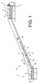
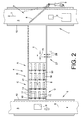
- Figures 1 and 2 show a transport device 1 for Conveying general cargo 2.
- the transport device 1 has thereby, for example, via a T in the direction of transport revolving conveyor belt 3, which, as usual, in one Guide frame 10 supported and by a (not shown) electric motor is driven.
- the transport device 1 is connected via a connecting line in the present embodiment by a downhill Route section 4 is formed with a deeper arranged, preferably the transport device 1 corresponding transport device 5 connected.
- a braking device is integrated, which is preferably designed as a brake slide 6.
- the brake slide 6 is advantageously arranged at the end of the section 4 or the downhill section referred to below as the connecting section 4 is designed overall as a brake slide 6.
- the transport device 1 has a switch 7 which can be controlled in a defined manner in the connection area of the connection section 4.
- This switch 7, which has, for example, a deflector 8 which can be swiveled into the transport path T of the piece goods 2, can be controlled, preferably via a thrust piston gear 9, in such a way that the piece goods 2 are diverted from the transport device 1 via the connecting section 4 to the transport device 5.
- a brake slide 6 is arranged in the end region of the connecting section 4 .
- Such a brake slide 6, which is shown in detail in FIG. 3, has a large number of brake beams 11 which are arranged next to and behind one another and can be controlled in a defined manner and which are pivotably mounted in corresponding recesses 19 in the brake slide 6.
- This means that the brake bars 11 are part of a flat slide surface 20 of the brake slide 6 in the retracted state. In the extended state, the brake bars 11 form ramp-like elevations in this area.
- the individual brake beams 11 are rotatable about a pivot axis 13 stored and lie at their opposite end on one Eccentric disk 14, which is rotatably connected to a selector shaft 15 is arranged.
- this can Spring element 21, however, also directly in that Thrust piston gear 12 are integrated and then ensures ensuring that the brake beams 11 are always issued as soon as the thrust piston gear 12 is depressurized.
- Thrust piston gear 12a-d over corresponding Pneumatic lines 22a-d to a positive pressure source 23 connected.
- Solenoid valves 24a-d preferably 2/2-way valves, turned on, the control lines 25 with a Control device 26 are connected.
- a sensor device 27 is installed in the entrance area of the brake chute 6, which is also connected to the control device 26 via corresponding signal lines 28.
- a sensor device 27 for determining the instantaneous speed of the piece goods 2 can, however, as indicated in the exemplary embodiment with reference to FIG. 3, be installed in front of each of the brake bar rows A, B, C, D.
- an in Area of the connecting section 4 arranged switch 7 controlled. That is, by means of a thrust piston gear 9 For example, a deflector 8 in the in Figures 1 and 2 position shown pivoted. The general cargo 2 is then through the deflector 8 onto the downward connecting section 4 redirected and due to gravity on this route accelerates.
- the current speed of each General cargo 2 determined. Determining the speed takes place preferably, as known, by measuring the Time it takes for the general cargo 2 to be between two To traverse the measuring distance (m).
- the brake beam rows A, B, C, D are then actuated by the control device 26 as a function of the determined speed.
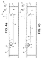
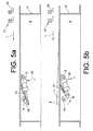
- the control device 26 by appropriately controlling the solenoid valves 24a to 24d, ensures that the thrust piston gears 12a to 12d either pivot the brake bars 11 into a braking position, as indicated in FIGS. 4b and 5b, or, as shown in FIGS. 4a and 5b shown, remain positioned in a neutral transport position below the slide surface 20 of the brake slide 6.
- the ramped brake beam 11, which on their Surface be equipped with a corresponding friction lining can brake the general cargo 2 on one for the transfer of the piece goods 2 onto the subsequent transport device 5 uncritical speed down.
- FIG. 3 is one of the front of each of the brake beam rows A to D.
- a sensor device which directly detects the speed of the piece goods 2
- a sensor device which carries out a weight detection of the piece goods.
- the necessary braking power is calculated in the control device 26.
- a sensor device is also possible which detects a label, a so-called source code, arranged on the piece goods 2.
- the source code contains, for example, information about the weight of the piece goods 2 in question, so that the required braking power of the brake chute 6 can also be easily calculated and sensitively adjusted here.
Landscapes
- Control Of Conveyors (AREA)
- Chutes (AREA)
Applications Claiming Priority (2)
| Application Number | Priority Date | Filing Date | Title |
|---|---|---|---|
| DE2000108300 DE10008300A1 (de) | 2000-02-23 | 2000-02-23 | Transporteinrichtung für Stückgüter |
| DE10008300 | 2000-02-23 |
Publications (1)
| Publication Number | Publication Date |
|---|---|
| EP1127812A1 true EP1127812A1 (fr) | 2001-08-29 |
Family
ID=7632006
Family Applications (1)
| Application Number | Title | Priority Date | Filing Date |
|---|---|---|---|
| EP01102896A Withdrawn EP1127812A1 (fr) | 2000-02-23 | 2001-02-15 | Dispositif de transfert de marchandises en colis |
Country Status (2)
| Country | Link |
|---|---|
| EP (1) | EP1127812A1 (fr) |
| DE (1) | DE10008300A1 (fr) |
Cited By (7)
| Publication number | Priority date | Publication date | Assignee | Title |
|---|---|---|---|---|
| DE102015213195A1 (de) * | 2015-07-14 | 2017-01-19 | Siemens Aktiengesellschaft | Transportrutsche mit Antriebsmittel |
| US20220324658A1 (en) * | 2021-04-09 | 2022-10-13 | Dexterity, Inc. | Robotically-controlled structure to regulate item flow |
| EP4317030A1 (fr) * | 2022-08-05 | 2024-02-07 | Deutsche Post AG | Dispositif de transport d'objets |
| US20240051757A1 (en) * | 2022-08-12 | 2024-02-15 | Marble, Inc. | Variable friction chute |
| CN119018532A (zh) * | 2024-10-29 | 2024-11-26 | 连云港百菇源生物科技有限公司 | 一种新型金针菇原料出库机 |
| US12577058B2 (en) | 2022-08-12 | 2026-03-17 | Marble, Inc. | Spacing and classification conveyors and related systems and methods |
| WO2026074203A1 (fr) * | 2024-10-04 | 2026-04-09 | Interroll Holding Ag | Goulotte de transport |
Families Citing this family (1)
| Publication number | Priority date | Publication date | Assignee | Title |
|---|---|---|---|---|
| DE102009059080A1 (de) * | 2009-12-18 | 2011-06-22 | Schmale, Erhard, 34479 | Verfahren zur Überprüfung der Funktionstüchtigkeit einer Rollenbahn sowie Messanordnung zur Ermittlung der Geschwindigkeit eines auf einer Rollenbahn ablaufenden Gegenstands |
Citations (9)
| Publication number | Priority date | Publication date | Assignee | Title |
|---|---|---|---|---|
| DE3418205C2 (de) | 1984-05-16 | 1986-04-10 | psb GmbH Förderanlagen und Lagertechnik, 6780 Pirmasens | Staurollenförderer |
| EP0521541A1 (fr) * | 1991-07-05 | 1993-01-07 | Vanderlande Industries Nederland B.V. | Colonne de descente munie de moyens de retardement |
| DE4309222A1 (de) | 1992-03-24 | 1993-09-30 | Haro Foerderelemente Hacklaend | Staubahn, insbesondere Rollenbahn für flächige Lager- und/oder Transportgüter mit Vereinzelungseinrichtung |
| DE4111154C2 (de) | 1991-04-06 | 1994-01-05 | Psb Foerderanlagen | Vorrichtung an einer Förderbahn |
| EP0698568A2 (fr) | 1994-08-16 | 1996-02-28 | MANNESMANN Aktiengesellschaft | Dispositif pour détecter des matières à transporter sur convoyeurs, notamment des charges isolées sur convoyeurs à rouleaux |
| DE29802801U1 (de) * | 1998-02-18 | 1998-04-09 | Schlafhorst Produktionstechnik GmbH, 41061 Mönchengladbach | Bremsvorrichtung für eine Schwerkraftrollenbahn |
| EP0882661A1 (fr) * | 1997-06-02 | 1998-12-09 | MANNESMANN Aktiengesellschaft | Convoyeur à rouleaux par gravité à rouleaux supports freinés et méthode pour son fonctionnnement |
| EP0885822A1 (fr) * | 1997-06-18 | 1998-12-23 | MANNESMANN Aktiengesellschaft | Transporteur actionné par gravité à rouleaux supports freinés et son mode de fonctionnement |
| BE1011345A3 (nl) * | 1997-09-01 | 1999-07-06 | Egemin Nv | Inrichting voor het transport van voorwerpen. |
Family Cites Families (4)
| Publication number | Priority date | Publication date | Assignee | Title |
|---|---|---|---|---|
| GB8708199D0 (en) * | 1987-04-06 | 1987-05-13 | Fenlon R | Conveyor belt assembly |
| DE3817388C1 (fr) * | 1988-05-19 | 1989-07-06 | Mannesmann Ag, 4000 Duesseldorf, De | |
| DE19636024C2 (de) * | 1996-09-05 | 2000-04-06 | Magdeburger Foerderanlagen Und | Transportbahn |
| DE19816960C2 (de) * | 1998-04-17 | 2002-10-02 | Wolf Montage Automationsanlage | Fördergut-Bremseinrichtung |
-
2000
- 2000-02-23 DE DE2000108300 patent/DE10008300A1/de not_active Withdrawn
-
2001
- 2001-02-15 EP EP01102896A patent/EP1127812A1/fr not_active Withdrawn
Patent Citations (9)
| Publication number | Priority date | Publication date | Assignee | Title |
|---|---|---|---|---|
| DE3418205C2 (de) | 1984-05-16 | 1986-04-10 | psb GmbH Förderanlagen und Lagertechnik, 6780 Pirmasens | Staurollenförderer |
| DE4111154C2 (de) | 1991-04-06 | 1994-01-05 | Psb Foerderanlagen | Vorrichtung an einer Förderbahn |
| EP0521541A1 (fr) * | 1991-07-05 | 1993-01-07 | Vanderlande Industries Nederland B.V. | Colonne de descente munie de moyens de retardement |
| DE4309222A1 (de) | 1992-03-24 | 1993-09-30 | Haro Foerderelemente Hacklaend | Staubahn, insbesondere Rollenbahn für flächige Lager- und/oder Transportgüter mit Vereinzelungseinrichtung |
| EP0698568A2 (fr) | 1994-08-16 | 1996-02-28 | MANNESMANN Aktiengesellschaft | Dispositif pour détecter des matières à transporter sur convoyeurs, notamment des charges isolées sur convoyeurs à rouleaux |
| EP0882661A1 (fr) * | 1997-06-02 | 1998-12-09 | MANNESMANN Aktiengesellschaft | Convoyeur à rouleaux par gravité à rouleaux supports freinés et méthode pour son fonctionnnement |
| EP0885822A1 (fr) * | 1997-06-18 | 1998-12-23 | MANNESMANN Aktiengesellschaft | Transporteur actionné par gravité à rouleaux supports freinés et son mode de fonctionnement |
| BE1011345A3 (nl) * | 1997-09-01 | 1999-07-06 | Egemin Nv | Inrichting voor het transport van voorwerpen. |
| DE29802801U1 (de) * | 1998-02-18 | 1998-04-09 | Schlafhorst Produktionstechnik GmbH, 41061 Mönchengladbach | Bremsvorrichtung für eine Schwerkraftrollenbahn |
Cited By (13)
| Publication number | Priority date | Publication date | Assignee | Title |
|---|---|---|---|---|
| CN107848716A (zh) * | 2015-07-14 | 2018-03-27 | 西门子公司 | 具有驱动机构的运输溜槽 |
| US10336545B2 (en) | 2015-07-14 | 2019-07-02 | Siemens Aktiengesellschaft | Transport chute having drive means |
| CN107848716B (zh) * | 2015-07-14 | 2020-06-09 | 西门子公司 | 具有驱动机构的运输溜槽 |
| DE102015213195A1 (de) * | 2015-07-14 | 2017-01-19 | Siemens Aktiengesellschaft | Transportrutsche mit Antriebsmittel |
| EP4319929A4 (fr) * | 2021-04-09 | 2025-02-26 | Dexterity, Inc. | Structure commandée par robot pour réguler un flux d'objets |
| US20220324658A1 (en) * | 2021-04-09 | 2022-10-13 | Dexterity, Inc. | Robotically-controlled structure to regulate item flow |
| US12486121B2 (en) | 2021-04-09 | 2025-12-02 | Dexterity, Inc. | Robotically-controlled structure to regulate item flow |
| US12454415B2 (en) | 2022-08-05 | 2025-10-28 | Deutsche Post Ag | Device for transporting objects |
| EP4317030A1 (fr) * | 2022-08-05 | 2024-02-07 | Deutsche Post AG | Dispositif de transport d'objets |
| US20240051757A1 (en) * | 2022-08-12 | 2024-02-15 | Marble, Inc. | Variable friction chute |
| US12577058B2 (en) | 2022-08-12 | 2026-03-17 | Marble, Inc. | Spacing and classification conveyors and related systems and methods |
| WO2026074203A1 (fr) * | 2024-10-04 | 2026-04-09 | Interroll Holding Ag | Goulotte de transport |
| CN119018532A (zh) * | 2024-10-29 | 2024-11-26 | 连云港百菇源生物科技有限公司 | 一种新型金针菇原料出库机 |
Also Published As
| Publication number | Publication date |
|---|---|
| DE10008300A1 (de) | 2001-08-30 |
Similar Documents
| Publication | Publication Date | Title |
|---|---|---|
| EP3002234B1 (fr) | Porte-piece | |
| EP0765826A1 (fr) | Procédé pour transporter des marchandises sur cintres et installations pour mettre en oeuvre ce procédé | |
| EP3225571B1 (fr) | Dispositif de transport d'objets suspendus | |
| EP1446353B1 (fr) | Moyen de suspension de charge pour utilisation dans un systeme destine a manipuler des unites de stockage | |
| EP1045808B1 (fr) | Dispositif de transport pourvu d'un transporteur de prise en charge servant a la prise en charge de supports d'objets a transporter provenant d'un transporteur suspendu | |
| EP1294603A1 (fr) | Dispositif de transport, en particulier dispositif de transport suspendu | |
| DE3830373A1 (de) | Automatisch arbeitendes lager- und transportsystem zur ver- und entsorgung von arbeitsplaetzen | |
| EP0603468B1 (fr) | Système de convoyeur suspendu équipé d'un dispositif d'expulsion avec fonction à surcharge | |
| EP1127812A1 (fr) | Dispositif de transfert de marchandises en colis | |
| EP0727370B1 (fr) | Installation de transport | |
| DE19532641C2 (de) | Ziehvorrichtung für Behälter mit Ziehnuten, insbesondere für die Anordnung auf dem Hubtisch eines Regalbediengerätes | |
| EP3205607B1 (fr) | Procédé et dispositif de transport d'un rayonnage d'un véhicule de transport | |
| EP2117972B1 (fr) | Convoyeur suspendu avec dispositif d'aiguillage | |
| DE4441964A1 (de) | Vorrichtung zum Überführen von auf einem Endlosfördermittel angelieferten Kreuzspulen | |
| EP0810167A2 (fr) | Dispositif pour relever ou délivrer des charges | |
| DE19943141A1 (de) | Abzweigstation für eine Hängefördereinrichtung | |
| EP1851145B1 (fr) | Dispositif et procede d'acheminement cadence de produits en bois | |
| EP1088774B1 (fr) | Dispositif de chargement et de reprise de charges | |
| EP0514809B1 (fr) | Installation de transport pour charges sous la forme d'articles | |
| DE10122969A1 (de) | Transportanlage für im Zuge der Herstellung von Spanplatten, Faserplatten o. dgl. Holzwerkstoffplatten eine Pressanlage durchlaufende Transportsiebe | |
| DE957642C (de) | Förderanlage mit auf einem Traggerüst ver fahrbaren Förderbandabschnitten | |
| DE2500439B2 (de) | Vorrichtung zum wiedereinfuehren von an einer endlosen foerderkette befestigten einzelguttraeger in eine umlaufbahn | |
| DE10027227A1 (de) | Rollenförderstrecke mit Staustrecke | |
| EP4244018A2 (fr) | Installation pour traiter des lentilles ophtalmiques | |
| DE2133774B2 (de) | Anlage zur Lastbeförderung zwischen einzelnen Arbeitsgangen |
Legal Events
| Date | Code | Title | Description |
|---|---|---|---|
| PUAI | Public reference made under article 153(3) epc to a published international application that has entered the european phase |
Free format text: ORIGINAL CODE: 0009012 |
|
| AK | Designated contracting states |
Kind code of ref document: A1 Designated state(s): AT BE CH CY DE DK ES FI FR GB GR IE IT LI LU MC NL PT SE TR |
|
| AX | Request for extension of the european patent |
Free format text: AL;LT;LV;MK;RO;SI |
|
| STAA | Information on the status of an ep patent application or granted ep patent |
Free format text: STATUS: THE APPLICATION HAS BEEN WITHDRAWN |
|
| 18W | Application withdrawn |
Withdrawal date: 20011220 |