EP0521541A1 - Colonne de descente munie de moyens de retardement - Google Patents
Colonne de descente munie de moyens de retardement Download PDFInfo
- Publication number
- EP0521541A1 EP0521541A1 EP92201370A EP92201370A EP0521541A1 EP 0521541 A1 EP0521541 A1 EP 0521541A1 EP 92201370 A EP92201370 A EP 92201370A EP 92201370 A EP92201370 A EP 92201370A EP 0521541 A1 EP0521541 A1 EP 0521541A1
- Authority
- EP
- European Patent Office
- Prior art keywords
- conveyor
- bearing surface
- flaps
- flap
- conveyor track
- Prior art date
- Legal status (The legal status is an assumption and is not a legal conclusion. Google has not performed a legal analysis and makes no representation as to the accuracy of the status listed.)
- Granted
Links
- 230000000979 retarding effect Effects 0.000 title 1
- 230000005484 gravity Effects 0.000 claims abstract description 5
- 238000005192 partition Methods 0.000 claims description 6
- 238000011144 upstream manufacturing Methods 0.000 claims description 4
- 238000009434 installation Methods 0.000 abstract 1
- 238000010276 construction Methods 0.000 description 9
- 229920002457 flexible plastic Polymers 0.000 description 1
Images


Classifications
-
- B—PERFORMING OPERATIONS; TRANSPORTING
- B65—CONVEYING; PACKING; STORING; HANDLING THIN OR FILAMENTARY MATERIAL
- B65G—TRANSPORT OR STORAGE DEVICES, e.g. CONVEYORS FOR LOADING OR TIPPING, SHOP CONVEYOR SYSTEMS OR PNEUMATIC TUBE CONVEYORS
- B65G1/00—Storing articles, individually or in orderly arrangement, in warehouses or magazines
- B65G1/02—Storage devices
- B65G1/04—Storage devices mechanical
- B65G1/06—Storage devices mechanical with means for presenting articles for removal at predetermined position or level
- B65G1/08—Storage devices mechanical with means for presenting articles for removal at predetermined position or level the articles being fed by gravity
-
- B—PERFORMING OPERATIONS; TRANSPORTING
- B65—CONVEYING; PACKING; STORING; HANDLING THIN OR FILAMENTARY MATERIAL
- B65G—TRANSPORT OR STORAGE DEVICES, e.g. CONVEYORS FOR LOADING OR TIPPING, SHOP CONVEYOR SYSTEMS OR PNEUMATIC TUBE CONVEYORS
- B65G11/00—Chutes
- B65G11/20—Auxiliary devices, e.g. for deflecting, controlling speed of, or agitating articles or solids
- B65G11/203—Auxiliary devices, e.g. for deflecting, controlling speed of, or agitating articles or solids for articles
-
- B—PERFORMING OPERATIONS; TRANSPORTING
- B65—CONVEYING; PACKING; STORING; HANDLING THIN OR FILAMENTARY MATERIAL
- B65G—TRANSPORT OR STORAGE DEVICES, e.g. CONVEYORS FOR LOADING OR TIPPING, SHOP CONVEYOR SYSTEMS OR PNEUMATIC TUBE CONVEYORS
- B65G47/00—Article or material-handling devices associated with conveyors; Methods employing such devices
- B65G47/74—Feeding, transfer, or discharging devices of particular kinds or types
- B65G47/88—Separating or stopping elements, e.g. fingers
- B65G47/8807—Separating or stopping elements, e.g. fingers with one stop
- B65G47/8823—Pivoting stop, swinging in or out of the path of the article
-
- B—PERFORMING OPERATIONS; TRANSPORTING
- B65—CONVEYING; PACKING; STORING; HANDLING THIN OR FILAMENTARY MATERIAL
- B65G—TRANSPORT OR STORAGE DEVICES, e.g. CONVEYORS FOR LOADING OR TIPPING, SHOP CONVEYOR SYSTEMS OR PNEUMATIC TUBE CONVEYORS
- B65G2205/00—Stopping elements used in conveyors to stop articles or arrays of articles
- B65G2205/04—Stopping elements used in conveyors to stop articles or arrays of articles where the stop device is not adaptable
Definitions
- the invention relates to a conveyor provided with an inclined conveyor track having a bearing surface along which objects can move downwards under the action of gravity.
- the object of the invention is to obtain a conveyor, and more in particular a conveyor track of the above kind, wherein the above-described drawback can be simply overcome while maintaining a simple construction of the conveyor track.
- the conveyor includes at least one means that can move with respect to the bearing surface, which means can be placed in the path of movement of an object moving across the bearing surface so as to slow down said object.
- the movement of an object across the bearing surface can be controlled by simple means, in such a manner that e.g. the occurrence of undesirably high velocities of the objects is avoided.
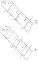
- Figure 1 shows a first embodiment of the construction according to the invention.
- Figure 2 shows a second embodiment of the construction according to the invention.
- Figure 3 shows a third embodiment of the construction according to the invention.
- Figure 4 shows a fourth embodiment of the construction according to the invention.
- Figure 5 shows a fifth embodiment of the construction according to the invention.
- Figure 6 shows a larger-scale view of the encircled detail VI of Figure 5.
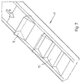
- Figure 7 shows a sixth embodiment of the construction according to the invention.
- Figure 1 diagrammatically illustrates a conveyor track or chute 1, which may form part of a conveyor and which may be arranged in such a manner thereby, that objects to be displaced can move downwards across the conveyor track 1 under the action of gravity, in the direction according to the arrow A.
- guide means may be provided at the side of the conveyor track or chute, so as to prevent the objects in question from falling sideways from the conveyor track 1.
- flaps 2 are provided regularly spaced from each other, when seen in the longitudinal direction of the conveyor track 1, said flaps being pivotable with respect to the other part of the conveyor track 1, about pivot pins 3 which, when seen in the direction of movement of the objects across the conveyor track in the direction according to the arrow A, are located at the downstream side of the flaps 2 and extend transversely to the longitudinal direction of the conveyor track.
- the flaps 2 are thereby pivotable between a first position, in which the upper sides of the flaps lie in one plane with the further part of the bearing surface 4 of the conveyor track 1, across which the objects move, and a second position, in which the flaps project above said bearing surface 4, as is drawn in Figure 1 for the centre one of the three flaps that are shown.
- the flaps 2 can be pivoted by suitable setting means, e.g. setting cylinders or the like.
- the flaps may thereby be controlled by means not shown, which e.g. detect the velocity of arriving objects and/or the pile-up of objects near the discharge end of the conveyor track.
- the pivotable flaps 2 are replaced by partitions or guide plates 5 extending transversely to the longitudinal direction of the conveyor track and being movable up and down in the direction according to the arrows B, which partitions or guide plates can be moved by means not shown, such as e.g. setting cylinders or the like, between a first position, in which the upper edge of the partition or guide plate 5 lies in one plane with the bearing surface 4 or slightly below said bearing surface, and a second position, in which the partition of guide plate 5 projects above the bearing surface 4, so as to stop an arriving object.
- partitions or guide plates 5 extending transversely to the longitudinal direction of the conveyor track and being movable up and down in the direction according to the arrows B, which partitions or guide plates can be moved by means not shown, such as e.g. setting cylinders or the like, between a first position, in which the upper edge of the partition or guide plate 5 lies in one plane with the bearing surface 4 or slightly below said bearing surface, and a second position, in which the partition of guide plate
- groups of adjacent pivotable flaps 6 and 7 are disposed at regular intervals in the longitudinal direction of the conveyor track 1.
- the flap 6, which is disposed upstream of the flap 7, when seen in the intended direction of movement of the objects according to the arrow A, is pivotable with respect to the other part of the conveyor track, about pivots 8 extending perpendicularly to the longitudinal direction of the conveyor track, said pivots being disposed at the upstream side of the flap 6.
- the flap 7 is similarly pivotable about pivots 9 extending parallel to the pivots 8, said pivots 9 being disposed at the downstream edge of the flap 7.
- the bearing surface of the conveyor track is formed by a flat belt 10 made of a flexible material, e.g. flexible plastic material, which rests on a flat bearing plate 11 forming part of the conveyor track.
- the load-bearing belt 10 may e.g. be fixed to the frame of the conveyor track, whilst near its bottom end means are provided that keep the load-bearing belt 10 tensioned in such a manner, that said belt tends to bed down smoothly on the flat bearing plate 11.
- the embodiment illustrated in Figures 5 and 6 includes a wavy bearing surface 13 of the conveyor track, with peaks and valleys extending in the longitudinal direction of the conveyor track.
- Strips 14, which are made of a flexible material and which extend in the longitudinal direction of the load-bearing belt 13, are placed in the valleys of said load-bearing belt. If desired said strips can be moved upwards by lifting means (not shown) at regularly spaced locations, so that the parts 14' and 14'' respectively project above the peaks of the bearing surface 13, so as to be able to slow down arriving objects in this manner.
- the bearing surface is formed by a number of flaps 15 disposed one behind the other, said flaps being pivotable with respect to the other part of the conveyor track, about pivot pins extending perpendicularly to the longitudinal direction of the conveyor track, said pivot pins being disposed near the downstream sides of the respective flaps 15.
- Each of said flaps may thereby be arranged in such a manner, that the upper boundary faces of said flaps lie in one plane, so that an object can move across the bearing surface formed by said flaps without impediment. From this position each flap may be pivoted upwards as desired, so as to slow down an object. It will be apparent that such a slowed-down object will then come to rest on a flap located downstream of the upwardly pivoted flap.
- the flap on which the object is present may be pivoted upwards again, so as to assist in setting the object on said flap in motion.
Landscapes
- Engineering & Computer Science (AREA)
- Mechanical Engineering (AREA)
- Discharge Of Articles From Conveyors (AREA)
- Braking Arrangements (AREA)
- Chutes (AREA)
- Handcart (AREA)
Applications Claiming Priority (2)
| Application Number | Priority Date | Filing Date | Title |
|---|---|---|---|
| NL9101171 | 1991-07-05 | ||
| NL9101171A NL9101171A (nl) | 1991-07-05 | 1991-07-05 | Transportinstallatie. |
Publications (2)
| Publication Number | Publication Date |
|---|---|
| EP0521541A1 true EP0521541A1 (fr) | 1993-01-07 |
| EP0521541B1 EP0521541B1 (fr) | 1995-08-09 |
Family
ID=19859470
Family Applications (1)
| Application Number | Title | Priority Date | Filing Date |
|---|---|---|---|
| EP92201370A Expired - Lifetime EP0521541B1 (fr) | 1991-07-05 | 1992-05-14 | Colonne de descente munie de moyens de retardement |
Country Status (4)
| Country | Link |
|---|---|
| EP (1) | EP0521541B1 (fr) |
| AT (1) | ATE126167T1 (fr) |
| DE (1) | DE69203985T2 (fr) |
| NL (1) | NL9101171A (fr) |
Cited By (11)
| Publication number | Priority date | Publication date | Assignee | Title |
|---|---|---|---|---|
| FR2707271A1 (fr) * | 1993-07-09 | 1995-01-13 | Mannesmann Ag | Dispositif pour le guidage réglé d'objets. |
| EP0860257A1 (fr) * | 1997-02-21 | 1998-08-26 | ELBA-WERK Maschinen-Gesellschaft mbH & Co. | Dispositif de mesure d'humidité de constituants de matériaux de construction en vrac |
| WO1998055379A1 (fr) * | 1997-06-04 | 1998-12-10 | Crisplant A/S | Transporteur et procede d'actionnement d'un transporteur |
| BE1011345A3 (nl) * | 1997-09-01 | 1999-07-06 | Egemin Nv | Inrichting voor het transport van voorwerpen. |
| EP1127812A1 (fr) * | 2000-02-23 | 2001-08-29 | PARSYS Produktionstechnik GmbH | Dispositif de transfert de marchandises en colis |
| WO2011076987A1 (fr) * | 2009-12-23 | 2011-06-30 | Itella Oyj | Goulotte de tri, procédé permettant de traiter un ou plusieurs articles de courrier et système à étages multiples |
| CN105174114A (zh) * | 2015-08-14 | 2015-12-23 | 中节能光伏农业科技(招远)有限公司 | 一种用于太阳能电池板的提升装置 |
| AU2011242137B2 (en) * | 2010-10-27 | 2016-06-09 | Metso Finland Oy | Material transfer |
| EP3248914B1 (fr) * | 2016-05-20 | 2020-02-26 | Deutsche Post AG | Glissière pour marchandise de détail et procédé d'utilisation d'une telle glissière |
| US20220396439A1 (en) * | 2021-06-11 | 2022-12-15 | AI International, Inc. | Systems and methods for sorting and dispensing packages |
| EP4319929A4 (fr) * | 2021-04-09 | 2025-02-26 | Dexterity, Inc. | Structure commandée par robot pour réguler un flux d'objets |
Citations (6)
| Publication number | Priority date | Publication date | Assignee | Title |
|---|---|---|---|---|
| GB839287A (en) * | 1958-07-08 | 1960-06-29 | Miag Muehlenbau & Ind Gmbh | Improvements in or relating to apparatus for the storage and loading of piece goods |
| DE1123975B (de) * | 1959-03-12 | 1962-02-15 | Heinr Auer Muehlenwerke Komman | Vorrichtung zur Regulierung der Lauf- und Beschleunigungsverhaeltnisse von auf geneigten Bahnen rutschendem Stueckgut |
| DE1135365B (de) * | 1959-12-15 | 1962-08-23 | Miag Muehlenbau & Ind Gmbh | Einrichtung zum Bremsen von Stueckgut auf Speicherrutschen |
| US4130193A (en) * | 1977-04-25 | 1978-12-19 | Bourgeois Ronald D | Transfer system for conveyor systems |
| US4274527A (en) * | 1977-09-27 | 1981-06-23 | Baker John H | Apparatus and method for uniformly spreading a flowing stream of dry solids |
| DE3500206A1 (de) * | 1985-01-05 | 1986-07-10 | Bültmann KG, 5982 Neuenrade | Abrollvorrichtung fuer rohre oder stangen |
-
1991
- 1991-07-05 NL NL9101171A patent/NL9101171A/nl not_active Application Discontinuation
-
1992
- 1992-05-14 AT AT92201370T patent/ATE126167T1/de not_active IP Right Cessation
- 1992-05-14 DE DE69203985T patent/DE69203985T2/de not_active Expired - Fee Related
- 1992-05-14 EP EP92201370A patent/EP0521541B1/fr not_active Expired - Lifetime
Patent Citations (6)
| Publication number | Priority date | Publication date | Assignee | Title |
|---|---|---|---|---|
| GB839287A (en) * | 1958-07-08 | 1960-06-29 | Miag Muehlenbau & Ind Gmbh | Improvements in or relating to apparatus for the storage and loading of piece goods |
| DE1123975B (de) * | 1959-03-12 | 1962-02-15 | Heinr Auer Muehlenwerke Komman | Vorrichtung zur Regulierung der Lauf- und Beschleunigungsverhaeltnisse von auf geneigten Bahnen rutschendem Stueckgut |
| DE1135365B (de) * | 1959-12-15 | 1962-08-23 | Miag Muehlenbau & Ind Gmbh | Einrichtung zum Bremsen von Stueckgut auf Speicherrutschen |
| US4130193A (en) * | 1977-04-25 | 1978-12-19 | Bourgeois Ronald D | Transfer system for conveyor systems |
| US4274527A (en) * | 1977-09-27 | 1981-06-23 | Baker John H | Apparatus and method for uniformly spreading a flowing stream of dry solids |
| DE3500206A1 (de) * | 1985-01-05 | 1986-07-10 | Bültmann KG, 5982 Neuenrade | Abrollvorrichtung fuer rohre oder stangen |
Non-Patent Citations (1)
| Title |
|---|
| PATENT ABSTRACTS OF JAPAN vol. 10, no. 18 (M-448)(2075) & JP-A-60 178 106 ( TOUYOU SEIMAIKI SEISAKUSHO ) * |
Cited By (14)
| Publication number | Priority date | Publication date | Assignee | Title |
|---|---|---|---|---|
| FR2707271A1 (fr) * | 1993-07-09 | 1995-01-13 | Mannesmann Ag | Dispositif pour le guidage réglé d'objets. |
| EP0860257A1 (fr) * | 1997-02-21 | 1998-08-26 | ELBA-WERK Maschinen-Gesellschaft mbH & Co. | Dispositif de mesure d'humidité de constituants de matériaux de construction en vrac |
| WO1998055379A1 (fr) * | 1997-06-04 | 1998-12-10 | Crisplant A/S | Transporteur et procede d'actionnement d'un transporteur |
| BE1011345A3 (nl) * | 1997-09-01 | 1999-07-06 | Egemin Nv | Inrichting voor het transport van voorwerpen. |
| EP1127812A1 (fr) * | 2000-02-23 | 2001-08-29 | PARSYS Produktionstechnik GmbH | Dispositif de transfert de marchandises en colis |
| WO2011076987A1 (fr) * | 2009-12-23 | 2011-06-30 | Itella Oyj | Goulotte de tri, procédé permettant de traiter un ou plusieurs articles de courrier et système à étages multiples |
| AU2011242137C1 (en) * | 2010-10-27 | 2016-10-27 | Metso Finland Oy | Material transfer |
| AU2011242137B2 (en) * | 2010-10-27 | 2016-06-09 | Metso Finland Oy | Material transfer |
| CN105174114A (zh) * | 2015-08-14 | 2015-12-23 | 中节能光伏农业科技(招远)有限公司 | 一种用于太阳能电池板的提升装置 |
| EP3248914B1 (fr) * | 2016-05-20 | 2020-02-26 | Deutsche Post AG | Glissière pour marchandise de détail et procédé d'utilisation d'une telle glissière |
| EP4319929A4 (fr) * | 2021-04-09 | 2025-02-26 | Dexterity, Inc. | Structure commandée par robot pour réguler un flux d'objets |
| US12486121B2 (en) | 2021-04-09 | 2025-12-02 | Dexterity, Inc. | Robotically-controlled structure to regulate item flow |
| US20220396439A1 (en) * | 2021-06-11 | 2022-12-15 | AI International, Inc. | Systems and methods for sorting and dispensing packages |
| US12098038B2 (en) * | 2021-06-11 | 2024-09-24 | AI International, Inc. | Systems and methods for sorting and dispensing packages |
Also Published As
| Publication number | Publication date |
|---|---|
| EP0521541B1 (fr) | 1995-08-09 |
| NL9101171A (nl) | 1993-02-01 |
| DE69203985D1 (de) | 1995-09-14 |
| ATE126167T1 (de) | 1995-08-15 |
| DE69203985T2 (de) | 1995-11-30 |
Similar Documents
| Publication | Publication Date | Title |
|---|---|---|
| US5638938A (en) | Apparatus and method for handling flow of packages | |
| US9969554B2 (en) | Chute for articles and method for using such a chute | |
| EP0521541A1 (fr) | Colonne de descente munie de moyens de retardement | |
| US9126758B2 (en) | Arrangements for transferring articles | |
| US5850902A (en) | Transferring articles from a moving belt edge onto a normally disposed moving conveyor belt | |
| US20240425300A1 (en) | Cross-belt sorter | |
| US3286811A (en) | Selective delivery tilting slat conveyor for mail bag handling systems | |
| US5979633A (en) | Conveyor having high speed discharge capabilities | |
| EP3693301B1 (fr) | Convoyeur avec poussoirs | |
| US8245835B2 (en) | Sorting apparatus | |
| EP0742165A1 (fr) | Dispositif pour trier des produits | |
| CA1085885A (fr) | Methode de disperiosn de billes de bois et machine pour mettre la methode en application | |
| US5722532A (en) | Convergent/divergent product conveyor | |
| EP0315807A1 (fr) | Procédé et dispositif pour l'empilage d'articles et l'alimentation des piles à un emplacement de décharge | |
| US3913730A (en) | Article transferring apparatus | |
| US5562281A (en) | Leading end stacked position regulating apparatus in thin sheet material stacker | |
| US3918572A (en) | Lateral discharge chute and gate apparatus | |
| US10370196B2 (en) | Food product separating and aligning apparatus | |
| EP0009014A1 (fr) | Dispositif de transport de feuilles en matériau magnétique | |
| US4867298A (en) | Conveyor system for planar panel | |
| EP3798161A1 (fr) | Appareil pour le transport et l'évacuation contrôlée de produits | |
| KR102853804B1 (ko) | 방향전환부를 포함하는 물품 이송장치 | |
| JP3054037B2 (ja) | 作物計量選別装置 | |
| US3991866A (en) | Discharge chute structure | |
| JPH057378U (ja) | 作物選別装置 |
Legal Events
| Date | Code | Title | Description |
|---|---|---|---|
| PUAI | Public reference made under article 153(3) epc to a published international application that has entered the european phase |
Free format text: ORIGINAL CODE: 0009012 |
|
| AK | Designated contracting states |
Kind code of ref document: A1 Designated state(s): AT BE CH DE DK ES FR GB GR IT LI LU MC NL PT SE |
|
| 17P | Request for examination filed |
Effective date: 19921203 |
|
| 17Q | First examination report despatched |
Effective date: 19940406 |
|
| GRAA | (expected) grant |
Free format text: ORIGINAL CODE: 0009210 |
|
| AK | Designated contracting states |
Kind code of ref document: B1 Designated state(s): AT BE CH DE DK ES FR GB GR IT LI LU MC NL PT SE |
|
| PG25 | Lapsed in a contracting state [announced via postgrant information from national office to epo] |
Ref country code: IT Free format text: LAPSE BECAUSE OF FAILURE TO SUBMIT A TRANSLATION OF THE DESCRIPTION OR TO PAY THE FEE WITHIN THE PRESCRIBED TIME-LIMIT;WARNING: LAPSES OF ITALIAN PATENTS WITH EFFECTIVE DATE BEFORE 2007 MAY HAVE OCCURRED AT ANY TIME BEFORE 2007. THE CORRECT EFFECTIVE DATE MAY BE DIFFERENT FROM THE ONE RECORDED. Effective date: 19950809 Ref country code: LI Effective date: 19950809 Ref country code: ES Free format text: THE PATENT HAS BEEN ANNULLED BY A DECISION OF A NATIONAL AUTHORITY Effective date: 19950809 Ref country code: DK Effective date: 19950809 Ref country code: MC Free format text: LAPSE BECAUSE OF NON-PAYMENT OF DUE FEES Effective date: 19950809 Ref country code: GR Free format text: LAPSE BECAUSE OF FAILURE TO SUBMIT A TRANSLATION OF THE DESCRIPTION OR TO PAY THE FEE WITHIN THE PRESCRIBED TIME-LIMIT Effective date: 19950809 Ref country code: FR Free format text: THE PATENT HAS BEEN ANNULLED BY A DECISION OF A NATIONAL AUTHORITY Effective date: 19950809 Ref country code: BE Effective date: 19950809 Ref country code: AT Effective date: 19950809 Ref country code: CH Effective date: 19950809 |
|
| REF | Corresponds to: |
Ref document number: 126167 Country of ref document: AT Date of ref document: 19950815 Kind code of ref document: T |
|
| REF | Corresponds to: |
Ref document number: 69203985 Country of ref document: DE Date of ref document: 19950914 |
|
| PG25 | Lapsed in a contracting state [announced via postgrant information from national office to epo] |
Ref country code: SE Effective date: 19951109 Ref country code: PT Effective date: 19951109 |
|
| EN | Fr: translation not filed | ||
| PG25 | Lapsed in a contracting state [announced via postgrant information from national office to epo] |
Ref country code: GB Effective date: 19960514 |
|
| PG25 | Lapsed in a contracting state [announced via postgrant information from national office to epo] |
Ref country code: LU Free format text: LAPSE BECAUSE OF NON-PAYMENT OF DUE FEES Effective date: 19960531 |
|
| PLBE | No opposition filed within time limit |
Free format text: ORIGINAL CODE: 0009261 |
|
| STAA | Information on the status of an ep patent application or granted ep patent |
Free format text: STATUS: NO OPPOSITION FILED WITHIN TIME LIMIT |
|
| 26N | No opposition filed | ||
| GBPC | Gb: european patent ceased through non-payment of renewal fee |
Effective date: 19960514 |
|
| PGFP | Annual fee paid to national office [announced via postgrant information from national office to epo] |
Ref country code: DE Payment date: 20080523 Year of fee payment: 17 |
|
| PGFP | Annual fee paid to national office [announced via postgrant information from national office to epo] |
Ref country code: NL Payment date: 20080531 Year of fee payment: 17 |
|
| NLV4 | Nl: lapsed or anulled due to non-payment of the annual fee |
Effective date: 20091201 |
|
| PG25 | Lapsed in a contracting state [announced via postgrant information from national office to epo] |
Ref country code: NL Free format text: LAPSE BECAUSE OF NON-PAYMENT OF DUE FEES Effective date: 20091201 |
|
| PG25 | Lapsed in a contracting state [announced via postgrant information from national office to epo] |
Ref country code: DE Free format text: LAPSE BECAUSE OF NON-PAYMENT OF DUE FEES Effective date: 20091201 |