EP1128073A1 - Procédé de fermeture de l'extrémité formant le fond ou le guide de tige du fût d'un cylindre de travail - Google Patents
Procédé de fermeture de l'extrémité formant le fond ou le guide de tige du fût d'un cylindre de travail Download PDFInfo
- Publication number
- EP1128073A1 EP1128073A1 EP00440059A EP00440059A EP1128073A1 EP 1128073 A1 EP1128073 A1 EP 1128073A1 EP 00440059 A EP00440059 A EP 00440059A EP 00440059 A EP00440059 A EP 00440059A EP 1128073 A1 EP1128073 A1 EP 1128073A1
- Authority
- EP
- European Patent Office
- Prior art keywords
- barrel
- flange
- closing
- cylinder
- groove
- Prior art date
- Legal status (The legal status is an assumption and is not a legal conclusion. Google has not performed a legal analysis and makes no representation as to the accuracy of the status listed.)
- Withdrawn
Links
- 238000000034 method Methods 0.000 title claims description 11
- 238000002788 crimping Methods 0.000 claims description 6
- 239000000463 material Substances 0.000 claims description 3
- 238000012423 maintenance Methods 0.000 claims description 2
- 239000012530 fluid Substances 0.000 abstract description 8
- 238000007789 sealing Methods 0.000 abstract description 2
- 238000004026 adhesive bonding Methods 0.000 description 2
- 238000011144 upstream manufacturing Methods 0.000 description 2
- 238000003466 welding Methods 0.000 description 2
- 230000007423 decrease Effects 0.000 description 1
- 230000005489 elastic deformation Effects 0.000 description 1
- 238000005304 joining Methods 0.000 description 1
- 238000004519 manufacturing process Methods 0.000 description 1
- 239000002184 metal Substances 0.000 description 1
- 238000012986 modification Methods 0.000 description 1
- 230000004048 modification Effects 0.000 description 1
- 230000002093 peripheral effect Effects 0.000 description 1
- 230000001256 tonic effect Effects 0.000 description 1
Images
Classifications
-
- F—MECHANICAL ENGINEERING; LIGHTING; HEATING; WEAPONS; BLASTING
- F15—FLUID-PRESSURE ACTUATORS; HYDRAULICS OR PNEUMATICS IN GENERAL
- F15B—SYSTEMS ACTING BY MEANS OF FLUIDS IN GENERAL; FLUID-PRESSURE ACTUATORS, e.g. SERVOMOTORS; DETAILS OF FLUID-PRESSURE SYSTEMS, NOT OTHERWISE PROVIDED FOR
- F15B15/00—Fluid-actuated devices for displacing a member from one position to another; Gearing associated therewith
- F15B15/08—Characterised by the construction of the motor unit
- F15B15/14—Characterised by the construction of the motor unit of the straight-cylinder type
- F15B15/1423—Component parts; Constructional details
- F15B15/1438—Cylinder to end cap assemblies
-
- F—MECHANICAL ENGINEERING; LIGHTING; HEATING; WEAPONS; BLASTING
- F15—FLUID-PRESSURE ACTUATORS; HYDRAULICS OR PNEUMATICS IN GENERAL
- F15B—SYSTEMS ACTING BY MEANS OF FLUIDS IN GENERAL; FLUID-PRESSURE ACTUATORS, e.g. SERVOMOTORS; DETAILS OF FLUID-PRESSURE SYSTEMS, NOT OTHERWISE PROVIDED FOR
- F15B15/00—Fluid-actuated devices for displacing a member from one position to another; Gearing associated therewith
- F15B15/08—Characterised by the construction of the motor unit
- F15B15/14—Characterised by the construction of the motor unit of the straight-cylinder type
- F15B15/149—Fluid interconnections, e.g. fluid connectors, passages
Definitions
- the subject of the present invention is a method of securing of a closure flange at the end forming the bottom or the rod guide of the barrel of a jack and including a hydraulic cylinder.
- Current hydraulic cylinders are made up of a closed cylinder or barrel-shaped barrel of sealingly at each of its ends by a flange and containing an axially movable piston whose rod is guided by a guide bore in one either of the two body closing flanges cylindrical.
- the flanges are generally secured to the barrel ends by screwing, gluing, welding, by rod, or by tie rods and usually have a channel for conveying the pressurized fluid into the chamber corresponding cylinder, when this channel is not welded directly on the cylindrical body.
- the document US 5 680 808 relates to a jack comprising a cylinder body whose flanges closing its ends are adjustable in rotation about the axis of said body, which body has at each of its ends, on its internal face, an annular groove while each flange is fitted with a compressible annular ring coming from forcefully insert into said annular groove to block axially said flange in the closed position while allowing an axial rotation of the latter.
- this device has the disadvantage to use a stop segment whose operations of fastening in the external surface of the flange, as well as the realization of the annular groove practiced in the body of cylinder to receive said insert increase the manufacturing cost of the cylinder.
- the object of the present invention is to remedy these disadvantages by proposing a joining process a closing flange at the end of the cylinder barrel allowing to rotate the said flange to adjust the angular position of the fluid inlets, at a cost lower than current fastening systems, and allowing keep the closing flange in rotation with a sufficient resisting torque to avoid a free rotation.
- the method of fixing a closing flange at the end of the barrel of a cylinder consists insert the flange into the end of the cylinder barrel and then carry out a controlled crimping of the barrel by a deformation of its material, forming a constriction, which is pushed back into a throat of the flange so on the one hand to ensure mechanically the tear resistance of the latter from was and on the other hand to create a resistant couple between said flange and said barrel to allow axial rotation of the flange and its maintenance in angular position.
- the tearing of the flange, whose resistance said removal is ensured by the crimping process according to the present invention is caused by the pressure at inside the barrel or by an external tensile force when the cylinder rod is fully extended if the piston abuts on the rod guide.
- the flange throat has a section transverse in V.
- the groove has a cross section rounded.
- control of the constriction forming the deformation of material in the barrel can be made by means of a stop or by stopping the crimping pressure when this exceeds a threshold value.
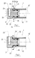
- a cylinder 1 consisting of a barrel 10 closed at one of its ends by a flange 2 forming a plug for its closure.
- the flange 2 has a cylindrical shape, but can have any other shape, and has a head 20 which abuts against the end of the barrel 10 and which extends by a part 21 of diameter substantially equal to internal diameter of the barrel 10 so as to be inserted closely into the latter.
- a peripheral groove 22 of V-shaped cross section east practiced in part 21 of the flange 2 near this last and that a channel 23 is practiced in the flange 2 for convey a pressurized fluid into chamber 11 of the barrel 10.
- the attachment of the flange 2 to the end of the barrel 10 of working cylinder 1 is produced according to the process of the invention by carrying out in a controlled manner, according to R, a constriction 24 of the barrel wall 10 facing the groove 22 corresponding to an elastic deformation of the metal of the barrel which is pushed back into the groove 24 so as to ensure mechanically the resistance to tearing, which shrinks 24 is positioned in the latter in contact with its two upstream 25 and downstream 26 walls.
- the user can, depending on the application, change the orientation of the 23 'entrance of the fluid inlet channel 23 by rotating the flange 2, relative to the cylinder 10 of the cylinder 1, around its virtual axis 10 ', which flange 2, due to the resistant torque, is maintained in this angular position.
- the flange 2 can also form the bottom of cylinder 1 as the other end forming the guide cylinder rod 1.
- the groove 22 ′ may be of rounded shape.
- the crimping method according to the invention allows, without adding additional room, and in a very small footprint to create a mechanical stress of friction between the barrel and the closing flange.
- the sealing function is achieved by a tonic seal, by example, positioned in a groove in the flange closing.
Landscapes
- Engineering & Computer Science (AREA)
- Physics & Mathematics (AREA)
- Fluid Mechanics (AREA)
- Mechanical Engineering (AREA)
- General Engineering & Computer Science (AREA)
- Pressure Vessels And Lids Thereof (AREA)
Abstract
Description
- la figure 1 représente une vue en coupe d'un premier mode de réalisation préférentiel du dispositif de fermeture selon l'invention.
- la figure 2 représente une vue en coupe d'un deuxième mode de réalisation du dispositif de fermeture selon l'invention.
Claims (4)
- Procédé de fixation d'un flasque (2) de fermeture à l'extrémité du fût (10) d'un vérin (1) selon l'invention caractérisé en ce qu'il consiste à insérer le flasque (2) dans l'extrémité du fût (10) du vérin (1) puis à effectuer un sertissage contrôlé dudit fût (10) par une déformation de sa matière, formant un rétreint, qui est refoulée dans une gorge (24) du flasque (2) de manière à assurer mécaniquement d'une part la résistance à l'arrachement et d'autre part à créer un couple résistant entre ledit flasque (2) et ledit fût (10) pour autoriser la rotation axiale de ce dernier et son maintien en position angulaire.
- Procédé selon la revendication 1 caractérisé en ce que la gorge (22) présente une section transversale en V.
- Procédé selon la revendication 1 caractérisé en ce que la gorge (22') présente une section transversale arrondie.
- Procédé selon l'une quelconque des revendications précédentes caractérisé en ce que le contrôle de la réalisation du rétreint (24;24') est effectué au moyen d'une butée ou par arrêt de la pression de sertissage de l'extrémité du fût (10) lorsque celle-ci dépasse une valeur seuil.
Priority Applications (1)
| Application Number | Priority Date | Filing Date | Title |
|---|---|---|---|
| EP00440059A EP1128073A1 (fr) | 2000-02-28 | 2000-02-28 | Procédé de fermeture de l'extrémité formant le fond ou le guide de tige du fût d'un cylindre de travail |
Applications Claiming Priority (1)
| Application Number | Priority Date | Filing Date | Title |
|---|---|---|---|
| EP00440059A EP1128073A1 (fr) | 2000-02-28 | 2000-02-28 | Procédé de fermeture de l'extrémité formant le fond ou le guide de tige du fût d'un cylindre de travail |
Publications (1)
| Publication Number | Publication Date |
|---|---|
| EP1128073A1 true EP1128073A1 (fr) | 2001-08-29 |
Family
ID=8174104
Family Applications (1)
| Application Number | Title | Priority Date | Filing Date |
|---|---|---|---|
| EP00440059A Withdrawn EP1128073A1 (fr) | 2000-02-28 | 2000-02-28 | Procédé de fermeture de l'extrémité formant le fond ou le guide de tige du fût d'un cylindre de travail |
Country Status (1)
| Country | Link |
|---|---|
| EP (1) | EP1128073A1 (fr) |
Cited By (5)
| Publication number | Priority date | Publication date | Assignee | Title |
|---|---|---|---|---|
| WO2004003393A1 (fr) * | 2002-06-27 | 2004-01-08 | Hydac Technology Gmbh | Dispositif pour la technique fluidique, par exemple cylindre de travail et accumulateur, en particulier un accumulateur hydraulique |
| WO2004067968A1 (fr) * | 2003-02-01 | 2004-08-12 | Hydac Technology Gmbh | Procede de realisation d'accumulateurs hydrauliques |
| JP2013234693A (ja) * | 2012-05-07 | 2013-11-21 | Daishin Shoko:Kk | 油圧シリンダ及び油圧シリンダ装置 |
| EP3647624A1 (fr) * | 2018-10-29 | 2020-05-06 | STABILUS GmbH | Actionneur |
| DE102013217841B4 (de) * | 2013-09-06 | 2021-05-20 | Aventics Gmbh | Zylinder, aufweisend ein Zylinderrohr und ein Abschlusselement und Verfahren zum Herstellen eines Zylinders |
Citations (4)
| Publication number | Priority date | Publication date | Assignee | Title |
|---|---|---|---|---|
| FR1347058A (fr) * | 1962-10-17 | 1963-12-27 | Continental Oil Co | Moteur hydraulique convenant en particulier aux dispositifs d'exploration sismique |
| EP0588779A1 (fr) * | 1992-09-02 | 1994-03-23 | Hoerbiger Ventilwerke Aktiengesellschaft | Vérin hydraulique |
| US5680808A (en) | 1996-05-09 | 1997-10-28 | Ingersoll-Rand Company | Fluid cylinder and method of assembly |
| EP0841488A2 (fr) * | 1996-11-08 | 1998-05-13 | HOERBIGER GmbH | Vérin de travail |
-
2000
- 2000-02-28 EP EP00440059A patent/EP1128073A1/fr not_active Withdrawn
Patent Citations (4)
| Publication number | Priority date | Publication date | Assignee | Title |
|---|---|---|---|---|
| FR1347058A (fr) * | 1962-10-17 | 1963-12-27 | Continental Oil Co | Moteur hydraulique convenant en particulier aux dispositifs d'exploration sismique |
| EP0588779A1 (fr) * | 1992-09-02 | 1994-03-23 | Hoerbiger Ventilwerke Aktiengesellschaft | Vérin hydraulique |
| US5680808A (en) | 1996-05-09 | 1997-10-28 | Ingersoll-Rand Company | Fluid cylinder and method of assembly |
| EP0841488A2 (fr) * | 1996-11-08 | 1998-05-13 | HOERBIGER GmbH | Vérin de travail |
Cited By (8)
| Publication number | Priority date | Publication date | Assignee | Title |
|---|---|---|---|---|
| WO2004003393A1 (fr) * | 2002-06-27 | 2004-01-08 | Hydac Technology Gmbh | Dispositif pour la technique fluidique, par exemple cylindre de travail et accumulateur, en particulier un accumulateur hydraulique |
| DE10228700B3 (de) * | 2002-06-27 | 2004-02-12 | Hydac Technology Gmbh | Fluidtechnische Vorrichtung wie Arbeitszylinder und Speicher, insbesondere Hydrospeicher |
| WO2004067968A1 (fr) * | 2003-02-01 | 2004-08-12 | Hydac Technology Gmbh | Procede de realisation d'accumulateurs hydrauliques |
| EP1808605A1 (fr) * | 2003-02-01 | 2007-07-18 | HYDAC Technology GmbH | Procédé de fabrication d'accumulateurs de pistons |
| US8387253B2 (en) | 2003-02-01 | 2013-03-05 | Hydac Technology Gmbh | Method for the production of piston-type accumulators |
| JP2013234693A (ja) * | 2012-05-07 | 2013-11-21 | Daishin Shoko:Kk | 油圧シリンダ及び油圧シリンダ装置 |
| DE102013217841B4 (de) * | 2013-09-06 | 2021-05-20 | Aventics Gmbh | Zylinder, aufweisend ein Zylinderrohr und ein Abschlusselement und Verfahren zum Herstellen eines Zylinders |
| EP3647624A1 (fr) * | 2018-10-29 | 2020-05-06 | STABILUS GmbH | Actionneur |
Similar Documents
| Publication | Publication Date | Title |
|---|---|---|
| EP0777049B1 (fr) | Dispositif de raccordement de pompe | |
| FR2489896A1 (fr) | Dispositif d'entrainement, notamment pour le tendeur de rappel d'un systeme de ceinture de securite | |
| EP1106212B1 (fr) | Lance à incendie | |
| FR2463351A1 (fr) | Dispositif amortisseur pour soupapes de non-retour | |
| FR2616862A1 (fr) | Dispositif d'accouplement debrayable a serrage hydraulique | |
| FR2511744A1 (fr) | Soupape de regulation de debit de fluide transmis a un verin | |
| EP0874761A1 (fr) | Embout de distribution de produits liquides ou pateux | |
| FR2795137A1 (fr) | Clapet notamment clapet anti-retour de pompe a haute pression | |
| EP1128073A1 (fr) | Procédé de fermeture de l'extrémité formant le fond ou le guide de tige du fût d'un cylindre de travail | |
| FR2663715A1 (fr) | Dispositif de neutralisation d'une soupape de pression residuelle d'une bouteille a gaz. | |
| EP0134726A1 (fr) | Valve de décharge brutale commandée par un piston | |
| CH390644A (fr) | Robinet | |
| FR2856485A1 (fr) | Soupape de surpression | |
| FR3025279A1 (fr) | Connecteur de valve pour une valve d'un dispositif de gonflage, et adaptateur comportant celui-ci | |
| FR2755736A1 (fr) | Dispositif de debrayage hydraulique a piston annulaire muni d'un joint | |
| EP3215732A1 (fr) | Dispositif anti rotation d'une lance a carburant | |
| FR2757234A1 (fr) | Maitre-cylindre pour embrayage a friction ou frein hydraulique de vehicule | |
| FR2624245A1 (fr) | Soupape d'etranglement; comprenant un carter de soupape reduit et presentant des groupes supplementaires de canaux d'etranglement radiaux | |
| FR2790298A1 (fr) | Dispositif de fermeture de l'extremite formant le fond ou le guide de tige du fut d'un cylindre de travail | |
| FR3037377A1 (fr) | Regulateur de pression dynamique | |
| FR2655101A1 (fr) | Dispositif de solidarisation d'arbre par emboitement. | |
| EP3524860B1 (fr) | Organe de pilotage | |
| EP0490725B1 (fr) | Dispositif d'obturation d'un passage tubulaire de cable | |
| FR2552514A1 (fr) | Amortisseur du type fluidique | |
| FR2812263A1 (fr) | Dispositif de direction du type a cremaillere et pignon |
Legal Events
| Date | Code | Title | Description |
|---|---|---|---|
| PUAI | Public reference made under article 153(3) epc to a published international application that has entered the european phase |
Free format text: ORIGINAL CODE: 0009012 |
|
| AK | Designated contracting states |
Kind code of ref document: A1 Designated state(s): AT BE CH CY DE DK ES FI FR GB GR IE IT LI LU MC NL PT SE |
|
| AX | Request for extension of the european patent |
Free format text: AL;LT;LV;MK;RO;SI |
|
| AKX | Designation fees paid | ||
| REG | Reference to a national code |
Ref country code: DE Ref legal event code: 8566 |
|
| 17P | Request for examination filed |
Effective date: 20020528 |
|
| RBV | Designated contracting states (corrected) |
Designated state(s): AT BE CH CY DE DK ES FI FR GB GR IE IT LI LU MC NL PT SE |
|
| 17Q | First examination report despatched |
Effective date: 20031210 |
|
| STAA | Information on the status of an ep patent application or granted ep patent |
Free format text: STATUS: THE APPLICATION IS DEEMED TO BE WITHDRAWN |
|
| 18D | Application deemed to be withdrawn |
Effective date: 20040901 |