EP1128085A2 - Support de base de ressort - Google Patents
Support de base de ressort Download PDFInfo
- Publication number
- EP1128085A2 EP1128085A2 EP01102132A EP01102132A EP1128085A2 EP 1128085 A2 EP1128085 A2 EP 1128085A2 EP 01102132 A EP01102132 A EP 01102132A EP 01102132 A EP01102132 A EP 01102132A EP 1128085 A2 EP1128085 A2 EP 1128085A2
- Authority
- EP
- European Patent Office
- Prior art keywords
- spring
- section
- base element
- intermediate plate
- plate
- Prior art date
- Legal status (The legal status is an assumption and is not a legal conclusion. Google has not performed a legal analysis and makes no representation as to the accuracy of the status listed.)
- Granted
Links
- 239000002184 metal Substances 0.000 claims abstract description 14
- 229910052751 metal Inorganic materials 0.000 claims abstract description 14
- 238000004804 winding Methods 0.000 claims description 24
- 229920001971 elastomer Polymers 0.000 claims description 17
- 239000000463 material Substances 0.000 claims description 14
- 239000000806 elastomer Substances 0.000 claims description 12
- 230000008878 coupling Effects 0.000 claims description 2
- 238000010168 coupling process Methods 0.000 claims description 2
- 238000005859 coupling reaction Methods 0.000 claims description 2
- 230000006835 compression Effects 0.000 description 5
- 238000007906 compression Methods 0.000 description 5
- 210000003746 feather Anatomy 0.000 description 5
- 239000010405 anode material Substances 0.000 description 3
- 239000007787 solid Substances 0.000 description 3
- 239000000725 suspension Substances 0.000 description 3
- 229910000831 Steel Inorganic materials 0.000 description 2
- 238000010276 construction Methods 0.000 description 2
- 230000007797 corrosion Effects 0.000 description 2
- 238000005260 corrosion Methods 0.000 description 2
- 238000004519 manufacturing process Methods 0.000 description 2
- 230000000750 progressive effect Effects 0.000 description 2
- 238000005096 rolling process Methods 0.000 description 2
- 239000010959 steel Substances 0.000 description 2
- 230000001629 suppression Effects 0.000 description 2
- FGRBYDKOBBBPOI-UHFFFAOYSA-N 10,10-dioxo-2-[4-(N-phenylanilino)phenyl]thioxanthen-9-one Chemical compound O=C1c2ccccc2S(=O)(=O)c2ccc(cc12)-c1ccc(cc1)N(c1ccccc1)c1ccccc1 FGRBYDKOBBBPOI-UHFFFAOYSA-N 0.000 description 1
- 229910001335 Galvanized steel Inorganic materials 0.000 description 1
- HCHKCACWOHOZIP-UHFFFAOYSA-N Zinc Chemical compound [Zn] HCHKCACWOHOZIP-UHFFFAOYSA-N 0.000 description 1
- 229910001297 Zn alloy Inorganic materials 0.000 description 1
- 238000004026 adhesive bonding Methods 0.000 description 1
- 230000000712 assembly Effects 0.000 description 1
- 238000000429 assembly Methods 0.000 description 1
- 230000015572 biosynthetic process Effects 0.000 description 1
- 230000007423 decrease Effects 0.000 description 1
- 230000000994 depressogenic effect Effects 0.000 description 1
- 230000000694 effects Effects 0.000 description 1
- 230000005284 excitation Effects 0.000 description 1
- 239000008397 galvanized steel Substances 0.000 description 1
- 230000002093 peripheral effect Effects 0.000 description 1
- 239000004033 plastic Substances 0.000 description 1
- 230000002787 reinforcement Effects 0.000 description 1
- 230000003014 reinforcing effect Effects 0.000 description 1
- 125000006850 spacer group Chemical group 0.000 description 1
- 229910052725 zinc Inorganic materials 0.000 description 1
- 239000011701 zinc Substances 0.000 description 1
Images


Classifications
-
- F—MECHANICAL ENGINEERING; LIGHTING; HEATING; WEAPONS; BLASTING
- F16—ENGINEERING ELEMENTS AND UNITS; GENERAL MEASURES FOR PRODUCING AND MAINTAINING EFFECTIVE FUNCTIONING OF MACHINES OR INSTALLATIONS; THERMAL INSULATION IN GENERAL
- F16F—SPRINGS; SHOCK-ABSORBERS; MEANS FOR DAMPING VIBRATION
- F16F1/00—Springs
- F16F1/02—Springs made of steel or other material having low internal friction; Wound, torsion, leaf, cup, ring or the like springs, the material of the spring not being relevant
- F16F1/04—Wound springs
- F16F1/12—Attachments or mountings
- F16F1/126—Attachments or mountings comprising an element between the end coil of the spring and the support proper, e.g. an elastomeric annulus
Definitions
- the invention relates to a spring pad for arrangement between a spring plate and a helical spring.
- Such spring pads are used, for example, in vehicle construction Spring damper assemblies used for suspension of the vehicle wheels. However, it is Use not limited to vehicle construction. Rather, feather pads Use wherever helical springs are supported against a spring plate Need to become.
- the spring plate can be used separately with the spring Be part, but also integral with a wall portion of a larger unit, for. B. the vehicle body against which the spring is supported.
- Spring pads made of elastomer material are generally known from the prior art.
- DE 196 32 184 A1 discloses an elastic pad made of several layers of a film material is produced. This will be between the last one Coil of a spring and the associated spring plate arranged.
- Another, Spring support consisting exclusively of elastomer material is from DE 196 09 250 A1 known as a ring-like disc for supporting a barrel-shaped coil spring is trained.
- a spring strut is known from DE 42 11 176 C2, in which the spring support against a spring plate via a solid rubber ring.
- a spacer made of metal arranged its thickness increases from one side to the other, so that the solid rubber ring against the Spring plate is supported at an angle. This allows a uniform elasticity of the Achieve spring support, which counteracts bulging. The constructive However, the effort is considerable.
- EP 0 924 445 A2 discloses a metal reinforcement element in embed a rubber body so that it is enclosed by the rubber. For Simplification of production is proposed in EP 0 924 445 A2 instead of Reinforcing element made of metal to use one made of plastic.
- a support could directly against the usually metallic spring plate in Be considered.
- the direct contact between a metal spring and a metallic spring plate is however under dynamic loading of the spring like it occurs, for example, in a wheel suspension when operating a motor vehicle in which Usually associated with unpleasant squeaking and creaking noises.
- the invention has for its object a noise-free under load To create spring pad or spring arrangement.
- a spring pad for arrangement between a spring plate and a helical spring comprising a Base element made of an elastomer material for support against the spring plate, and an intermediate plate, preferably made of metal, on the side facing the spring of the Arranged base element, wherein the intermediate plate has a contact section, against the winding sections of the spring to the system, at least in the event of greater compression come, and the contact section has openings through which the Extend projections provided through the base element, which protrude into the contact section Protrude towards the spring.
- the intermediate plate which is preferably made of metal, also results in a certain broadening of the application of force into the elastomer material Base element. Depending on the thickness of the metal plate, a softer one may be used Elastomer or a thinner base element can be used.
- the intermediate plate is preferably made from a sacrificial anode material, for example zinc, manufactured and then serves to protect the spring from corrosion.
- the contact section is annular educated. Furthermore, the openings in the intermediate plate are directed radially Longitudinal slots are provided on the annular contact section.
- the annular coil springs used can be used independently of Deflection state to achieve a good suppression of noise.
- the projections are preferably each of the circumferential shape associated opening designed accordingly.
- the openings restrict the deformation space of the projections when compressed. This results in a certain structural stiffening effect in the area of the projections, which is something are harder than a freely deformable section of the same material on the base element. Even when using a relatively soft elastomer, it can be a good one Suppression of noise can be guaranteed.
- the intermediate plate is preferably attached to the base element by Vulcanizing or gluing.
- the protrusion by which the projections protrude beyond the contact section is preferably 0.75 to 1.25 mm. In this area it can be ensured that the Winding sections of the spring ultimately bear against the stiffer intermediate plate come to achieve a good introduction of force into the base element, on the other hand the formation of squeaking and creaking noises is particularly reliably prevented.
- the intermediate plate as Ring disc is formed, the thickness of about 5 to 10 percent of the thickness of a underlying flange portion of the base member.
- the washer can be also easy to manufacture from sheet metal.
- the Invention on the base element an annular centering section for radial contact provided against an outgoing turn section at the end of the spring.
- the Centering section is formed, for example, in one piece with the base element. He can but also as a separate component or section of the spring plate in the direction of the spring protruding to be coupled to the base element.
- a recess Picking up and supporting an outgoing turn section at the end of the spring intended For the use of coil springs with non-flattened ends, another advantageous embodiment of the invention on the base element a recess Picking up and supporting an outgoing turn section at the end of the spring intended.
- the helical spring is initially soft and without in the normal state Interposition of a metal part supported against the spring plate. With a larger one Resilience then reach further turn sections against the intermediate plate Investment. This allows, above all, a progressive spring characteristic with simple Realize means.
- the intermediate plate with the contact section extends to the annular centering section, with a spring end against the in the installed state Intermediate plate comes to rest.
- a recess adapted to the spring end on the Base element is then not required. Its shape therefore remains simple and for different springs can be used.
- a spring arrangement comprising a helical spring, which is arranged between two spring plates, wherein at least between one of the spring plates and the spring a spring pad of the is arranged as described above.
- the helical spring is barrel-shaped and with smaller coil diameters at the ends of the spring educated.
- Outgoing turn sections at the ends of the spring are each in one Recess supported on the base elements of the spring pads, however, come Winding sections with a larger winding diameter, at least with a larger one Deflection against the respective contact section of the intermediate plate and there located projections of the base element to the system.
- a spring arrangement is shown, for example, in a wheel or Axle suspension of a motor vehicle can be installed. It will be there between two Spring plates, which are not shown in Figure 10, held, an upper Spring plate on the body side and a lower spring plate on the wheel side.
- the upper Spring plate can be integrally formed with part of the vehicle body.
- the spring arrangement shown comprises a coil spring 1, which is between two Spring pads 2 and 3 are incorporated and can be supported against the spring plate.
- the coil spring 1 here is a steel spring with a barrel-shaped outer contour Application whose winding diameter decreases towards the axial ends of the spring.
- the spring ends 4 and 5 are not created here and are shaped accordingly Recesses on the spring pads 2 and 3 added.
- a conventional cylinder coil spring to use.
- the spring ends can also be placed on the last turn and, if necessary, be ground flat so that the ends of the spring are flat against the spring pads.
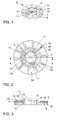
- the spring pads 2 and 3 shown in FIG. 10 are the first exemplary embodiment in FIG Figures 1 to 4 and as a second embodiment in Figures 5 to 7 in detail shown and are explained in more detail below.
- FIGS. 1 to 4 show the upper spring base 2 from FIG. 10
- Spring pad 2 comprises an annular base element 6 made of an elastomer material and an intermediate plate 7 made of metal, e.g. Steel on the side facing the spring 1 is arranged.
- the base element 6 is designed as a substantially flat disc and has an annular flange portion 8, which is radially centered around a arranged centering section 9 extends.
- the annular flange section 8 has one essentially constant thickness. From this, the centering section 9 lifts in the direction the spring 1. It is mainly used for the radial definition of the last turns of the spring 1 on the spring pad 2 and has several, preferably three, on its outer edge 10 claw-like projections 11 which hook with a winding section of the spring 1 or latch.
- the base element 6 further comprises a central through opening 12, through which, for example, a section of a damper, not shown here can be.
- a plurality of projections 13 are provided, each in the form of elongated ribs Extend radial direction.
- the projections 13 are preferably uniform over the circumference the flange section 8 distributed.
- the Intermediate plate 7 largely from the flange section 8 on the spring side. Indeed openings 14 corresponding to the projections 13 are formed in the intermediate plate 7, through which the projections 13 extend through a spring-side contact surface 15 of the intermediate plate 7 to protrude slightly.
- the protrusion of the protrusions 13 is 0.75 to 1.25 mm.
- the intermediate plate 7 is, as can be seen in particular in FIG. 4, as thin-walled, annular sheet metal disc of constant thickness.
- the is Thickness of the sheet metal disc is only about 5 to 10 percent of the thickness of the underlying Flange section 8 of the base element 6.
- the openings 14 extend in the essentially over the entire ring width of the contact surface 15, against which at a Compression, especially with a stronger compression of the spring with 1 turn sections larger turn diameter come to the plant.
- a barrel-shaped Coil spring 1 as shown in Figure 10 can temporarily at higher loads several turns come into abutment against the contact surface 15, that swing freely with smaller spring travel. This allows one with increasing Spring curve becoming stiffer spring characteristic, d. H. a progressive characteristic curve realize.
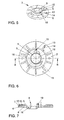
- FIGS. 5 to 7 Another exemplary embodiment of a spring pad is shown in FIGS. 5 to 7, which represents the spring support 3 on the wheel side lying at the bottom in FIG.
- the Spring pad 3 again includes a base element 6 from a Elastomer material for support against a spring plate. Furthermore, the Spring pad 3 is a metallic intermediate plate 7, which points to the spring 1 Side of the base element 6 is arranged.
- the base element 6 and the intermediate plate 7 are essentially as in the first Embodiment designed, so that only the differences in the following is briefly discussed.
- For similar elements in Figures 1 to 4 and in Figures 5 to 7 use the same reference numerals.
- the base element 6 is formed without claw-like projections 11.
- An expiring Winding section of the spring 1 is by the centering section 9 on the Spring pad in a shape adapted to the outgoing winding section 4 Recess 5 held.
- the Flange section 8 of the base element 6 executed with a smaller wall thickness, so that in the area of the recess 5 on the side facing away from the spring 1 protruding wall area 18 results, which closes the recess 5 on the back.
- the Wall section 18 can, for example, be used for centering purposes Spring plates can be used.
- a support projection 19 is located on a radial outer wall of the centering section 9 formed, which is adjacent to the deepest point of the recess 5.
- This support projection 19th serves the radial and axial support of a winding section of the spring 1.
- the spring pad 20 of the third embodiment comprises a base element 21 made of an elastomer material for support against a spring plate, not shown, and an intermediate plate 22, which is arranged on the spring side of the base element 21.
- the intermediate plate 22 is a sacrificial anode for the spring is also preferred here.
- the base element 21 is essentially formed by an annular flange 23 constant wall thickness formed in the middle of a projecting on the spring side Centering section in the form of a collar 24 with a through opening 25.
- a radial projection 26 is provided below centered on an outgoing turn portion of a spring to the spring base 20 and can be axially secured to it.
- the annular flange 23 has on its spring side projections 27 which are elongated Ribs are aligned in the radial direction and through openings 28 of the intermediate plate 22 extend through to project beyond their contact surface 29 for turns of the spring.
- the projections 27 and openings 28 can be as in the two previously described Embodiments are dimensioned, the ring width of the contact surface 29 in Depends on the springs used.
- the spring pad 20 shown in the third embodiment is particularly suitable for springs with a flat end, where for example, the outgoing turn is applied to a previous turn and that If necessary, the end is additionally ground flat.
Landscapes
- Engineering & Computer Science (AREA)
- General Engineering & Computer Science (AREA)
- Mechanical Engineering (AREA)
- Springs (AREA)
- Pens And Brushes (AREA)
- Polishing Bodies And Polishing Tools (AREA)
- Lead Frames For Integrated Circuits (AREA)
- Vehicle Step Arrangements And Article Storage (AREA)
- Braking Arrangements (AREA)
Applications Claiming Priority (2)
| Application Number | Priority Date | Filing Date | Title |
|---|---|---|---|
| DE10009136A DE10009136A1 (de) | 2000-02-26 | 2000-02-26 | Federunterlage |
| DE10009136 | 2000-02-26 |
Publications (3)
| Publication Number | Publication Date |
|---|---|
| EP1128085A2 true EP1128085A2 (fr) | 2001-08-29 |
| EP1128085A3 EP1128085A3 (fr) | 2003-06-25 |
| EP1128085B1 EP1128085B1 (fr) | 2004-09-22 |
Family
ID=7632552
Family Applications (1)
| Application Number | Title | Priority Date | Filing Date |
|---|---|---|---|
| EP01102132A Expired - Lifetime EP1128085B1 (fr) | 2000-02-26 | 2001-02-01 | Support de base de ressort |
Country Status (3)
| Country | Link |
|---|---|
| EP (1) | EP1128085B1 (fr) |
| AT (1) | ATE277303T1 (fr) |
| DE (2) | DE10009136A1 (fr) |
Cited By (4)
| Publication number | Priority date | Publication date | Assignee | Title |
|---|---|---|---|---|
| FR3002996A1 (fr) * | 2013-03-11 | 2014-09-12 | Peugeot Citroen Automobiles Sa | Coupelle et son element de maintien sur un ressort helicoidal |
| WO2017185157A1 (fr) * | 2016-04-25 | 2017-11-02 | S3 Enterprises Inc. | Ressort d'extension à anode sacrificielle |
| WO2021200483A1 (fr) * | 2020-03-31 | 2021-10-07 | 日本発條株式会社 | Dispositif de ressort hélicoïdal |
| EP3766711B1 (fr) * | 2019-07-17 | 2024-08-21 | Ktm Ag | Dispositif de réglage à actionnement pneumatique destiné à l'application d'un dispositif ressort à un dispositif amortisseur de ressort comportant un corps tubulaire |
Families Citing this family (8)
| Publication number | Priority date | Publication date | Assignee | Title |
|---|---|---|---|---|
| DE10249711B4 (de) * | 2002-10-25 | 2007-03-29 | Daimlerchrysler Ag | Kopflager einer Kraftfahrzeugfeder |
| DE102004024033A1 (de) * | 2004-05-11 | 2005-12-01 | Heinrich Reutter | Verfahren zum Justieren der Vorspannung einer Druckwendelfeder |
| DE102005028761A1 (de) * | 2005-06-22 | 2007-01-04 | Zf Friedrichshafen Ag | Federteller für einen Schwingungsdämpfer |
| DE102008062902B4 (de) * | 2008-12-23 | 2022-01-27 | Volkswagen Ag | Schwingungsdämpfer und Schutzkappe zur Befestigung an einem Behälterrohr eines Schwingsdämpfers |
| DE102013009637B4 (de) | 2013-06-06 | 2020-06-18 | Volkswagen Aktiengesellschaft | Federunterlage für eine Schraubenfeder |
| DE102016200142B4 (de) | 2016-01-08 | 2018-04-05 | Ford Global Technologies, Llc | Verbesserte Federunterlage für eine, eine Schraubenfeder aufweisende Fahrzeugradaufhängung |
| DE102017215131A1 (de) | 2017-08-30 | 2019-02-28 | Thyssenkrupp Ag | Federteller |
| CN112283274B (zh) * | 2020-10-24 | 2022-06-21 | 上海耘奇汽车部件有限公司 | 一种减震器弹簧垫及其加工工艺 |
Citations (3)
| Publication number | Priority date | Publication date | Assignee | Title |
|---|---|---|---|---|
| DE19632184A1 (de) | 1996-08-09 | 1998-02-12 | Mannesmann Sachs Ag | Federbein mit elastischer Auflage zwischen Schraubenfeder und Federteller |
| DE4211176C2 (de) | 1992-04-03 | 1998-07-23 | Porsche Ag | Lagerung für ein Federbein eines Kraftfahrzeuges |
| EP0924445A2 (fr) | 1997-12-19 | 1999-06-23 | Trelleborg GmbH | Support de ressort |
Family Cites Families (4)
| Publication number | Priority date | Publication date | Assignee | Title |
|---|---|---|---|---|
| GB527468A (en) * | 1939-04-13 | 1940-10-09 | Morris Motors Ltd | Improvements relating to spring mountings for motor vehicles |
| DE1680532U (de) * | 1953-02-18 | 1954-07-29 | William Dipl Ing Gerb | Federschwingungsdaempfer. |
| DE4007488A1 (de) * | 1990-03-09 | 1991-09-12 | Fichtel & Sachs Ag | Federbein fuer fahrzeuge |
| FR2770271B1 (fr) * | 1997-10-27 | 2002-01-04 | Renault | Tampon de filtration de vibrations pour une suspension de vehicule automobile |
-
2000
- 2000-02-26 DE DE10009136A patent/DE10009136A1/de not_active Withdrawn
-
2001
- 2001-02-01 DE DE50103697T patent/DE50103697D1/de not_active Expired - Lifetime
- 2001-02-01 EP EP01102132A patent/EP1128085B1/fr not_active Expired - Lifetime
- 2001-02-01 AT AT01102132T patent/ATE277303T1/de not_active IP Right Cessation
Patent Citations (3)
| Publication number | Priority date | Publication date | Assignee | Title |
|---|---|---|---|---|
| DE4211176C2 (de) | 1992-04-03 | 1998-07-23 | Porsche Ag | Lagerung für ein Federbein eines Kraftfahrzeuges |
| DE19632184A1 (de) | 1996-08-09 | 1998-02-12 | Mannesmann Sachs Ag | Federbein mit elastischer Auflage zwischen Schraubenfeder und Federteller |
| EP0924445A2 (fr) | 1997-12-19 | 1999-06-23 | Trelleborg GmbH | Support de ressort |
Cited By (7)
| Publication number | Priority date | Publication date | Assignee | Title |
|---|---|---|---|---|
| FR3002996A1 (fr) * | 2013-03-11 | 2014-09-12 | Peugeot Citroen Automobiles Sa | Coupelle et son element de maintien sur un ressort helicoidal |
| WO2014140450A1 (fr) * | 2013-03-11 | 2014-09-18 | Peugeot Citroen Automobiles Sa | Coupelle et son element de maintien sur un ressort helicoïdal |
| WO2017185157A1 (fr) * | 2016-04-25 | 2017-11-02 | S3 Enterprises Inc. | Ressort d'extension à anode sacrificielle |
| EP3766711B1 (fr) * | 2019-07-17 | 2024-08-21 | Ktm Ag | Dispositif de réglage à actionnement pneumatique destiné à l'application d'un dispositif ressort à un dispositif amortisseur de ressort comportant un corps tubulaire |
| WO2021200483A1 (fr) * | 2020-03-31 | 2021-10-07 | 日本発條株式会社 | Dispositif de ressort hélicoïdal |
| JP2021162096A (ja) * | 2020-03-31 | 2021-10-11 | 日本発條株式会社 | コイルばね装置 |
| US12253134B2 (en) | 2020-03-31 | 2025-03-18 | Nhk Spring Co., Ltd. | Coil spring device |
Also Published As
| Publication number | Publication date |
|---|---|
| DE10009136A1 (de) | 2001-08-30 |
| ATE277303T1 (de) | 2004-10-15 |
| EP1128085B1 (fr) | 2004-09-22 |
| DE50103697D1 (de) | 2004-10-28 |
| EP1128085A3 (fr) | 2003-06-25 |
Similar Documents
| Publication | Publication Date | Title |
|---|---|---|
| DE3919775C2 (de) | Abstützlager | |
| EP1233205B1 (fr) | Disposition de ressort | |
| EP0697298B1 (fr) | Palier supportant des charges axiales et radiales pour éléments de suspension de véhicules à moteur | |
| EP1995088B1 (fr) | Elément de palier d'insertion, élément de palier d'insertion élastique et dispositif de support de jambe de suspension à ressort | |
| EP1165331B1 (fr) | Dispositif comportant un ressort a boudins et un palier support pour jambes de force a ressort | |
| EP1128085B1 (fr) | Support de base de ressort | |
| EP0493731B1 (fr) | Flexibloc pour articulation | |
| EP2414180A1 (fr) | Articulation en élastomère | |
| DE102015216736B4 (de) | Federisolator für eine Fahrzeugradaufhängung | |
| EP0520187B1 (fr) | Palier de rotation et translation reprenant des efforts axiaux et ratiaux pour éléments de suspension de véhicules à moteur | |
| DE10032222A1 (de) | Schwenklagerbuchse | |
| DE102018102758A1 (de) | Feder für ein Rückschlagventil, Rückschlagventil mit einer derartigen Feder, regelbarer Schwingungsdämpfer mit einem solchen Rückschlagventil sowie Kraftfahrzeug mit einem derartigen regelbaren Schwingungsdämpfer | |
| EP1817507B1 (fr) | Contour de serrage a base creuse destine a des amortisseurs pneumatiques a soufflet tubulaire | |
| DE2345553B2 (de) | Druckfederanordnung bei einer Fahrzeugfederung | |
| EP1474615B1 (fr) | Articulation elastomere | |
| EP1259743B1 (fr) | Ensemble suspension pneumatique | |
| WO2010085932A1 (fr) | Palier moléculaire, destiné notamment à des véhicules à moteur | |
| DE102022113154B4 (de) | Elastomerlager mit Schutzkappe | |
| EP0548581A1 (fr) | Ressort pneumatique à coussin d'air élastomérique sans talon | |
| EP1923301B1 (fr) | Amortisseur d'oscillations doté d'une butée | |
| EP0748949B1 (fr) | Support radial | |
| DE10258987A1 (de) | Gelenklager | |
| DE20021481U1 (de) | Federwegbegrenzungselement | |
| EP1136346A2 (fr) | Elément de connection pour une liaison élastique entre deux composants de construction | |
| DE19809161B4 (de) | Vorrichtung zur Schwingungsdämpfung an einer Schraubendruckfeder |
Legal Events
| Date | Code | Title | Description |
|---|---|---|---|
| PUAI | Public reference made under article 153(3) epc to a published international application that has entered the european phase |
Free format text: ORIGINAL CODE: 0009012 |
|
| AK | Designated contracting states |
Kind code of ref document: A2 Designated state(s): AT BE CH CY DE DK ES FI FR GB GR IE IT LI LU MC NL PT SE TR |
|
| AX | Request for extension of the european patent |
Free format text: AL;LT;LV;MK;RO;SI |
|
| PUAL | Search report despatched |
Free format text: ORIGINAL CODE: 0009013 |
|
| AK | Designated contracting states |
Designated state(s): AT BE CH CY DE DK ES FI FR GB GR IE IT LI LU MC NL PT SE TR |
|
| AX | Request for extension of the european patent |
Extension state: AL LT LV MK RO SI |
|
| GRAP | Despatch of communication of intention to grant a patent |
Free format text: ORIGINAL CODE: EPIDOSNIGR1 |
|
| 17P | Request for examination filed |
Effective date: 20031229 |
|
| AKX | Designation fees paid |
Designated state(s): AT BE CH CY DE DK ES FI FR GB GR IE IT LI LU MC NL PT SE TR |
|
| GRAS | Grant fee paid |
Free format text: ORIGINAL CODE: EPIDOSNIGR3 |
|
| GRAA | (expected) grant |
Free format text: ORIGINAL CODE: 0009210 |
|
| AK | Designated contracting states |
Kind code of ref document: B1 Designated state(s): AT BE CH CY DE DK ES FI FR GB GR IE IT LI LU MC NL PT SE TR |
|
| PG25 | Lapsed in a contracting state [announced via postgrant information from national office to epo] |
Ref country code: IT Free format text: LAPSE BECAUSE OF FAILURE TO SUBMIT A TRANSLATION OF THE DESCRIPTION OR TO PAY THE FEE WITHIN THE PRESCRIBED TIME-LIMIT;WARNING: LAPSES OF ITALIAN PATENTS WITH EFFECTIVE DATE BEFORE 2007 MAY HAVE OCCURRED AT ANY TIME BEFORE 2007. THE CORRECT EFFECTIVE DATE MAY BE DIFFERENT FROM THE ONE RECORDED. Effective date: 20040922 Ref country code: TR Free format text: LAPSE BECAUSE OF FAILURE TO SUBMIT A TRANSLATION OF THE DESCRIPTION OR TO PAY THE FEE WITHIN THE PRESCRIBED TIME-LIMIT Effective date: 20040922 Ref country code: NL Free format text: LAPSE BECAUSE OF FAILURE TO SUBMIT A TRANSLATION OF THE DESCRIPTION OR TO PAY THE FEE WITHIN THE PRESCRIBED TIME-LIMIT Effective date: 20040922 Ref country code: FI Free format text: LAPSE BECAUSE OF FAILURE TO SUBMIT A TRANSLATION OF THE DESCRIPTION OR TO PAY THE FEE WITHIN THE PRESCRIBED TIME-LIMIT Effective date: 20040922 Ref country code: GB Free format text: LAPSE BECAUSE OF FAILURE TO SUBMIT A TRANSLATION OF THE DESCRIPTION OR TO PAY THE FEE WITHIN THE PRESCRIBED TIME-LIMIT Effective date: 20040922 Ref country code: IE Free format text: LAPSE BECAUSE OF FAILURE TO SUBMIT A TRANSLATION OF THE DESCRIPTION OR TO PAY THE FEE WITHIN THE PRESCRIBED TIME-LIMIT Effective date: 20040922 |
|
| REG | Reference to a national code |
Ref country code: GB Ref legal event code: FG4D Free format text: NOT ENGLISH |
|
| REG | Reference to a national code |
Ref country code: CH Ref legal event code: EP |
|
| REG | Reference to a national code |
Ref country code: IE Ref legal event code: FG4D Free format text: GERMAN |
|
| REF | Corresponds to: |
Ref document number: 50103697 Country of ref document: DE Date of ref document: 20041028 Kind code of ref document: P |
|
| PG25 | Lapsed in a contracting state [announced via postgrant information from national office to epo] |
Ref country code: SE Free format text: LAPSE BECAUSE OF FAILURE TO SUBMIT A TRANSLATION OF THE DESCRIPTION OR TO PAY THE FEE WITHIN THE PRESCRIBED TIME-LIMIT Effective date: 20041222 Ref country code: GR Free format text: LAPSE BECAUSE OF FAILURE TO SUBMIT A TRANSLATION OF THE DESCRIPTION OR TO PAY THE FEE WITHIN THE PRESCRIBED TIME-LIMIT Effective date: 20041222 Ref country code: DK Free format text: LAPSE BECAUSE OF FAILURE TO SUBMIT A TRANSLATION OF THE DESCRIPTION OR TO PAY THE FEE WITHIN THE PRESCRIBED TIME-LIMIT Effective date: 20041222 |
|
| PG25 | Lapsed in a contracting state [announced via postgrant information from national office to epo] |
Ref country code: ES Free format text: LAPSE BECAUSE OF FAILURE TO SUBMIT A TRANSLATION OF THE DESCRIPTION OR TO PAY THE FEE WITHIN THE PRESCRIBED TIME-LIMIT Effective date: 20050102 |
|
| PG25 | Lapsed in a contracting state [announced via postgrant information from national office to epo] |
Ref country code: LU Free format text: LAPSE BECAUSE OF NON-PAYMENT OF DUE FEES Effective date: 20050201 Ref country code: CY Free format text: LAPSE BECAUSE OF FAILURE TO SUBMIT A TRANSLATION OF THE DESCRIPTION OR TO PAY THE FEE WITHIN THE PRESCRIBED TIME-LIMIT Effective date: 20050201 Ref country code: AT Free format text: LAPSE BECAUSE OF NON-PAYMENT OF DUE FEES Effective date: 20050201 |
|
| PG25 | Lapsed in a contracting state [announced via postgrant information from national office to epo] |
Ref country code: MC Free format text: LAPSE BECAUSE OF NON-PAYMENT OF DUE FEES Effective date: 20050228 Ref country code: LI Free format text: LAPSE BECAUSE OF NON-PAYMENT OF DUE FEES Effective date: 20050228 Ref country code: CH Free format text: LAPSE BECAUSE OF NON-PAYMENT OF DUE FEES Effective date: 20050228 Ref country code: BE Free format text: LAPSE BECAUSE OF NON-PAYMENT OF DUE FEES Effective date: 20050228 |
|
| NLV1 | Nl: lapsed or annulled due to failure to fulfill the requirements of art. 29p and 29m of the patents act | ||
| GBV | Gb: ep patent (uk) treated as always having been void in accordance with gb section 77(7)/1977 [no translation filed] |
Effective date: 20040922 |
|
| REG | Reference to a national code |
Ref country code: IE Ref legal event code: FD4D |
|
| ET | Fr: translation filed | ||
| PLBE | No opposition filed within time limit |
Free format text: ORIGINAL CODE: 0009261 |
|
| STAA | Information on the status of an ep patent application or granted ep patent |
Free format text: STATUS: NO OPPOSITION FILED WITHIN TIME LIMIT |
|
| BERE | Be: lapsed |
Owner name: VOLKSWAGEN A.G. Effective date: 20050228 |
|
| 26N | No opposition filed |
Effective date: 20050623 |
|
| REG | Reference to a national code |
Ref country code: CH Ref legal event code: PL |
|
| BERE | Be: lapsed |
Owner name: *VOLKSWAGEN A.G. Effective date: 20050228 |
|
| PG25 | Lapsed in a contracting state [announced via postgrant information from national office to epo] |
Ref country code: PT Free format text: LAPSE BECAUSE OF NON-PAYMENT OF DUE FEES Effective date: 20050222 |
|
| REG | Reference to a national code |
Ref country code: FR Ref legal event code: PLFP Year of fee payment: 16 |
|
| REG | Reference to a national code |
Ref country code: FR Ref legal event code: PLFP Year of fee payment: 17 |
|
| PGFP | Annual fee paid to national office [announced via postgrant information from national office to epo] |
Ref country code: FR Payment date: 20170224 Year of fee payment: 17 Ref country code: DE Payment date: 20170228 Year of fee payment: 17 |
|
| REG | Reference to a national code |
Ref country code: DE Ref legal event code: R119 Ref document number: 50103697 Country of ref document: DE |
|
| REG | Reference to a national code |
Ref country code: FR Ref legal event code: ST Effective date: 20181031 |
|
| PG25 | Lapsed in a contracting state [announced via postgrant information from national office to epo] |
Ref country code: DE Free format text: LAPSE BECAUSE OF NON-PAYMENT OF DUE FEES Effective date: 20180901 |
|
| PG25 | Lapsed in a contracting state [announced via postgrant information from national office to epo] |
Ref country code: FR Free format text: LAPSE BECAUSE OF NON-PAYMENT OF DUE FEES Effective date: 20180228 |