EP1817507B1 - Contour de serrage a base creuse destine a des amortisseurs pneumatiques a soufflet tubulaire - Google Patents
Contour de serrage a base creuse destine a des amortisseurs pneumatiques a soufflet tubulaire Download PDFInfo
- Publication number
- EP1817507B1 EP1817507B1 EP05795926A EP05795926A EP1817507B1 EP 1817507 B1 EP1817507 B1 EP 1817507B1 EP 05795926 A EP05795926 A EP 05795926A EP 05795926 A EP05795926 A EP 05795926A EP 1817507 B1 EP1817507 B1 EP 1817507B1
- Authority
- EP
- European Patent Office
- Prior art keywords
- groove
- bellows
- rolling
- clamping ring
- type pneumatic
- Prior art date
- Legal status (The legal status is an assumption and is not a legal conclusion. Google has not performed a legal analysis and makes no representation as to the accuracy of the status listed.)
- Revoked
Links
Images


Classifications
-
- F—MECHANICAL ENGINEERING; LIGHTING; HEATING; WEAPONS; BLASTING
- F16—ENGINEERING ELEMENTS AND UNITS; GENERAL MEASURES FOR PRODUCING AND MAINTAINING EFFECTIVE FUNCTIONING OF MACHINES OR INSTALLATIONS; THERMAL INSULATION IN GENERAL
- F16F—SPRINGS; SHOCK-ABSORBERS; MEANS FOR DAMPING VIBRATION
- F16F9/00—Springs, vibration-dampers, shock-absorbers, or similarly-constructed movement-dampers using a fluid or the equivalent as damping medium
- F16F9/02—Springs, vibration-dampers, shock-absorbers, or similarly-constructed movement-dampers using a fluid or the equivalent as damping medium using gas only or vacuum
- F16F9/04—Springs, vibration-dampers, shock-absorbers, or similarly-constructed movement-dampers using a fluid or the equivalent as damping medium using gas only or vacuum in a chamber with a flexible wall
- F16F9/0454—Springs, vibration-dampers, shock-absorbers, or similarly-constructed movement-dampers using a fluid or the equivalent as damping medium using gas only or vacuum in a chamber with a flexible wall characterised by the assembling method or by the mounting arrangement, e.g. mounting of the membrane
- F16F9/0463—Springs, vibration-dampers, shock-absorbers, or similarly-constructed movement-dampers using a fluid or the equivalent as damping medium using gas only or vacuum in a chamber with a flexible wall characterised by the assembling method or by the mounting arrangement, e.g. mounting of the membrane with separate crimping rings
Definitions
- the invention relates to a rolling bellows air spring and in particular the attachment of a flexible hose at one end of the bellows each positive fit tensile and pressure-tight to be attached connecting part (air spring cover and / or rolling piston).
- the European patent application 0 319 448 A2 deals with the end-side attachment of an air spring bellows on respective connecting parts.
- the local Fig. 4 shows all the essential details:
- the fastening part has a groove.
- This groove has a base surface which can be provided with circumferential grooves (24).
- the flanks of the groove are partly curved, partly at different angles ⁇ and ⁇ conically inclined.
- the clamping takes place by compression of the bellows over the entire height of a clamping ring.
- the DE 41 42 561 A1 not to press the end portion of the bellows over the entire height of the clamping ring but only at an upper and / or lower "bottleneck" in the region of at least one of the flanks of the mounting groove.
- the Fig. 4 shows at the lower groove flank (22) the "bottleneck” (21), while the bellows over the entire Clamping height of the clamping ring is practically not compressed. Because of the rectangular groove cross-section in this in Fig. 4 shown construction, the insertion of the clamping ring to be mounted does not appear readily possible. A lighter mounting option leaves the in Fig. 1 expect variant shown.
- the object of the present invention therefore consists in a reliable attachment of a hose rolling bellows on a connecting part, wherein a longitudinal displacement of elastomeric material against the integrated strength carrier is largely avoided.
- the plastically deformable clamping ring is radially compressed. Due to the conical design of the groove flanks results in a self-adjusting clamping of each located between the groove and clamping ring Schlauchbalbalgg-end. The located between the clamping ring inner surface and the groove bottom portion of the hose rolling end portion is there just barely clamped, ie only minimally compressed to the amount that allows the incompressibility of the bellows wall.
- the inner edges of the clamping ring are slightly rounded or if the inner edges are provided with a chamfer, a severing of the bellows in the clamping point is reliably avoided.
- the "upper" connection part 8 is in each case an air spring cover, while the “lower” connection part 10 is in each case a rolling piston.
- the connecting parts 8, 10 each have a specially shaped groove 12. In each of these grooves 12, an end portion 4a and 4b of a flexible hose 4 is given and clamped in each case by means of a clamping ring 6.
- By plastic deformation of the clamping ring 6 of the hose 4 is in the circumferential in the respective connection part 8 and / or 10, as a "Tiefbettkontur" trained groove 12 is pressed.
- the air spring 2 differs according to Fig. 2 in such a way that here the Schlauchrollbalg 4 has been "carded” for attachment to the rolling piston 10 first.
- the outside of the respective hose rolling-bellows end 4b comes to rest on the contact surface of the groove 12 of the rolling piston 10, while the inside of the hose-rolling-bellows end 4b bears against the inside of the clamping ring 6.
- connection part 8, 10 cover 8 and / or rolling piston 10) located groove 12 shows the Fig. 3 .
- the groove 12 has a frusto-conical cross-section with a rectilinear ground 14 of height H N and rectilinear bevelled side edges 16a, 16b.
- the two side flanks 16a, 16b are inclined relative to the perpendicular L by the angle ⁇ , so that the groove 12 is wider at its opening than at its base 14.
- the depth of the groove 12 is designated by "T”.
- the depth T of the groove 12 is greater than the thickness S of the flexible hose 4.
- the inside of the clamping ring 6 is below the upper edges of the groove flanks 16a, 16b to lie.
- the distance from the deep bed bottom 14 to the clamping ring 6 corresponds approximately to the wall thickness S of the flexible hose 4.
- the clamping ring 6 is provided at its peripheral edges with chamfers (0.5 x 45 °).
- the depth of the groove 12 should be approximately Balgwandher + 1 ⁇ 2 clamping ring width B.
- the reduction of the bellows wall thickness S in the Clamping ring edge can be varied.
- the optimum bellows wall thickness reduction can be between 30% and 75% bellows wall thickness S.
- the clamping according to the invention has two “bottlenecks", namely one between the upper and the lower inner edge of the clamping ring 6 on the one hand and the respective edge 16a and 16b of the groove 12 on the other.
- This results in a punctual compression of the bellows 4 to about 50% of its strength S.
- a two-fold "punctual" compression results only in the sectional image representation.
- a double- circular compression takes place along the inner upper and inner lower edge of the annular clamping ring 6.
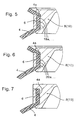
- FIGS. 5 to 7 show special embodiments of the invention Schlauchrollbalg-clamping:
- the groove base 14 has elevations 18a, 18b,..., which are arranged circumferentially on the cylindrical groove surface.
- Fig. 6 are in the groove base 14 circumferential recesses 20a, 20b, ... provided.
- Fig. 7 shows a "one-sided" entrapment of a hose bellows end 4a and 4b.
- D. h . The inventively provided groove flank bevel is formed only on a single groove flank 16 a, while the other groove flank 16 b is rectangular and does not contribute to the clamping of the hose rolling bellows end 4 a and 4 b.
Landscapes
- Engineering & Computer Science (AREA)
- General Engineering & Computer Science (AREA)
- Mechanical Engineering (AREA)
- Fluid-Damping Devices (AREA)
- Clamps And Clips (AREA)
- Rolls And Other Rotary Bodies (AREA)
Claims (5)
- Amortisseur pneumatique (2) à soufflet déroulant, dans lequel au moins une partie d'extrémité (4a, 4b) du soufflet déroulant (4) est fixée en correspondance géométrique, de manière étanche et résistante en traction à une pièce de raccordement (8, 10) au moyen d'un anneau de serrage (6), la pièce de raccordement (8, 10) présentant une rainure de fixation (12) qui a les caractéristiques suivantes :(a) la rainure (12) a une section transversale de forme tronconique,(b) le fond (14) de la rainure (12) est cylindrique et(c) au moins l'un des flancs (16a, 16b) de la rainure (12) est rectiligne et présente un angle d'ouverture de cône (α),(d) la hauteur (HN) de la surface de base (14) de la rainure (12) est comprise dans la plage -15 % à +15 %, c'est-à-dire 0,85 ≤ HN/HS ≤ 1,15, par rapport à la hauteur (HS) de l'anneau de serrage (6),(e) la surface intérieure (6a) de l'anneau de serrage (6) s'étend parallèlement à la surface de base (14) de la rainure (12) ménagée dans la pièce de raccordement (8, 10),(f) à l'état serré, le rayon intérieur de l'anneau de serrage (6) est inférieur ou égal à au moins l'un des rayons des chants supérieurs (17) de la rainure,(g) la distance entre la surface de base (14) de la rainure (12) et le côté intérieur de l'anneau de serrage (6) correspond essentiellement à l'épaisseur S de la paroi du soufflet déroulant (4), diminuée d'une petite valeur pour permettre un léger serrage de la paroi (4a, 4b) du soufflet,(h) l'anneau de serrage (6) forme avec au moins un flanc (16a et/ou 16b) de la rainure un ajustement étroit qui serre la paroi de la partie d'extrémité (4a et/ou 4b) du soufflet.
- Amortisseur pneumatique à soufflet déroulant selon la revendication 1, caractérisé en ce que l'angle (α) formé entre le rayon de l'amortisseur pneumatique et la direction d'au moins l'un des flancs (16a et/ou 16b) de la rainure est compris entre 25° et 35° (25° ≤ α ≤ 35°).
- Amortisseur pneumatique à soufflet déroulant selon les revendications 1 ou 2, caractérisé en ce que le fond (14) de la rainure (12) présente des augmentations concentriques de hauteur (18a, 18b, ...) ou des creux concentriques (20a, 20b, ...).
- Amortisseur pneumatique à soufflet déroulant selon l'une des revendications 1 à 3, caractérisé en ce que les arêtes intérieures (22a, 22b) de l'anneau de serrage (6) sont arrondies et/ou dotées d'un chanfrein.
- Amortisseur pneumatique à soufflet déroulant selon l'une des revendications 1 à 4, caractérisé en ce que le soufflet déroulant (4) est battu avant d'être monté de telle sorte que lorsqu'il est monté, son côté extérieur est en contact avec le fond (14) de la rainure (12) tandis que son côté intérieur (6a) est en contact avec le côté intérieur de l'anneau de serrage (6).
Applications Claiming Priority (2)
| Application Number | Priority Date | Filing Date | Title |
|---|---|---|---|
| DE102004056517A DE102004056517A1 (de) | 2004-11-24 | 2004-11-24 | Tiefbettklemmkontur für Schlauchrollbalg-Luftfedern |
| PCT/EP2005/010789 WO2006056267A1 (fr) | 2004-11-24 | 2005-10-07 | Contour de serrage a base creuse destine a des amortisseurs pneumatiques a soufflet tubulaire |
Publications (2)
| Publication Number | Publication Date |
|---|---|
| EP1817507A1 EP1817507A1 (fr) | 2007-08-15 |
| EP1817507B1 true EP1817507B1 (fr) | 2008-09-03 |
Family
ID=35229669
Family Applications (1)
| Application Number | Title | Priority Date | Filing Date |
|---|---|---|---|
| EP05795926A Revoked EP1817507B1 (fr) | 2004-11-24 | 2005-10-07 | Contour de serrage a base creuse destine a des amortisseurs pneumatiques a soufflet tubulaire |
Country Status (7)
| Country | Link |
|---|---|
| US (1) | US8220785B2 (fr) |
| EP (1) | EP1817507B1 (fr) |
| CN (1) | CN100549452C (fr) |
| AT (1) | ATE407304T1 (fr) |
| BR (1) | BRPI0512034A (fr) |
| DE (2) | DE102004056517A1 (fr) |
| WO (1) | WO2006056267A1 (fr) |
Cited By (1)
| Publication number | Priority date | Publication date | Assignee | Title |
|---|---|---|---|---|
| EP2696095A1 (fr) | 2012-08-07 | 2014-02-12 | Carl Freudenberg KG | Coussin d'air avec raccordements pour la fixation des extrémités d'un soufflet roulant |
Families Citing this family (14)
| Publication number | Priority date | Publication date | Assignee | Title |
|---|---|---|---|---|
| DE10216750A1 (de) * | 2002-04-16 | 2003-10-30 | Contitech Luftfedersyst Gmbh | Schlauchrollbalg-Luftfeder |
| DE102005031477A1 (de) * | 2005-07-04 | 2007-01-11 | Continental Aktiengesellschaft | Luftfeder für Fahrzeuge |
| DE102006037664B4 (de) * | 2006-08-11 | 2022-01-05 | Continental Teves Ag & Co. Ohg | Verfahren zur Klemmung eines Schlauchrollbalgs einer Luftfeder |
| DE102007055077A1 (de) | 2007-11-16 | 2009-05-20 | Continental Aktiengesellschaft | Klemmkontur für ein druckbeaufschlagbares Bauteil und Spannmittel dafür |
| DE102009003822B4 (de) | 2009-04-24 | 2016-09-01 | Continental Teves Ag & Co. Ohg | Druckbeaufschlagbarer Bauteilverbund und Schlauchrollbalg-Luftfeder |
| DE102009052923A1 (de) * | 2009-11-12 | 2011-05-19 | Trw Automotive Gmbh | Kugelgelenk sowie Verfahren zum Befestigen eines Dichtungsbalgs an einem Kugelgelenk |
| US20120098173A1 (en) * | 2010-10-26 | 2012-04-26 | Vibracoustics North America, L.P. | Rebound Control Enhancement For Air Springs |
| US8733743B2 (en) * | 2010-12-23 | 2014-05-27 | Firestone Industrial Products Company, Llc | Gas spring piston, gas spring assembly and method |
| JP5912898B2 (ja) * | 2012-06-18 | 2016-04-27 | 川崎重工業株式会社 | 鉄道車両用台車 |
| JP5939065B2 (ja) * | 2012-07-19 | 2016-06-22 | 住友電気工業株式会社 | 空気ばね |
| US9387865B2 (en) * | 2013-02-18 | 2016-07-12 | Firestone Industrial Products Company, Llc | End member assemblies as well as gas spring assemblies and methods of manufacture including same |
| DE102016100939B4 (de) * | 2016-01-20 | 2023-08-10 | Vibracoustic Cv Air Springs Gmbh | Luftfeder |
| CN107906152A (zh) * | 2017-11-28 | 2018-04-13 | 东风商用车有限公司 | 一种小体积低刚度气囊弹簧 |
| DE112020001936T5 (de) * | 2019-04-15 | 2022-01-13 | ILJIN USA Corporation | Luftfedern und verfahren zur herstellung derselben |
Family Cites Families (11)
| Publication number | Priority date | Publication date | Assignee | Title |
|---|---|---|---|---|
| JPS6044630A (ja) * | 1983-08-23 | 1985-03-09 | Sumitomo Electric Ind Ltd | 空気ばね |
| DE3346108A1 (de) * | 1983-12-21 | 1985-07-04 | Continental Gummi Werke Ag | Luftfederung insbesondere fuer strassenfahrzeuge |
| US4793598A (en) * | 1986-09-24 | 1988-12-27 | The Firestone Tire & Rubber Company | Air spring having internal sealing band and method of installing same |
| DE3643073A1 (de) * | 1986-12-17 | 1988-06-30 | Phoenix Ag | Luftfeder |
| US5005808A (en) * | 1987-12-01 | 1991-04-09 | The Goodyear Tire & Rubber Company | Airspring end member and airspring assembly |
| DE4142561C2 (de) * | 1991-12-21 | 1995-04-27 | Continental Ag | Luftfeder mit einem wulstlosen Luftfederbalg aus elastomerem Werkstoff |
| US5382006A (en) * | 1993-09-29 | 1995-01-17 | The Goodyear Tire & Rubber Company | Airspring piston and airspring assembly |
| DE4423601C2 (de) * | 1994-07-06 | 1997-08-21 | Continental Ag | Luftfederrollbalg aus elastomerem Werkstoff |
| CN2311654Y (zh) * | 1996-12-04 | 1999-03-24 | 铁道部四方车辆研究所 | 弹性支承可调阻尼式空气弹簧 |
| US6036180A (en) * | 1998-02-26 | 2000-03-14 | Bridgestone/Firestone, Inc. | Tear-drop shaped clamp assembly and tapered end cap for an air spring |
| DE502004009679D1 (de) | 2003-04-03 | 2009-08-13 | Freudenberg Carl Kg | Luftfederanordnung |
-
2004
- 2004-11-24 DE DE102004056517A patent/DE102004056517A1/de not_active Withdrawn
-
2005
- 2005-10-07 CN CNB2005800403463A patent/CN100549452C/zh not_active Expired - Fee Related
- 2005-10-07 WO PCT/EP2005/010789 patent/WO2006056267A1/fr not_active Ceased
- 2005-10-07 DE DE502005005289T patent/DE502005005289D1/de not_active Expired - Lifetime
- 2005-10-07 US US11/791,211 patent/US8220785B2/en not_active Expired - Fee Related
- 2005-10-07 AT AT05795926T patent/ATE407304T1/de not_active IP Right Cessation
- 2005-10-07 EP EP05795926A patent/EP1817507B1/fr not_active Revoked
- 2005-10-07 BR BRPI0512034-9A patent/BRPI0512034A/pt not_active IP Right Cessation
Cited By (2)
| Publication number | Priority date | Publication date | Assignee | Title |
|---|---|---|---|---|
| EP2696095A1 (fr) | 2012-08-07 | 2014-02-12 | Carl Freudenberg KG | Coussin d'air avec raccordements pour la fixation des extrémités d'un soufflet roulant |
| WO2014023461A1 (fr) | 2012-08-07 | 2014-02-13 | Carl Freudenberg Kg | Ressort pneumatique muni de raccordements servant à la fixation des extrémités d'un soufflet déroulant |
Also Published As
| Publication number | Publication date |
|---|---|
| DE502005005289D1 (de) | 2008-10-16 |
| US20080290570A1 (en) | 2008-11-27 |
| WO2006056267A1 (fr) | 2006-06-01 |
| BRPI0512034A (pt) | 2008-02-06 |
| CN101065601A (zh) | 2007-10-31 |
| US8220785B2 (en) | 2012-07-17 |
| DE102004056517A1 (de) | 2006-06-01 |
| ATE407304T1 (de) | 2008-09-15 |
| CN100549452C (zh) | 2009-10-14 |
| EP1817507A1 (fr) | 2007-08-15 |
Similar Documents
| Publication | Publication Date | Title |
|---|---|---|
| EP1817507B1 (fr) | Contour de serrage a base creuse destine a des amortisseurs pneumatiques a soufflet tubulaire | |
| DE69112603T2 (de) | Einschnappbaren Stossfänger für Lüftfedern. | |
| DE69602789T2 (de) | Aufhängungssystem | |
| EP0520164A1 (fr) | Raccord à vis | |
| DE112008004188T5 (de) | Grommet | |
| EP1270987A2 (fr) | Support pour un agrégat en forme de manchon | |
| EP0493731B1 (fr) | Flexibloc pour articulation | |
| EP1778988B1 (fr) | Joint spherique | |
| WO1998005520A1 (fr) | Support a balancier et procede permettant de le produire | |
| EP0863334B1 (fr) | Soufflet | |
| EP1128085A2 (fr) | Support de base de ressort | |
| DE4325576C2 (de) | Luftfeder für Fahrzeuge mit einem elastomeren, kernlosen Schlauchrollbalg | |
| EP0548581B1 (fr) | Ressort pneumatique à coussin d'air élastomérique sans talon | |
| WO2000020772A1 (fr) | Ensemble annele premonte destine a envelopper des arbres articules | |
| EP0734888A1 (fr) | Fixation supérieure pour jambe de suspension de véhicule à moteur | |
| DE10338065B4 (de) | Sicherheitsvorrichtung | |
| DE19928599C5 (de) | Elastisches Lager zum Abstützen eines Bauteils | |
| DE10247757B3 (de) | Drehmomentstütze, insbesondere zum Abstützen des Motors an der Karosserie eines Kraftfahrzeugs | |
| EP0939710A1 (fr) | Systeme d'essuie-glace | |
| DE3030878A1 (de) | Kupplungsausruecklager | |
| DE4136598C2 (de) | Gummi-Metall-Federelement | |
| DE3824854A1 (de) | Verbindungselement fuer langgestreckte teile | |
| DE10213064A1 (de) | Elastomere Dichtung | |
| EP1391619B1 (fr) | Joint à rotule | |
| DE3610283A1 (de) | Gelenkverbindung |
Legal Events
| Date | Code | Title | Description |
|---|---|---|---|
| PUAI | Public reference made under article 153(3) epc to a published international application that has entered the european phase |
Free format text: ORIGINAL CODE: 0009012 |
|
| 17P | Request for examination filed |
Effective date: 20070625 |
|
| AK | Designated contracting states |
Kind code of ref document: A1 Designated state(s): AT BE BG CH CY CZ DE DK EE ES FI FR GB GR HU IE IS IT LI LT LU LV MC NL PL PT RO SE SI SK TR |
|
| DAX | Request for extension of the european patent (deleted) | ||
| GRAP | Despatch of communication of intention to grant a patent |
Free format text: ORIGINAL CODE: EPIDOSNIGR1 |
|
| GRAS | Grant fee paid |
Free format text: ORIGINAL CODE: EPIDOSNIGR3 |
|
| GRAA | (expected) grant |
Free format text: ORIGINAL CODE: 0009210 |
|
| RTI1 | Title (correction) |
Free format text: DROP BASE RING CLAMPING CONTOUR FOR ROLLING-BELLOWS-TYPE PNEUMATIC SPRINGS |
|
| AK | Designated contracting states |
Kind code of ref document: B1 Designated state(s): AT BE BG CH CY CZ DE DK EE ES FI FR GB GR HU IE IS IT LI LT LU LV MC NL PL PT RO SE SI SK TR |
|
| REG | Reference to a national code |
Ref country code: GB Ref legal event code: FG4D Free format text: NOT ENGLISH |
|
| REG | Reference to a national code |
Ref country code: CH Ref legal event code: EP |
|
| REG | Reference to a national code |
Ref country code: IE Ref legal event code: FG4D Free format text: LANGUAGE OF EP DOCUMENT: GERMAN |
|
| REF | Corresponds to: |
Ref document number: 502005005289 Country of ref document: DE Date of ref document: 20081016 Kind code of ref document: P |
|
| REG | Reference to a national code |
Ref country code: SE Ref legal event code: TRGR |
|
| PG25 | Lapsed in a contracting state [announced via postgrant information from national office to epo] |
Ref country code: NL Free format text: LAPSE BECAUSE OF FAILURE TO SUBMIT A TRANSLATION OF THE DESCRIPTION OR TO PAY THE FEE WITHIN THE PRESCRIBED TIME-LIMIT Effective date: 20080903 Ref country code: LT Free format text: LAPSE BECAUSE OF FAILURE TO SUBMIT A TRANSLATION OF THE DESCRIPTION OR TO PAY THE FEE WITHIN THE PRESCRIBED TIME-LIMIT Effective date: 20080903 |
|
| PG25 | Lapsed in a contracting state [announced via postgrant information from national office to epo] |
Ref country code: ES Free format text: LAPSE BECAUSE OF FAILURE TO SUBMIT A TRANSLATION OF THE DESCRIPTION OR TO PAY THE FEE WITHIN THE PRESCRIBED TIME-LIMIT Effective date: 20081214 Ref country code: FI Free format text: LAPSE BECAUSE OF FAILURE TO SUBMIT A TRANSLATION OF THE DESCRIPTION OR TO PAY THE FEE WITHIN THE PRESCRIBED TIME-LIMIT Effective date: 20080903 Ref country code: SI Free format text: LAPSE BECAUSE OF FAILURE TO SUBMIT A TRANSLATION OF THE DESCRIPTION OR TO PAY THE FEE WITHIN THE PRESCRIBED TIME-LIMIT Effective date: 20080903 Ref country code: LV Free format text: LAPSE BECAUSE OF FAILURE TO SUBMIT A TRANSLATION OF THE DESCRIPTION OR TO PAY THE FEE WITHIN THE PRESCRIBED TIME-LIMIT Effective date: 20080903 |
|
| NLV1 | Nl: lapsed or annulled due to failure to fulfill the requirements of art. 29p and 29m of the patents act | ||
| REG | Reference to a national code |
Ref country code: IE Ref legal event code: FD4D |
|
| BERE | Be: lapsed |
Owner name: CONTITECH LUFTFEDERSYSTEME G.M.B.H. Effective date: 20081031 |
|
| PG25 | Lapsed in a contracting state [announced via postgrant information from national office to epo] |
Ref country code: BG Free format text: LAPSE BECAUSE OF FAILURE TO SUBMIT A TRANSLATION OF THE DESCRIPTION OR TO PAY THE FEE WITHIN THE PRESCRIBED TIME-LIMIT Effective date: 20081203 Ref country code: IE Free format text: LAPSE BECAUSE OF FAILURE TO SUBMIT A TRANSLATION OF THE DESCRIPTION OR TO PAY THE FEE WITHIN THE PRESCRIBED TIME-LIMIT Effective date: 20080903 |
|
| PG25 | Lapsed in a contracting state [announced via postgrant information from national office to epo] |
Ref country code: SK Free format text: LAPSE BECAUSE OF FAILURE TO SUBMIT A TRANSLATION OF THE DESCRIPTION OR TO PAY THE FEE WITHIN THE PRESCRIBED TIME-LIMIT Effective date: 20080903 Ref country code: RO Free format text: LAPSE BECAUSE OF FAILURE TO SUBMIT A TRANSLATION OF THE DESCRIPTION OR TO PAY THE FEE WITHIN THE PRESCRIBED TIME-LIMIT Effective date: 20080903 Ref country code: PT Free format text: LAPSE BECAUSE OF FAILURE TO SUBMIT A TRANSLATION OF THE DESCRIPTION OR TO PAY THE FEE WITHIN THE PRESCRIBED TIME-LIMIT Effective date: 20090203 Ref country code: CZ Free format text: LAPSE BECAUSE OF FAILURE TO SUBMIT A TRANSLATION OF THE DESCRIPTION OR TO PAY THE FEE WITHIN THE PRESCRIBED TIME-LIMIT Effective date: 20080903 Ref country code: IS Free format text: LAPSE BECAUSE OF FAILURE TO SUBMIT A TRANSLATION OF THE DESCRIPTION OR TO PAY THE FEE WITHIN THE PRESCRIBED TIME-LIMIT Effective date: 20090103 Ref country code: MC Free format text: LAPSE BECAUSE OF NON-PAYMENT OF DUE FEES Effective date: 20081031 |
|
| PLBI | Opposition filed |
Free format text: ORIGINAL CODE: 0009260 |
|
| 26 | Opposition filed |
Opponent name: CARL FREUDENBERG KG Effective date: 20090528 |
|
| PLAX | Notice of opposition and request to file observation + time limit sent |
Free format text: ORIGINAL CODE: EPIDOSNOBS2 |
|
| PG25 | Lapsed in a contracting state [announced via postgrant information from national office to epo] |
Ref country code: EE Free format text: LAPSE BECAUSE OF FAILURE TO SUBMIT A TRANSLATION OF THE DESCRIPTION OR TO PAY THE FEE WITHIN THE PRESCRIBED TIME-LIMIT Effective date: 20080903 Ref country code: DK Free format text: LAPSE BECAUSE OF FAILURE TO SUBMIT A TRANSLATION OF THE DESCRIPTION OR TO PAY THE FEE WITHIN THE PRESCRIBED TIME-LIMIT Effective date: 20080903 |
|
| PG25 | Lapsed in a contracting state [announced via postgrant information from national office to epo] |
Ref country code: IT Free format text: LAPSE BECAUSE OF FAILURE TO SUBMIT A TRANSLATION OF THE DESCRIPTION OR TO PAY THE FEE WITHIN THE PRESCRIBED TIME-LIMIT Effective date: 20080903 |
|
| PG25 | Lapsed in a contracting state [announced via postgrant information from national office to epo] |
Ref country code: BE Free format text: LAPSE BECAUSE OF NON-PAYMENT OF DUE FEES Effective date: 20081031 |
|
| PLBB | Reply of patent proprietor to notice(s) of opposition received |
Free format text: ORIGINAL CODE: EPIDOSNOBS3 |
|
| PG25 | Lapsed in a contracting state [announced via postgrant information from national office to epo] |
Ref country code: AT Free format text: LAPSE BECAUSE OF NON-PAYMENT OF DUE FEES Effective date: 20081007 |
|
| PG25 | Lapsed in a contracting state [announced via postgrant information from national office to epo] |
Ref country code: PL Free format text: LAPSE BECAUSE OF FAILURE TO SUBMIT A TRANSLATION OF THE DESCRIPTION OR TO PAY THE FEE WITHIN THE PRESCRIBED TIME-LIMIT Effective date: 20080903 |
|
| REG | Reference to a national code |
Ref country code: CH Ref legal event code: PL |
|
| PG25 | Lapsed in a contracting state [announced via postgrant information from national office to epo] |
Ref country code: LU Free format text: LAPSE BECAUSE OF NON-PAYMENT OF DUE FEES Effective date: 20081007 Ref country code: CY Free format text: LAPSE BECAUSE OF FAILURE TO SUBMIT A TRANSLATION OF THE DESCRIPTION OR TO PAY THE FEE WITHIN THE PRESCRIBED TIME-LIMIT Effective date: 20080903 |
|
| PG25 | Lapsed in a contracting state [announced via postgrant information from national office to epo] |
Ref country code: CH Free format text: LAPSE BECAUSE OF NON-PAYMENT OF DUE FEES Effective date: 20091031 Ref country code: LI Free format text: LAPSE BECAUSE OF NON-PAYMENT OF DUE FEES Effective date: 20091031 Ref country code: GR Free format text: LAPSE BECAUSE OF FAILURE TO SUBMIT A TRANSLATION OF THE DESCRIPTION OR TO PAY THE FEE WITHIN THE PRESCRIBED TIME-LIMIT Effective date: 20081204 |
|
| PG25 | Lapsed in a contracting state [announced via postgrant information from national office to epo] |
Ref country code: GB Free format text: LAPSE BECAUSE OF NON-PAYMENT OF DUE FEES Effective date: 20091007 |
|
| APBM | Appeal reference recorded |
Free format text: ORIGINAL CODE: EPIDOSNREFNO |
|
| APBP | Date of receipt of notice of appeal recorded |
Free format text: ORIGINAL CODE: EPIDOSNNOA2O |
|
| APAH | Appeal reference modified |
Free format text: ORIGINAL CODE: EPIDOSCREFNO |
|
| APBQ | Date of receipt of statement of grounds of appeal recorded |
Free format text: ORIGINAL CODE: EPIDOSNNOA3O |
|
| PGFP | Annual fee paid to national office [announced via postgrant information from national office to epo] |
Ref country code: TR Payment date: 20120928 Year of fee payment: 8 |
|
| PGFP | Annual fee paid to national office [announced via postgrant information from national office to epo] |
Ref country code: HU Payment date: 20121029 Year of fee payment: 8 Ref country code: DE Payment date: 20121031 Year of fee payment: 8 |
|
| REG | Reference to a national code |
Ref country code: DE Ref legal event code: R064 Ref document number: 502005005289 Country of ref document: DE Ref country code: DE Ref legal event code: R103 Ref document number: 502005005289 Country of ref document: DE |
|
| APBU | Appeal procedure closed |
Free format text: ORIGINAL CODE: EPIDOSNNOA9O |
|
| PLAB | Opposition data, opponent's data or that of the opponent's representative modified |
Free format text: ORIGINAL CODE: 0009299OPPO |
|
| APAN | Information on closure of appeal procedure modified |
Free format text: ORIGINAL CODE: EPIDOSCNOA9O |
|
| R26 | Opposition filed (corrected) |
Opponent name: CARL FREUDENBERG KG Effective date: 20090528 |
|
| APAN | Information on closure of appeal procedure modified |
Free format text: ORIGINAL CODE: EPIDOSCNOA9O |
|
| RDAF | Communication despatched that patent is revoked |
Free format text: ORIGINAL CODE: EPIDOSNREV1 |
|
| RDAG | Patent revoked |
Free format text: ORIGINAL CODE: 0009271 |
|
| STAA | Information on the status of an ep patent application or granted ep patent |
Free format text: STATUS: PATENT REVOKED |
|
| 27W | Patent revoked |
Effective date: 20130716 |
|
| REG | Reference to a national code |
Ref country code: DE Ref legal event code: R107 Ref document number: 502005005289 Country of ref document: DE Effective date: 20140123 |
|
| PGFP | Annual fee paid to national office [announced via postgrant information from national office to epo] |
Ref country code: FR Payment date: 20131022 Year of fee payment: 9 |
|
| REG | Reference to a national code |
Ref country code: AT Ref legal event code: MA03 Ref document number: 407304 Country of ref document: AT Kind code of ref document: T Effective date: 20130716 |
|
| REG | Reference to a national code |
Ref country code: SE Ref legal event code: ECNC |
|
| PGFP | Annual fee paid to national office [announced via postgrant information from national office to epo] |
Ref country code: SE Payment date: 20141021 Year of fee payment: 10 |