EP1128351A2 - Système de contrôle du déplacement d'un véhicule - Google Patents
Système de contrôle du déplacement d'un véhicule Download PDFInfo
- Publication number
- EP1128351A2 EP1128351A2 EP01103666A EP01103666A EP1128351A2 EP 1128351 A2 EP1128351 A2 EP 1128351A2 EP 01103666 A EP01103666 A EP 01103666A EP 01103666 A EP01103666 A EP 01103666A EP 1128351 A2 EP1128351 A2 EP 1128351A2
- Authority
- EP
- European Patent Office
- Prior art keywords
- vehicle
- following distance
- detecting means
- detecting
- appropriate
- Prior art date
- Legal status (The legal status is an assumption and is not a legal conclusion. Google has not performed a legal analysis and makes no representation as to the accuracy of the status listed.)
- Granted
Links
- 238000011156 evaluation Methods 0.000 claims description 56
- 238000000034 method Methods 0.000 claims description 13
- 238000009413 insulation Methods 0.000 claims description 8
- 238000010276 construction Methods 0.000 description 2
- 238000005516 engineering process Methods 0.000 description 2
- 239000012530 fluid Substances 0.000 description 2
- 238000007792 addition Methods 0.000 description 1
- 238000010586 diagram Methods 0.000 description 1
- 230000001678 irradiating effect Effects 0.000 description 1
Images


Classifications
-
- B—PERFORMING OPERATIONS; TRANSPORTING
- B60—VEHICLES IN GENERAL
- B60Q—ARRANGEMENT OF SIGNALLING OR LIGHTING DEVICES, THE MOUNTING OR SUPPORTING THEREOF OR CIRCUITS THEREFOR, FOR VEHICLES IN GENERAL
- B60Q9/00—Arrangement or adaptation of signal devices not provided for in one of main groups B60Q1/00 - B60Q7/00, e.g. haptic signalling
- B60Q9/008—Arrangement or adaptation of signal devices not provided for in one of main groups B60Q1/00 - B60Q7/00, e.g. haptic signalling for anti-collision purposes
-
- B—PERFORMING OPERATIONS; TRANSPORTING
- B60—VEHICLES IN GENERAL
- B60K—ARRANGEMENT OR MOUNTING OF PROPULSION UNITS OR OF TRANSMISSIONS IN VEHICLES; ARRANGEMENT OR MOUNTING OF PLURAL DIVERSE PRIME-MOVERS IN VEHICLES; AUXILIARY DRIVES FOR VEHICLES; INSTRUMENTATION OR DASHBOARDS FOR VEHICLES; ARRANGEMENTS IN CONNECTION WITH COOLING, AIR INTAKE, GAS EXHAUST OR FUEL SUPPLY OF PROPULSION UNITS IN VEHICLES
- B60K31/00—Vehicle fittings, acting on a single sub-unit only, for automatically controlling vehicle speed, i.e. preventing speed from exceeding an arbitrarily established velocity or maintaining speed at a particular velocity, as selected by the vehicle operator
- B60K31/0008—Vehicle fittings, acting on a single sub-unit only, for automatically controlling vehicle speed, i.e. preventing speed from exceeding an arbitrarily established velocity or maintaining speed at a particular velocity, as selected by the vehicle operator including means for detecting potential obstacles in vehicle path
-
- B—PERFORMING OPERATIONS; TRANSPORTING
- B60—VEHICLES IN GENERAL
- B60W—CONJOINT CONTROL OF VEHICLE SUB-UNITS OF DIFFERENT TYPE OR DIFFERENT FUNCTION; CONTROL SYSTEMS SPECIALLY ADAPTED FOR HYBRID VEHICLES; ROAD VEHICLE DRIVE CONTROL SYSTEMS FOR PURPOSES NOT RELATED TO THE CONTROL OF A PARTICULAR SUB-UNIT
- B60W50/00—Details of control systems for road vehicle drive control not related to the control of a particular sub-unit, e.g. process diagnostic or vehicle driver interfaces
- B60W2050/0001—Details of the control system
- B60W2050/0043—Signal treatments, identification of variables or parameters, parameter estimation or state estimation
- B60W2050/0057—Frequency analysis, spectral techniques or transforms
-
- B—PERFORMING OPERATIONS; TRANSPORTING
- B60—VEHICLES IN GENERAL
- B60W—CONJOINT CONTROL OF VEHICLE SUB-UNITS OF DIFFERENT TYPE OR DIFFERENT FUNCTION; CONTROL SYSTEMS SPECIALLY ADAPTED FOR HYBRID VEHICLES; ROAD VEHICLE DRIVE CONTROL SYSTEMS FOR PURPOSES NOT RELATED TO THE CONTROL OF A PARTICULAR SUB-UNIT
- B60W2540/00—Input parameters relating to occupants
- B60W2540/18—Steering angle
-
- B—PERFORMING OPERATIONS; TRANSPORTING
- B60—VEHICLES IN GENERAL
- B60W—CONJOINT CONTROL OF VEHICLE SUB-UNITS OF DIFFERENT TYPE OR DIFFERENT FUNCTION; CONTROL SYSTEMS SPECIALLY ADAPTED FOR HYBRID VEHICLES; ROAD VEHICLE DRIVE CONTROL SYSTEMS FOR PURPOSES NOT RELATED TO THE CONTROL OF A PARTICULAR SUB-UNIT
- B60W2754/00—Output or target parameters relating to objects
- B60W2754/10—Spatial relation or speed relative to objects
- B60W2754/30—Longitudinal distance
-
- B—PERFORMING OPERATIONS; TRANSPORTING
- B60—VEHICLES IN GENERAL
- B60Y—INDEXING SCHEME RELATING TO ASPECTS CROSS-CUTTING VEHICLE TECHNOLOGY
- B60Y2200/00—Type of vehicle
- B60Y2200/10—Road Vehicles
- B60Y2200/14—Trucks; Load vehicles, Busses
-
- B—PERFORMING OPERATIONS; TRANSPORTING
- B60—VEHICLES IN GENERAL
- B60Y—INDEXING SCHEME RELATING TO ASPECTS CROSS-CUTTING VEHICLE TECHNOLOGY
- B60Y2200/00—Type of vehicle
- B60Y2200/10—Road Vehicles
- B60Y2200/14—Trucks; Load vehicles, Busses
- B60Y2200/143—Busses
-
- G—PHYSICS
- G08—SIGNALLING
- G08G—TRAFFIC CONTROL SYSTEMS
- G08G1/00—Traffic control systems for road vehicles
- G08G1/16—Anti-collision systems
- G08G1/166—Anti-collision systems for active traffic, e.g. moving vehicles, pedestrians, bikes
Definitions
- the present invention relates to a vehicular travel control system for performing automatic follow-up control for controlling own vehicle to follow-up a leading vehicle.
- adequacy of the following distance which the driver feel is not determined only by the kind of the leading vehicle.
- the driver of the standard passenger vehicle may feel that the following distance is shorter than that felt when the leading vehicle is the standard passenger vehicle even when the following distance is 5m, for example.
- the leading vehicle is the standard passenger vehicle and the own vehicle as following vehicle is the heavy truck
- the following distance can be felt longer than that felt when the leading vehicle is the heavy truck even when the following distance is 5m, for example.
- the drivability to be felt by the driver of the own vehicle as following vehicle can be differentiate significantly.
- the drivability which the driver may feel at the following distance becomes different significantly. Namely, in day and night, even when the following distance to the leading vehicle is the same, the following distance which the driver may feel, becomes different. That is, in the night where a field of vision is unclear, the following distance that the driver may feel, may be felt shorter.
- an object of the present invention is to provide a vehicular travel control system which can perform automatic follow-up control for maintaining a following distance matching with drivability which a driver may feel.
- a vehicular travel control system comprises:
- a vehicular travel control system comprises:
- a vehicular travel control method for controlling a following distance between a leading vehicle and an own vehicle comprises:
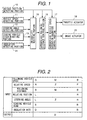
- Fig. 1 shows a construction of one embodiment of a vehicular travel control system according to the present invention.
- a vehicle position detecting portion 10 mounted on an own vehicle has a laser radar, for example, for scanning front side of the own vehicle with irradiating a laser beam at a predetermined pulse interval.
- the scanned laser beam is reflected by a leading vehicle.
- the vehicle position detecting portion 10 detects a following distance, a relative speed and a relative position representative of deviation of traveling directions of the leading vehicle and the own vehicle by receiving the reflected laser beam.
- a vehicle speed detecting portion 11 detects a traveling speed of the own vehicle using a Hall element or the like.
- a steering angle detecting portion 12 detects a steering angle of the own vehicle using a potentiometer or the like.
- a leading vehicle discriminating portion 13 processes an image picked-up by a camera or other image pick-up device for discriminating whether the leading vehicle is a large size vehicle or a standard size vehicle.
- a criterion for discrimination comparison of a projection area by the image pick-up device, size of a number plate, color and so forth can be used.
- an insolation detecting portion 14 detects an insolation as a parameter representative of brightness of driving view field using a photodiode or the like. It should be noted that when a camera is used in the leading vehicle discriminating portion 13, the insolation is detected with reference to a correction value of exposure of the camera.
- the following distance, the relative speed, the relative position, the own vehicle speed, the steering angle, the kind of the leading vehicle and the insolation detected by the vehicle position detecting portion 10, the vehicle speed detecting portion 11, the steering angle detecting portion 12, the leading vehicle discriminating portion 13 and the insolation detecting portion 14 are fed to a drivability calculating portion 15.
- the drivability calculating portion 15 performs arithmetic process for respective of input parameters to derive a drivability indicia matching with the feeling of the driver.
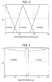
- the drivability calculating portion 15 evaluates the kind of the leading vehicle, the following distance, the relative speed, the relative position and the following vehicle speed as own vehicle speed, the steering angle, the insolation using predetermined evaluation standards to finally output a drivability indicia D depending upon respective results of evaluation.
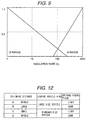
- a following (own) vehicle speed and the following distance are evaluated by three evaluation standards, i.e. S (Small), M (Middle), B (big), respectively.
- Relative position and steering angle are evaluated by three evaluation standards, i.e. L (Left), Z (Zero) and R (Right), respectively.
- the relative speed is evaluated by three evaluation standards, i.e. N (Negative), Z (Zero) and P (Positive).
- the leading vehicle kind is evaluated by two evaluation standards, i.e. S (Small) and B (Big).
- the insolation is evaluated by two evaluation standards, i.e. D (Dark) and B (Bright).
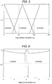
- Fig. 3 shows the evaluation function of the evaluation standards S (small), M (Middle) and B (Big) of the following vehicle speed.
- Fig. 4 shows the evaluation function of the evaluation standards N (Negative), Z (Zero) and P (Positive) of the relative speed.
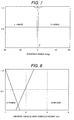
- Fig. 5 shows the evaluation function of the evaluation standard S (small), M (Middle) and B (Big) of the following distance.
- Fig. 6 shows the evaluation function of the evaluation standard L (Left), Z (zero) and R (Right) of the relative position.
- Fig. 7 shows the evaluation function of the evaluation standard L (Left), Z (Zero) and R Right) of steering angle.
- Fig. 8 shows the evaluation function of the evaluation standard S (Small) and B (Big) of the leading vehicle kind.
- Fig. 9 shows the evaluation function of the evaluation standards D (Dark) and B (Bright) of the insolation.
- Fig. 8 shows the case where the vehicular height of the leading vehicle is used as the leading vehicle kind.
- the drivability deriving portion 15 derives the conformity of respective evaluation standards corresponding to respective parameters of the following vehicle speed, the relative speed, the following distance, the relative position, the steering angle, the leading vehicle, the insolation
- the drivability calculating portion 15 finally derives the drivability indicia in the following manner using a control map shown in Fig. 10.
- Fig. 10 shows the control map preliminarily defining correspondence between a combination of the following vehicle speed, the relative speed, the following distance, the relative position, the steering angle, the leading vehicle, the insolation and five evaluation standards, i.e. VL (Very Low), L (Low), M (Middle), H (High) and VH (Very High) of a drivability indicia D and expresses drivability which the driver should feel with respect to a combination of the following vehicle speed, the relative speed, the following distance, the relative position, the steering angle, the leading vehicle, the insolation as a relational rule of respective evaluation standard.
- VL Very Low
- L Low
- M Moddle
- H High
- VH Very High
- a first line of the control map shows a rule "when the following vehicle speed is B (Big), the relative speed is N (Negative), the following distance is S (Small), the relative position is Z (Zero), the steering angle is Z (Zero), the leading vehicle is B (Big) and the insulation is S (Dark), the drivability indicia is VL (Very Low)".
- a third line of the control map shows a rule "when the following vehicle speed is B (Big), the relative speed is N (Negative), the following distance is S (Small), the relative position is Z (Zero), the steering angle is Z (Zero), the leading vehicle is B (Big) and the insulation is B (Bright), the drivability indicia is L (Low)".
- the drivability calculating portion 15 derives satisfaction rate of each rule (each line) of respective control map is derived from a product of conformity derived preliminarily with respect to the following vehicle speed, the relative speed, the following distance, the relative position, the steering angle, the leading vehicle, the insolation described in the rules.
- the drivability indicia D derived by the drivability calculating portion 15 as set forth above is fed to an appropriate following distance calculating portion 16.
- the appropriate following distance calculating portion 16 derives an appropriate following distance between the leading vehicle and the own vehicle using the drivability indicia D received from the drivability calculating portion 15, the relative speed from the vehicle position detecting portion 10 and the following vehicle speed from the vehicle speed detecting portion 11.
- the appropriate following distance calculating portion 16 feeds the derived appropriate following distance L to an appropriate vehicle speed operation magnitude control portion 17.
- the appropriate vehicle speed operation magnitude control 17 receiving the appropriate following distance L performs process shown in Fig. 11.
- a throttle valve actuator 18 is actuated to place a throttle valve at fully closed position to apply an engine brake to the vehicle.
- a brake actuator 19 is actuated for increasing a braking fluid pressure to apply a brake for decelerating the vehicle speed for controlling the following distance G to the appropriate following distance L.
- the throttle actuator 18 is actuated to increase open degree of the throttle valve.
- the brake actuator 19 is actuated to decrease the braking fluid pressure to increase the vehicle speed for controlling the actual following distance G toward the appropriate following distance L.
- the vehicle speed of the following vehicle, the relative speed to the leading vehicle, the following distance, the relative position, the steering angle of the own vehicle, the size of the leading vehicle and the insolation are taken into account for evaluating the drivability to control the following distance depending upon the evaluated drivability. Therefore, by defining an appropriate content of control depending upon the result of evaluation, the following distance can be controlled to attain appropriate drivability.
Landscapes
- Engineering & Computer Science (AREA)
- Mechanical Engineering (AREA)
- Chemical & Material Sciences (AREA)
- Combustion & Propulsion (AREA)
- Transportation (AREA)
- Human Computer Interaction (AREA)
- Control Of Driving Devices And Active Controlling Of Vehicle (AREA)
- Controls For Constant Speed Travelling (AREA)
- Traffic Control Systems (AREA)
- Optical Radar Systems And Details Thereof (AREA)
Applications Claiming Priority (2)
| Application Number | Priority Date | Filing Date | Title |
|---|---|---|---|
| JP2000051032A JP2001243600A (ja) | 2000-02-28 | 2000-02-28 | 車両走行制御装置 |
| JP2000051032 | 2000-02-28 |
Publications (3)
| Publication Number | Publication Date |
|---|---|
| EP1128351A2 true EP1128351A2 (fr) | 2001-08-29 |
| EP1128351A3 EP1128351A3 (fr) | 2001-10-31 |
| EP1128351B1 EP1128351B1 (fr) | 2004-10-06 |
Family
ID=18572739
Family Applications (1)
| Application Number | Title | Priority Date | Filing Date |
|---|---|---|---|
| EP01103666A Expired - Lifetime EP1128351B1 (fr) | 2000-02-28 | 2001-02-23 | Système de contrôle du déplacement d'un véhicule |
Country Status (4)
| Country | Link |
|---|---|
| US (1) | US6347274B2 (fr) |
| EP (1) | EP1128351B1 (fr) |
| JP (1) | JP2001243600A (fr) |
| DE (1) | DE60106106T8 (fr) |
Cited By (3)
| Publication number | Priority date | Publication date | Assignee | Title |
|---|---|---|---|---|
| WO2008086859A1 (fr) * | 2007-01-19 | 2008-07-24 | Daimler Ag | Procédé et système d'assistance au conducteur pour assister un conducteur lors de la conduite d'un véhicule automobile |
| FR2912981A1 (fr) * | 2007-02-22 | 2008-08-29 | Peugeot Citroen Automobiles Sa | Procede de pilotage automatique de vehicule automobile comprenant un systeme acc |
| EP2840004A1 (fr) * | 2013-08-08 | 2015-02-25 | MAN Truck & Bus AG | Système d'assistance du conducteur et procédé de fonctionnement d'un système d'assistance du conducteur pour la régulation longitudinale d'un véhicule |
Families Citing this family (13)
| Publication number | Priority date | Publication date | Assignee | Title |
|---|---|---|---|---|
| US7085739B1 (en) * | 1999-10-20 | 2006-08-01 | Accenture Llp | Method and system for facilitating, coordinating and managing a competitive marketplace |
| JP3838048B2 (ja) * | 2001-04-16 | 2006-10-25 | 日産自動車株式会社 | 車両用走行制御装置 |
| US8718919B2 (en) * | 2002-04-23 | 2014-05-06 | Robert Bosch Gmbh | Method and apparatus for lane recognition for a vehicle |
| DE10345802A1 (de) * | 2003-09-30 | 2005-04-14 | Robert Bosch Gmbh | Verfahren und Vorrichtung zur Fahrspurerkennung für ein Fahrzeug |
| DE10311192A1 (de) * | 2003-03-12 | 2004-09-23 | Robert Bosch Gmbh | Vorrichtung und Verfahren zur Geschwindigkeitsregelung eines Kraftfahrzeugs |
| JP2007283837A (ja) * | 2006-04-13 | 2007-11-01 | Toyota Motor Corp | 車両用運転支援装置 |
| JP4770572B2 (ja) * | 2006-05-09 | 2011-09-14 | トヨタ自動車株式会社 | 通信装置及び移動体制御システム |
| JP5141849B2 (ja) * | 2010-04-07 | 2013-02-13 | トヨタ自動車株式会社 | 車両走行支援装置 |
| US8493196B2 (en) | 2010-11-15 | 2013-07-23 | Bendix Commercial Vehicle Systems Llc | ACB following distance alert and warning adjustment as a function of forward vehicle size and host vehicle mass |
| WO2014006770A1 (fr) * | 2012-07-06 | 2014-01-09 | 本田技研工業株式会社 | Appareil de commande de déplacement de véhicule |
| JP2016030548A (ja) * | 2014-07-30 | 2016-03-07 | アイシン・エィ・ダブリュ株式会社 | 車両運転支援装置、車両運転支援方法及びプログラム |
| JP7521504B2 (ja) * | 2021-08-27 | 2024-07-24 | トヨタ自動車株式会社 | 運転支援装置、車両、走行制御方法及びプログラム |
| DE102024120535A1 (de) * | 2024-07-19 | 2026-01-22 | Bayerische Motoren Werke Aktiengesellschaft | Verfahren zur Spurwechselassistenz, Fahrerassistenzsystem für ein Kraftfahrzeug und Kraftfahrzeug |
Family Cites Families (7)
| Publication number | Priority date | Publication date | Assignee | Title |
|---|---|---|---|---|
| JP2654971B2 (ja) | 1988-07-30 | 1997-09-17 | マツダ株式会社 | 車両用走行制御装置 |
| JP3233739B2 (ja) * | 1993-06-30 | 2001-11-26 | マツダ株式会社 | 自動車の走行制御装置 |
| JP3212218B2 (ja) * | 1994-05-26 | 2001-09-25 | 三菱電機株式会社 | 車両用障害物検出装置 |
| WO1998032030A1 (fr) * | 1997-01-21 | 1998-07-23 | Automotive Systems Laboratory, Inc. | Ysteme predictif de detection de collision |
| JP3690185B2 (ja) * | 1999-05-25 | 2005-08-31 | 日産自動車株式会社 | 先行車追従制御装置 |
| JP3681052B2 (ja) * | 2000-01-11 | 2005-08-10 | 三菱電機株式会社 | 追従走行制御装置 |
| US6269306B1 (en) * | 2000-06-13 | 2001-07-31 | Ford Global Tech. | System and method for estimating sensor errors |
-
2000
- 2000-02-28 JP JP2000051032A patent/JP2001243600A/ja active Pending
-
2001
- 2001-02-23 EP EP01103666A patent/EP1128351B1/fr not_active Expired - Lifetime
- 2001-02-23 DE DE60106106T patent/DE60106106T8/de active Active
- 2001-02-27 US US09/793,428 patent/US6347274B2/en not_active Expired - Lifetime
Cited By (3)
| Publication number | Priority date | Publication date | Assignee | Title |
|---|---|---|---|---|
| WO2008086859A1 (fr) * | 2007-01-19 | 2008-07-24 | Daimler Ag | Procédé et système d'assistance au conducteur pour assister un conducteur lors de la conduite d'un véhicule automobile |
| FR2912981A1 (fr) * | 2007-02-22 | 2008-08-29 | Peugeot Citroen Automobiles Sa | Procede de pilotage automatique de vehicule automobile comprenant un systeme acc |
| EP2840004A1 (fr) * | 2013-08-08 | 2015-02-25 | MAN Truck & Bus AG | Système d'assistance du conducteur et procédé de fonctionnement d'un système d'assistance du conducteur pour la régulation longitudinale d'un véhicule |
Also Published As
| Publication number | Publication date |
|---|---|
| DE60106106T2 (de) | 2006-03-09 |
| EP1128351A3 (fr) | 2001-10-31 |
| EP1128351B1 (fr) | 2004-10-06 |
| DE60106106T8 (de) | 2006-06-08 |
| US6347274B2 (en) | 2002-02-12 |
| DE60106106D1 (de) | 2004-11-11 |
| JP2001243600A (ja) | 2001-09-07 |
| US20010018631A1 (en) | 2001-08-30 |
Similar Documents
| Publication | Publication Date | Title |
|---|---|---|
| EP1128351B1 (fr) | Système de contrôle du déplacement d'un véhicule | |
| US8214124B2 (en) | Cruise control system and method | |
| US7236870B2 (en) | Lane keep control apparatus and method for automotive vehicle | |
| US6233516B1 (en) | Apparatus and method for controlling inter-vehicle distance to another vehicle traveling ahead of automotive vehicle equipped with the apparatus and method | |
| US6332108B1 (en) | Vehicular run controlling apparatus and method for automotive vehicle | |
| EP1078803B1 (fr) | Vehicule, dispositif et procede de commande du roulage de ce dernier | |
| US20020099491A1 (en) | Adaptive cruise control system and method for automotive vehicle with inter-vehicle distance control function | |
| DE102004059131B4 (de) | Steuervorrichtung für ein Fahrzeug | |
| CN107472246A (zh) | 自适应巡航控制系统及其操作方法 | |
| US20170021812A1 (en) | Vehicle acceleration and deceleration control device | |
| US20040236491A1 (en) | Vehicular traveling control apparatus and method | |
| GB2265242A (en) | Method for controlling the distance between moving motor vehicles | |
| JP2019211830A (ja) | 車線変更推定装置および車線変更推定方法と、車両制御装置および車両制御方法 | |
| DE102017105225A1 (de) | Fahrzeugumgebungsüberwachungsvorrichtung | |
| JP3562314B2 (ja) | 車両用制御装置 | |
| GB2265241A (en) | Method for controlling the distance between moving vehicles | |
| US6640181B2 (en) | Vehicle velocity control apparatus and method with preceding vehicle following control function | |
| JPH0817000A (ja) | 車間距離制御装置 | |
| JPH0717298A (ja) | 自動車の走行制御装置 | |
| JPH06262963A (ja) | 運転制御方法および運転制御装置 | |
| JP2004058994A (ja) | 車両走行制御装置 | |
| US11772639B2 (en) | Controlling apparatus and vehicle | |
| JP2503681B2 (ja) | 車両用走行制御装置 | |
| JP2006182258A (ja) | 車両用走行制御装置 | |
| JPH11334554A (ja) | 車両の走行制御装置 |
Legal Events
| Date | Code | Title | Description |
|---|---|---|---|
| PUAI | Public reference made under article 153(3) epc to a published international application that has entered the european phase |
Free format text: ORIGINAL CODE: 0009012 |
|
| AK | Designated contracting states |
Kind code of ref document: A2 Designated state(s): AT BE CH CY DE DK ES FI FR GB GR IE IT LI LU MC NL PT SE TR Kind code of ref document: A2 Designated state(s): DE FR |
|
| AX | Request for extension of the european patent |
Free format text: AL;LT;LV;MK;RO;SI |
|
| PUAL | Search report despatched |
Free format text: ORIGINAL CODE: 0009013 |
|
| AK | Designated contracting states |
Kind code of ref document: A3 Designated state(s): AT BE CH CY DE DK ES FI FR GB GR IE IT LI LU MC NL PT SE TR |
|
| AX | Request for extension of the european patent |
Free format text: AL;LT;LV;MK;RO;SI |
|
| 17P | Request for examination filed |
Effective date: 20020304 |
|
| AKX | Designation fees paid |
Free format text: DE FR |
|
| 17Q | First examination report despatched |
Effective date: 20030811 |
|
| GRAP | Despatch of communication of intention to grant a patent |
Free format text: ORIGINAL CODE: EPIDOSNIGR1 |
|
| GRAS | Grant fee paid |
Free format text: ORIGINAL CODE: EPIDOSNIGR3 |
|
| GRAA | (expected) grant |
Free format text: ORIGINAL CODE: 0009210 |
|
| AK | Designated contracting states |
Kind code of ref document: B1 Designated state(s): DE FR |
|
| REF | Corresponds to: |
Ref document number: 60106106 Country of ref document: DE Date of ref document: 20041111 Kind code of ref document: P |
|
| ET | Fr: translation filed | ||
| PLBE | No opposition filed within time limit |
Free format text: ORIGINAL CODE: 0009261 |
|
| STAA | Information on the status of an ep patent application or granted ep patent |
Free format text: STATUS: NO OPPOSITION FILED WITHIN TIME LIMIT |
|
| 26N | No opposition filed |
Effective date: 20050707 |
|
| REG | Reference to a national code |
Ref country code: FR Ref legal event code: PLFP Year of fee payment: 15 |
|
| PGFP | Annual fee paid to national office [announced via postgrant information from national office to epo] |
Ref country code: DE Payment date: 20150218 Year of fee payment: 15 |
|
| PGFP | Annual fee paid to national office [announced via postgrant information from national office to epo] |
Ref country code: FR Payment date: 20150210 Year of fee payment: 15 |
|
| REG | Reference to a national code |
Ref country code: DE Ref legal event code: R119 Ref document number: 60106106 Country of ref document: DE |
|
| REG | Reference to a national code |
Ref country code: FR Ref legal event code: ST Effective date: 20161028 |
|
| PG25 | Lapsed in a contracting state [announced via postgrant information from national office to epo] |
Ref country code: DE Free format text: LAPSE BECAUSE OF NON-PAYMENT OF DUE FEES Effective date: 20160901 Ref country code: FR Free format text: LAPSE BECAUSE OF NON-PAYMENT OF DUE FEES Effective date: 20160229 |