EP1128462A2 - Wasserdichte und gasdurchlässige Gehäusekonstruktion für Satellitenempfangskonverter - Google Patents
Wasserdichte und gasdurchlässige Gehäusekonstruktion für Satellitenempfangskonverter Download PDFInfo
- Publication number
- EP1128462A2 EP1128462A2 EP01301122A EP01301122A EP1128462A2 EP 1128462 A2 EP1128462 A2 EP 1128462A2 EP 01301122 A EP01301122 A EP 01301122A EP 01301122 A EP01301122 A EP 01301122A EP 1128462 A2 EP1128462 A2 EP 1128462A2
- Authority
- EP
- European Patent Office
- Prior art keywords
- case
- satellite
- broadcast receiving
- receiving converter
- filter
- Prior art date
- Legal status (The legal status is an assumption and is not a legal conclusion. Google has not performed a legal analysis and makes no representation as to the accuracy of the status listed.)
- Granted
Links
Images


Classifications
-
- H—ELECTRICITY
- H01—ELECTRIC ELEMENTS
- H01Q—ANTENNAS, i.e. RADIO AERIALS
- H01Q1/00—Details of, or arrangements associated with, antennas
- H01Q1/42—Housings not intimately mechanically associated with radiating elements, e.g. radome
-
- H—ELECTRICITY
- H01—ELECTRIC ELEMENTS
- H01Q—ANTENNAS, i.e. RADIO AERIALS
- H01Q1/00—Details of, or arrangements associated with, antennas
- H01Q1/02—Arrangements for de-icing; Arrangements for drying-out ; Arrangements for cooling; Arrangements for preventing corrosion
-
- H—ELECTRICITY
- H01—ELECTRIC ELEMENTS
- H01Q—ANTENNAS, i.e. RADIO AERIALS
- H01Q1/00—Details of, or arrangements associated with, antennas
- H01Q1/12—Supports; Mounting means
- H01Q1/22—Supports; Mounting means by structural association with other equipment or articles
- H01Q1/24—Supports; Mounting means by structural association with other equipment or articles with receiving set
- H01Q1/247—Supports; Mounting means by structural association with other equipment or articles with receiving set with frequency mixer, e.g. for direct satellite reception or Doppler radar
Definitions
- the present invention relates to a waterproofing case construction of a satellite-broadcast receiving converter. Description of the Related Art
- the satellite-broadcast receiving converter 21 comprises a body 23 including a cabinet 22, etc. in which a receiving circuit is accommodated, and a coaxial connector 24 mounted to the body 23 to take electric signals out.
- a case 25 comprises a first and second molded case members 26, 27 made of synthetic resin.
- the connector 24 is provided so as to project outwardly through a hole 26a of the first case member 26.
- the case is so constructed that the hole 26a between the connector 24 and the first case 26 is filled with a sealing member 28, the housing 25a made up of the first and second cases 26, 27 is completely sealed, and the air does not flow into the housing 25a from the outside.
- the satellite-broadcast receiving converter having such construction is brought into an inspection device, and the pressure of the air in the inspection device is increased or reduced to check if the housing 25a of the case 25 has leakage of air.
- the accepted satellite-broadcast receiving converter under the inspection is put on the market, set outdoors, and used.
- the conventional satellite-broadcast receiving converter is so constructed as to completely seal the housing 25a of the case 25. Therefore, it has such problems that, particularly in summer, when the outdoor temperature gets higher, the air inside the housing 25a expands and destroys the case 25 or the sealing member 28.
- the case construction of a satellite-broadcast receiving converter comprises a satellite-broadcast receiving converter having a body and a connector, and a case having a housing to accommodate the body; wherein the connector of the satellite-broadcast receiving converter projects outwardly from the case while an entire portion of the body being covered with the case, a portion of the case includes a cavity provided between an inner part and an outer part of the case, a closing part so formed as to close the outer part of the cavity and a hole so made in the closing part as to provide communication between the outside of the case and the cavity, and the inner part of the cavity is closed with a waterproofing and gas-permeable filter.
- the filter is disposed so as not to oppose a face of the closing part.
- the closing part is formed of a thin wall.
- the closing part is formed on the outer surface of the case and the filter is provided on the inner surface of the case.
- the filter is affixed to the case by adhesive.
- the filter is supported by a cabinet making up the body of the satellite-broadcast receiving converter.
- a face of the closing part is disposed perpendicularly to the projecting direction of the connector from the case.
- the closing part is positioned in the vicinity of the connector.
- Fig. 1 is a front view of a case construction of a satellite-broadcast receiving converter according to a first example.
- Fig. 2 is a side view of the case construction of the satellite-broadcast receiving converter of the invention according to the first example.
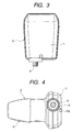
- Fig. 3 is a reverse-side view of the case construction of the satellite-broadcast receiving converter of the invention according to the first example.
- Fig. 4 is an underneath view of the case construction of the satellite-broadcast receiving converter of the invention according to the first example.
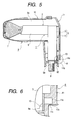
- Fig. 5 is a sectional view of a principal part of the case construction, as viewed sideways, of the satellite-broadcast receiving converter of the invention according to the first example.
- Fig. 6 is an enlarged sectional view of a principal part of A-portion of Fig. 5.
- Fig. 7 is an enlarged sectional view of a principal part of a case construction of a satellite-broadcast receiving converter of the invention according to a second example.
- Fig. 8 is an enlarged sectional view of a principal part of a case construction of a satellite-broadcast receiving converter of the invention according to a third example.
- the satellite-broadcast receiving converter 1 comprises a body 2 and a coaxial connector 8 mounted to the body 2.
- the body 2 comprises a frame 3 made up of a metal plate and a cover 4 made up of a metal plate. It further comprises a box-shaped cabinet 5 accommodating a receiving circuit, a tubular waveguide 6 projecting perpendicularly from the cabinet 5, and a feeder 7 made of an insulating material mounted on a tip of the waveguide 6.
- the coaxial connector 8 is mounted to an end face of the cabinet 5 so as to take electric signals out.
- the case 9 comprises a first and second molded case members 10, 11 made of synthetic resin. Further, with the body 2 being accommodated in the housing 9a, which is formed by combining the first and second case members 10, 11, the connector 8 is provided so as to project outwardly through a hole 9b in the case 9.
- the first case member 10 covers the feeder 7, the waveguide 6 and a front portion of the cabinet 5, and the second case member 11 covers a rear portion of the cabinet 5. Further, the hole 9a between the connector 8 and the case 9 is filled with the sealing member 12, and the housing 9a made up of the first and second case members 10, 11 is sealed.
- a portion of the second case member 11 includes a cavity 11a provided between an inner part or the housing 9a of the case 9 and an outer part or an outer portion of the case 9, and a closing part 11b made up of a thin wall provided so as to close the outer part of the cavity 11a.
- the closing part 11b is provided in the vicinity of the connector 8 and on the outer surface of the second case member 11. Also, a face of the closing part 11b is disposed perpendicularly to the projecting direction of the connector 8 of the case 9.
- the filter 13 is made of waterproofing and gas-permeable material such as, for example, a porous material made of polytetrafluoro-ethylene resin. Adhesive (not shown) is applied on one face of the filter 13, and the filter is affixed to the inner surface of the case 9, or the inner side of the cavity lla, in such a way that it closes the cavity 11a.
- the inner surface of the affixed filter 13 is in contact with the cabinet 5, and the filter 13 is supported while being pressed to the case 9 by the cabinet 5.
- the face with an affixed filter 13 closing the cavity lla and the closing part 11b provided outside are disposed perpendicularly with each other, and the filter 13 is disposed so as not to oppose the face of the closing part 11b.
- a small hole 11c is made in the closing part 11b made up of a thin wall with a pointed jig (not shown).
- the outside of the case 9 and the cavity 11a are in communication through the hole 11c.
- the filter 13 Since the filter 13 is disposed so as not to oppose the face of the closing part 11b, the jig does not contact the filter 13 when a hole is opened with it. Therefore, the filter 13 is prevented from being damaged by the jig.
- the case is constructed such that the housing 9a is completely sealed and the exterior air does not enter the housing 9a.
- a satellite-broadcast receiving converter of which case is without the hole 11c, is brought into an inspection device. Then, by increasing and reducing the pressure to the air in the inspection device, leakage of air in the housing 9a of the case 9 is checked.
- a small hole 11c is made by a jig in the closing part 11b of the accepted satellite-broadcast receiving converter under the inspection so that the air can freely move between the housing 9a and the outside through the filter 13.
- the housing 9a can be water-proofed by means of the filter 13.
- the feeder 7 When setting the satellite-broadcast receiving converter 1 outdoors, the feeder 7 is mounted so as to face the direction of a satellite with the connector 8 underside. Therefore, if the face of the closing part 11b is provided perpendicularly to the projecting direction of the connector 8 of the case 9, the closing part 11b is positioned underside, preventing water such as rain from entering deeper through the hole 11c.
- Fig. 7 shows a second example of the present invention.
- the inner part of the cavity 11b closed by the filter 13 is made small to prevent the entering water in the cavity 11b from reaching the filter 13 directly. Since the rest of the construction is similar to the example described above, like numbers are given to like parts and the description for them is omitted here.
- Fig. 8 shows a third example of the present invention.
- the filter 13 and the closing part 11b are opposed across the cavity 11a.
- like numbers are given to like parts of the first example and the description for them is omitted here.
- the case construction of the satellite-broadcast receiving converter according to the present invention comprises a cavity 11a provided in a portion of the case 9 between the inner part and the outer part of the case 9, a closing part 11b formed so as to close the outer part of the cavity 11a, and a hole 11c made in the closing part 11b to provide communication between the outside of the case 9 and the cavity 11a.
- the inner part of the cavity is closed by the filter 13, which is both waterproofing and gas-permeable and, by way of the hole 11c, the air from the outside can enter and exit from the housing 9a through the filter 13.
- the case 9 and the sealing member 12 are prevented from being destroyed by the expansion and contraction of the air in the housing 9a and, at the same time, water such as rain entering the cavitythrough the hole 11c is prevented from entering the housing 9a by the filter 13.
- leakage of air in the housing 9a of the case 9 can be checked by using a conventional inspection device.
- the filter 13 is disposed so as not to oppose the face of the closing part 11b, a jig does not contact the filter 13 when making a hole 11c in the closing part 11b with it, and the filter 13 can be provided without being damaged by the jig.
- the closing part 11b is formed of a thin wall, it is easy to make a hole 11c in it and the one with good workability can be provided.
- the closing part 11b is formed on the outer surface of the case 9 and the filter 13 is provided on the inner surface, a distance between the filter 13 and the closing part 11b can be made long enough, and the filter 13 without being damaged by the jig can be provided.
- the filter 13 is affixed to the case 9 by adhesive, mounting of the filter 13 is easy and, at the same time, the housing 9a adequately sealed by the filter 13 can be provided.
- the filter 13 is supported by the cabinet 5 making up the body 2 of the satellite-broadcast receiving converter 1, the filter 13 is prevented from coming off so that the filter 13 which does not peel off for a long time can be provided.
- the closing part 11b since the face of the closing part 11b is disposed perpendicularly to the projecting direction of the connector 8 from the case 9, the closing part 11b is positioned underside. Therefore, the construction in which water such as rain via the hole 11c is prevented from entering deeper can be provided.
- the closing part 11b is provided in the vicinity of the connector 8, the closing part 11b is close to the lowest portion of the case 9. Thus, the construction in which water such as rain via the hole 11c is prevented from entering deeper can be provided.
Landscapes
- Engineering & Computer Science (AREA)
- Radar, Positioning & Navigation (AREA)
- Remote Sensing (AREA)
- Structure Of Receivers (AREA)
- Casings For Electric Apparatus (AREA)
- Details Of Aerials (AREA)
- Input Circuits Of Receivers And Coupling Of Receivers And Audio Equipment (AREA)
- Two-Way Televisions, Distribution Of Moving Picture Or The Like (AREA)
Applications Claiming Priority (2)
| Application Number | Priority Date | Filing Date | Title |
|---|---|---|---|
| JP2000054351A JP2001244658A (ja) | 2000-02-25 | 2000-02-25 | 衛星放送受信用コンバータのケース構造 |
| JP2000054351 | 2000-02-25 |
Publications (3)
| Publication Number | Publication Date |
|---|---|
| EP1128462A2 true EP1128462A2 (de) | 2001-08-29 |
| EP1128462A3 EP1128462A3 (de) | 2003-12-10 |
| EP1128462B1 EP1128462B1 (de) | 2005-09-14 |
Family
ID=18575619
Family Applications (1)
| Application Number | Title | Priority Date | Filing Date |
|---|---|---|---|
| EP01301122A Expired - Lifetime EP1128462B1 (de) | 2000-02-25 | 2001-02-08 | Wasserdichte und gasdurchlässige Gehäusekonstruktion für Satellitenempfangskonverter |
Country Status (7)
| Country | Link |
|---|---|
| US (1) | US6400333B2 (de) |
| EP (1) | EP1128462B1 (de) |
| JP (1) | JP2001244658A (de) |
| CN (1) | CN1174666C (de) |
| DE (1) | DE60113318T2 (de) |
| MX (1) | MXPA01002008A (de) |
| TW (1) | TW461235B (de) |
Cited By (3)
| Publication number | Priority date | Publication date | Assignee | Title |
|---|---|---|---|---|
| EP1369953A1 (de) * | 2002-06-06 | 2003-12-10 | Alps Electric Co., Ltd. | Hermetisch abgedichteter Empfangskonverter für Satellitenrundfunk mit einer Entlüftungspore |
| EP1467433A1 (de) * | 2003-04-10 | 2004-10-13 | Alps Electric Co., Ltd. | Konverter für Satellitenrundfunkempfang |
| EP1612902A3 (de) * | 2004-07-02 | 2006-06-07 | Alps Electric Co., Ltd. | Wasserdichtes Gehäuse eines elektronischen Gerätes |
Families Citing this family (3)
| Publication number | Priority date | Publication date | Assignee | Title |
|---|---|---|---|---|
| JP2003101329A (ja) * | 2001-09-20 | 2003-04-04 | Maspro Denkoh Corp | アンテナ装置における信号送受信部の構造 |
| CN100561879C (zh) * | 2005-10-21 | 2009-11-18 | 启碁科技股份有限公司 | 具有遮雨盖的卫星接收器 |
| JP6123903B2 (ja) * | 2013-09-12 | 2017-05-10 | 株式会社村田製作所 | コイル部品 |
Family Cites Families (11)
| Publication number | Priority date | Publication date | Assignee | Title |
|---|---|---|---|---|
| JPS6143707U (ja) * | 1984-08-27 | 1986-03-22 | 日本電気株式会社 | 空気弁 |
| GB8625375D0 (en) * | 1986-10-23 | 1986-11-26 | Gen Electric Co Plc | Protective cover for antenna feed |
| JPH0174613U (de) * | 1987-07-06 | 1989-05-19 | ||
| DE3814276A1 (de) * | 1988-04-27 | 1989-11-09 | Siemens Ag | Aperturstrahler |
| JPH03116091U (de) * | 1990-03-12 | 1991-12-02 | ||
| JP2589308Y2 (ja) * | 1992-01-23 | 1999-01-27 | 株式会社ヨコオ | コンバータ収納用容器 |
| JP3219700B2 (ja) * | 1996-09-18 | 2001-10-15 | 日東電工株式会社 | ベントフィルタ部材 |
| JPH10190491A (ja) | 1996-12-20 | 1998-07-21 | Fujitsu General Ltd | 衛星放送受信用コンバータ |
| US5982336A (en) * | 1997-08-01 | 1999-11-09 | Transystems, Inc. | Structure of super integrated down converter (SIDC) with dual band mechanical and notch filters |
| JPH11186845A (ja) | 1997-12-19 | 1999-07-09 | Fujitsu General Ltd | 一次放射器 |
| US6127986A (en) * | 1998-01-02 | 2000-10-03 | Transystem, Inc. | Integrated down-converter with dipole-antenna implemented with novel mechanical filter structure |
-
2000
- 2000-02-25 JP JP2000054351A patent/JP2001244658A/ja not_active Withdrawn
-
2001
- 2001-01-19 TW TW090101340A patent/TW461235B/zh not_active IP Right Cessation
- 2001-02-08 DE DE60113318T patent/DE60113318T2/de not_active Expired - Fee Related
- 2001-02-08 EP EP01301122A patent/EP1128462B1/de not_active Expired - Lifetime
- 2001-02-21 CN CNB01104120XA patent/CN1174666C/zh not_active Expired - Fee Related
- 2001-02-22 US US09/791,069 patent/US6400333B2/en not_active Expired - Fee Related
- 2001-02-23 MX MXPA01002008A patent/MXPA01002008A/es not_active Application Discontinuation
Cited By (3)
| Publication number | Priority date | Publication date | Assignee | Title |
|---|---|---|---|---|
| EP1369953A1 (de) * | 2002-06-06 | 2003-12-10 | Alps Electric Co., Ltd. | Hermetisch abgedichteter Empfangskonverter für Satellitenrundfunk mit einer Entlüftungspore |
| EP1467433A1 (de) * | 2003-04-10 | 2004-10-13 | Alps Electric Co., Ltd. | Konverter für Satellitenrundfunkempfang |
| EP1612902A3 (de) * | 2004-07-02 | 2006-06-07 | Alps Electric Co., Ltd. | Wasserdichtes Gehäuse eines elektronischen Gerätes |
Also Published As
| Publication number | Publication date |
|---|---|
| TW461235B (en) | 2001-10-21 |
| DE60113318D1 (de) | 2005-10-20 |
| DE60113318T2 (de) | 2006-06-22 |
| MXPA01002008A (es) | 2002-08-20 |
| EP1128462B1 (de) | 2005-09-14 |
| EP1128462A3 (de) | 2003-12-10 |
| JP2001244658A (ja) | 2001-09-07 |
| US6400333B2 (en) | 2002-06-04 |
| CN1312672A (zh) | 2001-09-12 |
| CN1174666C (zh) | 2004-11-03 |
| US20010017601A1 (en) | 2001-08-30 |
Similar Documents
| Publication | Publication Date | Title |
|---|---|---|
| US6778388B1 (en) | Water-resistant electronic enclosure having a heat sink | |
| US5248196A (en) | Insulated wiring harness for domestic refrigerator | |
| US6827232B1 (en) | Resin case providing compatibility between air permeability and water proofing property, and mold for producing such case | |
| CN102045976B (zh) | 电子装置 | |
| JPH08241701A (ja) | バッテリー組立体及びその製造方法 | |
| CN210518454U (zh) | 终端设备的麦克风音腔密封结构以及终端设备 | |
| EP1128462B1 (de) | Wasserdichte und gasdurchlässige Gehäusekonstruktion für Satellitenempfangskonverter | |
| JP2001267000A (ja) | 防水コネクタ | |
| CA2209701A1 (en) | Sealed fuse connector | |
| US7442334B2 (en) | Resin case in which gas-permeability and waterproof quality are compatible, and die for manufacturing such case | |
| EP4167695A1 (de) | Wasserdichter behälter | |
| US20020088636A1 (en) | Portable electronic device | |
| JPH11148880A (ja) | 圧力発信器 | |
| JP2000138469A (ja) | 呼吸孔の防水構造 | |
| JP3927725B2 (ja) | イヤホンジャック防水構造を備えた携帯用無線機並びに携帯用無線機のイヤホンジャック防水方法 | |
| US20050001776A1 (en) | Converter for radio wave reception and antenna apparatus | |
| JPH05167345A (ja) | アンテナ | |
| JPH10224762A (ja) | Catv用増幅器 | |
| KR20010036856A (ko) | 냉장고용 램프 장치 | |
| JP4138698B2 (ja) | 受信コンバータ | |
| JPS62173909A (ja) | 埋込配線器具用パッキン | |
| CN111200681A (zh) | 防水密封结构及终端设备 | |
| JPH11312877A (ja) | 監視カメラの防水ケース | |
| JP2829228B2 (ja) | 同軸導波管変換器 | |
| KR100338996B1 (ko) | 미끄럼방지제어장치의액츄에이터 |
Legal Events
| Date | Code | Title | Description |
|---|---|---|---|
| PUAI | Public reference made under article 153(3) epc to a published international application that has entered the european phase |
Free format text: ORIGINAL CODE: 0009012 |
|
| AK | Designated contracting states |
Kind code of ref document: A2 Designated state(s): AT BE CH CY DE DK ES FI FR GB GR IE IT LI LU MC NL PT SE TR |
|
| AX | Request for extension of the european patent |
Free format text: AL;LT;LV;MK;RO;SI |
|
| PUAL | Search report despatched |
Free format text: ORIGINAL CODE: 0009013 |
|
| AK | Designated contracting states |
Kind code of ref document: A3 Designated state(s): AT BE CH CY DE DK ES FI FR GB GR IE IT LI LU MC NL PT SE TR |
|
| AX | Request for extension of the european patent |
Extension state: AL LT LV MK RO SI |
|
| RIC1 | Information provided on ipc code assigned before grant |
Ipc: 7H 01Q 1/24 B Ipc: 7H 01Q 1/42 A Ipc: 7H 01Q 13/02 B Ipc: 7H 01Q 19/08 B |
|
| 17P | Request for examination filed |
Effective date: 20040105 |
|
| 17Q | First examination report despatched |
Effective date: 20040206 |
|
| AKX | Designation fees paid |
Designated state(s): DE FR GB |
|
| GRAP | Despatch of communication of intention to grant a patent |
Free format text: ORIGINAL CODE: EPIDOSNIGR1 |
|
| GRAS | Grant fee paid |
Free format text: ORIGINAL CODE: EPIDOSNIGR3 |
|
| GRAA | (expected) grant |
Free format text: ORIGINAL CODE: 0009210 |
|
| AK | Designated contracting states |
Kind code of ref document: B1 Designated state(s): DE FR GB |
|
| REG | Reference to a national code |
Ref country code: GB Ref legal event code: FG4D |
|
| REF | Corresponds to: |
Ref document number: 60113318 Country of ref document: DE Date of ref document: 20051020 Kind code of ref document: P |
|
| ET | Fr: translation filed | ||
| PLBE | No opposition filed within time limit |
Free format text: ORIGINAL CODE: 0009261 |
|
| STAA | Information on the status of an ep patent application or granted ep patent |
Free format text: STATUS: NO OPPOSITION FILED WITHIN TIME LIMIT |
|
| 26N | No opposition filed |
Effective date: 20060615 |
|
| PGFP | Annual fee paid to national office [announced via postgrant information from national office to epo] |
Ref country code: GB Payment date: 20081218 Year of fee payment: 9 |
|
| PGFP | Annual fee paid to national office [announced via postgrant information from national office to epo] |
Ref country code: DE Payment date: 20090428 Year of fee payment: 9 |
|
| PGFP | Annual fee paid to national office [announced via postgrant information from national office to epo] |
Ref country code: FR Payment date: 20090114 Year of fee payment: 9 |
|
| GBPC | Gb: european patent ceased through non-payment of renewal fee |
Effective date: 20100208 |
|
| REG | Reference to a national code |
Ref country code: FR Ref legal event code: ST Effective date: 20101029 |
|
| PG25 | Lapsed in a contracting state [announced via postgrant information from national office to epo] |
Ref country code: FR Free format text: LAPSE BECAUSE OF NON-PAYMENT OF DUE FEES Effective date: 20100301 |
|
| PG25 | Lapsed in a contracting state [announced via postgrant information from national office to epo] |
Ref country code: DE Free format text: LAPSE BECAUSE OF NON-PAYMENT OF DUE FEES Effective date: 20100901 |
|
| PG25 | Lapsed in a contracting state [announced via postgrant information from national office to epo] |
Ref country code: GB Free format text: LAPSE BECAUSE OF NON-PAYMENT OF DUE FEES Effective date: 20100208 |